Endress+Hauser Liquiline Control CDC90 Operating Instructions Manual
Automated cleaning and calibration of memosens sensors
Hide thumbs
Also See for Liquiline Control CDC90:
- Operating instructions manual (118 pages) ,
- Brief operating instructions (76 pages) ,
- Operating instructions manual (16 pages)

Related Manuals for Endress+Hauser Liquiline Control CDC90


Summary of Contents for Endress+Hauser Liquiline Control CDC90
- Page 1 Products Solutions Services BA01707C/07/EN/07.21 71514717 2021-01-22 Valid as of version 02.01.00 Operating Instructions Liquiline Control CDC90 Automated cleaning and calibration of Memosens sensors...
-
Page 3: Table Of Contents
Liquiline Control CDC90 Table of contents Table of contents About this document ....4 Commissioning ....57 Symbols . -
Page 4: About This Document
Documentation The following manuals which are available on the complement these Brief Operating Instructions Operating Instructions: • Brief Operating Instructions for Liquiline Control CDC90 • Operating Instructions for Memosens, BA01245C • Software description for Memosens inputs • Calibration of Memosens sensors •... -
Page 5: Basic Safety Instructions
Designated use Liquiline Control CDC90 is a fully automatic measuring, cleaning and calibration system for Memosens sensors. The system is fully equipped with power supply cables and a hose system. - Page 6 Basic safety instructions Liquiline Control CDC90 CAUTION Cleaning not switched off during calibration or maintenance activities Risk of injury due to medium or cleaning agent! ‣ If a cleaning system is connected, switch it off before removing a sensor from the medium.
-
Page 7: Product Safety
Liquiline Control CDC90 Basic safety instructions Product safety 2.5.1 State-of-the-art technology The product is designed to meet state-of-the-art safety requirements, has been tested, and left the factory in a condition in which it is safe to operate. The relevant regulations and international standards have been observed. -
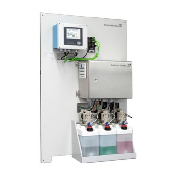
Page 8: Product Description
Product description Liquiline Control CDC90 Product description Product design A complete measuring system comprises the following components: • CDC90 control unit • Pneumatic control unit • Canister pump unit The system is available in different versions. Here is a complete overview comprising all of the system' s modules. - Page 9 Liquiline Control CDC90 Product description 3.1.1 Overview of pneumatic control unit 1st measuring point The pneumatic control unit controls air, liquids and electricity. The supply voltage is applied here, for example. A0044121 2 Pneumatic control unit for one measuring point...
- Page 10 Product description Liquiline Control CDC90 2nd measuring point A0044120 3 Pneumatic control unit for a 2nd measuring point Extension of the output interface terminals for a 2nd measuring point Extension of the pilot valves for a 2nd measuring point...
-
Page 11: Incoming Acceptance And Product
Liquiline Control CDC90 Incoming acceptance and product identification Incoming acceptance and product identification Incoming acceptance 1. Verify that the packaging is undamaged. Notify the supplier of any damage to the packaging. Keep the damaged packaging until the issue has been resolved. -
Page 12: Scope Of Delivery
Incoming acceptance and product identification Liquiline Control CDC90 5. Click on the product image in the popup window. A new window (Device Viewer) opens. All of the information relating to your device is displayed in this window as well as the product documentation. -
Page 13: Installation
Liquiline Control CDC90 Installation Installation Installation conditions The device is intended for wall mounting. Wall mounting as: Panel 5.1.1 Installation site Note the following when erecting the device: 1. Make sure that the wall has sufficient load-bearing capacity and is fully perpendicular. - Page 14 Installation Liquiline Control CDC90 5.2.2 Dimensions of pneumatic control unit 210 (8.27) 380 (15.0) A0031929 5 Dimensions of pneumatic control unit in mm (in) 5.2.3 Dimensions of canister holder 160 (6.3) 150 (5.9) 8.5 (0.33) Ø 470 (18.50) 220 (8.66) A0033139 ...
- Page 15 Liquiline Control CDC90 Installation 65 (2.56) 140 (5.51) 151 (5.94) 190 (7.48) A0032277 7 Dimensions of canister with pump in mm (in) 5.2.4 Dimensions of rinsing block and changeover valve 195 (7.68) 120 (4.72) 108 (4.25) 181 (7.13) 223.5 (8.80) A0032267 ...
-
Page 16: Mounting The System
Installation Liquiline Control CDC90 5.2.5 Dimensions of mounting plate 770 (30.31) 8 (0.31) 8 (0.31) 150 (6.00) 380 (15.00) 20 (0.79) 600 (23.62) 86 (3.39) A0031946 10 Dimensions of mounting plate in mm (in) Mounting the system 5.3.1 Wall mounting... - Page 17 Liquiline Control CDC90 Installation The mounting plate features drill holes for the bracket on the wall. The wall plugs and screws must be provided by the customer. 1. Mount the mounting plate at the securing holes provided for this purpose and using the enclosed distance sleeves.
- Page 18 Installation Liquiline Control CDC90 Rinsing block bracket on assembly A0032669 13 Mounting the rinsing block bracket 1. Fit one half of the rinsing block bracket (1) on the assembly cylinder. 2. Fit the counterpart (3) on the assembly cylinder from the other side.
- Page 19 Liquiline Control CDC90 Installation Connecting the individual hoses in the multihose to the rinsing block valve A0032739 1. Unscrew the head of the valve. 2. Remove the head and the clamping ring positioned underneath. 3. Guide the hose through the head and the clamping ring into the valve.
- Page 20 Installation Liquiline Control CDC90 5.3.6 Mechanical connection CAUTION Very loud pumps The noise from the pumps can hurt the ears. ‣ Wear ear protectors in the vicinity of the pumps. Connecting medium and compressed air Hose connection diagram The system contains a hose package comprising:...
- Page 21 Liquiline Control CDC90 Installation The individual hoses are grouped together in multihoses. Multihose Function Hose numbers Compressed air control for process valve, water Compressed air control for assembly, measuring position, 1st measuring point Compressed air control for process valve, purge air...
- Page 22 Installation Liquiline Control CDC90 A0033430 Connect the hose for the compressed air supply to the supply for the pilot valve manifold. 3. Connect hose 4 to the pilot valve manifold at pilot valve 4. Connecting multihoses M1- air hoses from the pneumatic control unit to the rinsing block and assembly...
- Page 23 Liquiline Control CDC90 Installation M1 connection on rinsing block and assembly A0034130 15 M1 connections on assembly and rinsing block 3. Connect hose 1 to the connection for moving the assembly in the measuring position. 4. Connect hose 2 to the connection for moving the assembly in the service position.
- Page 24 Installation Liquiline Control CDC90 M2- liquid hoses from pumps to the rinsing block M2 connection to pumps The hoses for supplying liquid to the rinsing block are located in the hose package of the M2 multihose. 1. Connect the hoses to the pumps from left to right as follows:...
- Page 25 Liquiline Control CDC90 Installation A0033438 Hose number Function Liquid, canister 1 Liquid, canister 2 Liquid, canister 3 M3 (2nd measuring point)- air hoses from the pneumatic control unit to the changeover valve and assembly of the 2nd measuring point M3 connection in the pneumatic control unit The hoses on the pilot valves in the pneumatic control unit are already connected at the factory.
- Page 26 Installation Liquiline Control CDC90 Pilot valve Function Hose number Compressed air control for assembly, measuring position, 2nd measuring point Compressed air control for assembly, service position, 2nd measuring point M3 connection to changeover valve and assembly of 2nd measuring point...
- Page 27 Liquiline Control CDC90 Installation Hose number: Connection on assembly: Hose 9 2 on block, measuring Hose 10 3 on block, service Rinsing line on rinsing block A0032651 19 Rinsing block Liquid, pump/ canister 1 Air rinsing block (pilot valve 4)
- Page 28 Installation Liquiline Control CDC90 A0033443 21 Rinsing block with two assemblies (1st and 2nd measuring point) 1. Rinse the pipe thoroughly. 2. Connect the rinse water (7) to the water connection (6) of the rinsing block. 3. Connect the rinse chamber connection (4) on the rinsing block (5) to the rinse connection (3) of the changeover valve (2).
- Page 29 Liquiline Control CDC90 Installation Installation option 1 Installation option 2 A+B=max 10 m A+B= max 10 m A+C= max 10 m 1 = Pneumatic control unit 2 = Rinsing block and changeover valve MS1 = Measuring point 1 MS2 = Measuring point 2 A = Length of multihose M2 for media to the rinsing block.
-
Page 30: Post-Installation Check
Installation Liquiline Control CDC90 Pilot valve Function Hose number Pump 1, liquid canister 1 (left) 5 Pump 2, liquid canister 2 (center) Pump 3, liquid canister 3 (right) Post-installation check 1. Following the installation, check all devices for damage. 2. Verify that the specified installation clearances have been observed. -
Page 31: Electrical Connection
Liquiline Control CDC90 Electrical connection Electrical connection Connection conditions NOTICE The device does not have a power switch ‣ A fuse with a maximum rating of 16 A must be provided by the customer. Observe the local regulations for installation. - Page 32 Electrical connection Liquiline Control CDC90 A0033181 23 CDC90 control unit cable gland Wiring Designation Assignment CDC90 control unit supply voltage EtherNet Sensor, 1st measuring point Sensor, 2nd measuring point Sensor, float switch, pressure switch, IPC power supply 6.2.2 Modules of the CDC90 control unit Modules: •...
- Page 33 Liquiline Control CDC90 Electrical connection 6.2.3 Opening the CDC90 control unit NOTICE Pointed or sharp tools If unsuitable tools are used, they can scratch the housing or damage the seal, and thus have a negative impact on the leak-tightness of the housing! ‣...
- Page 34 Electrical connection Liquiline Control CDC90 6.2.4 Cable mounting rail A0025171 27 Cable mounting rail and associated function Cable mounting rail Additional threaded bolts for ground connections Threaded bolt (protective ground connection, Cable clamps (fixing and grounding the sensor central grounding point) cables) 6.2.5...
- Page 35 Liquiline Control CDC90 Electrical connection 6.2.6 Cable terminals Plug-in terminals for Memosens connections ‣ ‣ Insert the cable until the limit ‣ Press the screwdriver against Remove the screwdriver (closes stop. the clip (opens the terminal). the terminal). ‣ After connection, make sure that every cable end is securely in place. Terminated cable ends, in particular, tend to come loose easily if they have not been correctly inserted as far as the limit stop.
-
Page 36: Connecting The Sensors
Electrical connection Liquiline Control CDC90 Connecting the sensors 6.3.1 Sensor types Sensors with Memosens protocol Sensor types Sensor cable Sensors Digital sensors without additional With plug-in connection and inductive • pH sensors internal power supply signal transmission • ORP sensors •... -
Page 37: Connecting Additional Inputs And Outputs
Liquiline Control CDC90 Electrical connection Connecting additional inputs and outputs WARNING Module not covered No shock protection. Danger of electric shock! ‣ Change or extend the hardware: always fill the slots from left to right. Do not leave any gaps. - Page 38 Electrical connection Liquiline Control CDC90 Cable wire CDC control unit: DIO module Pneun. control Function unit: terminal X2, bottom W8, 10 Slot 6 DO 2 terminal 91 Float switch, pump 2 BK W8, 11 Slot 6 DI 2 terminal 91 Float switch, pump 2 BN 6.4.2...
- Page 39 Liquiline Control CDC90 Electrical connection 6.4.3 Current outputs Module BASE2-E, 2AO A0045051 Transmission of the status signals from the measuring point to the control system. 1. Output to control the status LED on the CDC90 control unit 2. Output to transmit the status signals from the measuring point to the control system Optional: additional 4AO module for measured values.
-
Page 40: Connecting Digital Communication
Electrical connection Liquiline Control CDC90 Connecting digital communication 6.5.1 Connecting the EtherNet The connected external devices must be insulated against dangerous voltage that may occur. The communication between the CDC90 control unit and the EtherNet switch is already connected at the factory. - Page 41 Liquiline Control CDC90 Electrical connection A0033473 Connection on EtherNet switch EtherNet switch Pneumatic control unit Fieldbus interface IN1 of the bus node 1. Connect the communication cable (W22) at the EtherNet switch (2) to the connection (1). 2. Connect the W22 cable to cable gland "4" of the pneumatic control unit (3) from below.
- Page 42 Electrical connection Liquiline Control CDC90 A0034129 EtherNet switch Connection on EtherNet switch Pneumatic control unit Terminals XL in the pneumatic control unit 1. Connect the supply voltage (W9) at the EtherNet switch (1) to the connection (2). 2. Guide the W9 cable through cable gland "9" of the pneumatic control unit. → 43 3.
-
Page 43: Connecting The Pneumatic Control Unit
Liquiline Control CDC90 Electrical connection 2. Connect the W18 adapter cable in the CDC90 control unit to cable gland "8" from the inside. 3. In the CDC90 control unit, connect the W18 adapter cable to IPC (1). 4. Connect the W23 cable on the outside of the CDC90 control unit to cable gland "8". - Page 44 Electrical connection Liquiline Control CDC90 6.6.2 Connecting float switches and compressed air switches 1. Guide the wires of cables W4, W5 and W6 through cable gland "8" provided. 2. Connect the cable wires to the actuator terminal in the pneumatic control unit as...
- Page 45 Liquiline Control CDC90 Electrical connection Connection at output interface terminal in the pneumatic control unit Output interface terminal T1, Cable wire Function bottom Pin 1 W26, BN Upper limit position switch Pin 2 W26, BU Upper limit position switch Output interface terminal T2,...
- Page 46 Electrical connection Liquiline Control CDC90 Cleanfit CPA8x Assembly monitoring A0032753 41 Position feedback signal, CPA87x Feedback cable A0017831 Limit position switch, service position Limit position switch, measuring position Connector, M12, solder side (inside of assembly) Coding Connector, Pin side (outside of assembly) A0022163 ...
-
Page 47: Remote Io Assignment
Liquiline Control CDC90 Electrical connection Connection at output interface terminal in the pneumatic control unit Output interface terminal T1, Cable wire Function bottom Pin 1 W2, BK Limit position switch, position feedback signal Pin 2 W2, BU Limit position switch, position feedback... -
Page 48: Ensuring The Degree Of Protection
Electrical connection Liquiline Control CDC90 2. Use ground cable with min. 0.75 mm (corresponds to 18 AWG), also not provided in scope of supply. Connecting the main supply voltage A0033429 Guide the cable of the main supply voltage through cable gland "3" of the pneumatic control unit. -
Page 49: Post-Connection Check
Liquiline Control CDC90 Electrical connection 6.10 Post-connection check WARNING Connection errors The safety of people and of the measuring point is at risk! The manufacturer does not accept any responsibility for errors that result from failure to comply with the instructions in this manual. -
Page 50: System Integration
System integration Liquiline Control CDC90 System integration Web server 7.1.1 Establishing the data connection The Ethernet settings of the DHCP parameter must be switched off for the device to have a valid IP address. (Menu/Setup/General settings/Extended setup/Ethernet/Settings) The IP address can be assigned manually in the same menu (for point-to-point connections). -
Page 51: Fieldbus Systems
Liquiline Control CDC90 System integration Fieldbus systems 7.2.1 Connection The following communication options are available in the CDC90 control unit: • Analog current inputs and outputs • Activation is via the analog current input (AI). • Feedback is via the analog current output (AO). - Page 52 System integration Liquiline Control CDC90 A0044819 45 EtherNet/IP communication connection EtherNet switch on CDC90 Gateway Process control system PCS EtherNet cable, CDC90/gateway communication Communication connection, gateway/process control system PCS 1. For connection to the CDC90, connect the EtherNet cable (4) below the gateway.
- Page 53 Liquiline Control CDC90 System integration Amber Blue More detailed information on fieldbus communication is provided on the product pages on the Internet (→ SD01518C): • EtherNet/IP: SD02511C • Modbus: SD02512C • PROFIBUS DP: SD02513C • PROFINET: SD02514C Endress+Hauser...
-
Page 54: Operation Options
Operation options Liquiline Control CDC90 Operation options Overview 8.1.1 Display and operating elements A0031833 46 Overview of operation Touchscreen display LED light Soft keys (function selectable) Green A program is active System error. Programs (e.g. cleaning or calibration programs) do not start. -
Page 55: Access To The Operating Menu Via The Local Display
Liquiline Control CDC90 Operation options Access to the operating menu via the local display 8.2.1 Operating concept A0033711 The CDC90 can be operated via a touchscreen display. Soft keys are also available for program operation. 8.2.2 Soft keys You can start programs with the soft keys. The keys are preset and can be configured. -
Page 56: Access To The Operating Menu Via The Web Browser
Operation options Liquiline Control CDC90 Item Function Overview of main menu Navigation The device is operated via four main menus: Menu Function Guidance • Guided operation to schedule and execute programs. • Import and export files and settings. Diagnostics Contains information about device operation, diagnostics, troubleshooting and simulation. -
Page 57: Commissioning
Liquiline Control CDC90 Commissioning Commissioning Preparatory steps 9.1.1 Filling the canisters ‣ Fill the canisters as follows from left to right: Canister (left to Content right) Liquid 1 (e. g. cleaner, for variant cleaning and calibration of pH sensors) Liquid 2 (e. g. buffer 1, for variant cleaning and calibration of pH sensors) Liquid 3 (e. -
Page 58: Switching On The Measuring Device
Commissioning Liquiline Control CDC90 NOTICE Unmonitored activated pumps, valves or similar. Damage to devices. ‣ Perform the installation and function check. ‣ Ensure that all moving parts are correctly mounted. Operate the system only using liquids with a conductivity of > 10 nS/cm. -
Page 59: Configuring The Measuring Device
Liquiline Control CDC90 Commissioning 9.3.1 Start screen A0041476 Item Function Play symbol visible when program is running Stop button active and can be activated when program is running Control only possible if buttons are activated. Measuring or service position of assembly Valve (water or air) closed or open. - Page 60 Commissioning Liquiline Control CDC90 9.4.3 General system configuration User role: Maintenance Operating mode: Setup → 64 Path: System/Information Function Options Info General General information General information: • Tag: Apart from the tag name of the • Serial number: order number, all the settings •...
- Page 61 Liquiline Control CDC90 Commissioning → 64 Path: System/Information Function Options Info Sensor Channel 1 or Channel 2 Sensor 1 or Sensor 2 List of sensor-specific information • Sensor type: • Serial number: • Tag: • Hardwareversion: • Software version: •...
- Page 62 • Users must decide whether the process conditions present require calibration during initial commissioning. • Additional calibration is not required in many standard applications. ‣ Calibrate sensors at sensible intervals depending on the process. Operating Instructions "Memosens", BA01245C 9.4.10 Starting commissioning Initial commissioning is performed by Endress+Hauser specialists. Endress+Hauser...
-
Page 63: Operation
Liquiline Control CDC90 Operation Operation 10.1 Reading measured values Path:Visualization/Measuring Point 1 or Measuring Point 2 A0041431 48 Sample overview of a measuring point Item Function Shortcut to measuring point overview Measuring point 1 or 2 Main values Assembly type CPA87x or CPA47x Assembly position 10.2... - Page 64 Operation Liquiline Control CDC90 Default user name Password A (Admin) M (Maintenance) O (Operator) User administration Operator Maintenance Admin User Switch user Only has read- administration on and off access to the system (cannot Change own password change any settings)
- Page 65 Liquiline Control CDC90 Operation 10.2.3 Managing soft keys Programs can be assigned to the individual soft keys. They are preassigned with the program IDs: 801: Service assembly 1 802: Measure assembly 1 803: Service assembly 2 804: Measure assembly 2 See in the "CDC90 program configuration tool"...
- Page 66 Operation Liquiline Control CDC90 Sequences The sequences comprise the order and duration of the steps. The configuration tool contains pre-defined sequences (Seq1-8). User-defined sequences are possible from Seq9Cust1 to Seq15Cust7. Predefined sequences can be integrated into the user-defined sequences. Programs A program is a sequence that has been assigned to a specific channel.
- Page 67 Liquiline Control CDC90 Operation Name Function Abort+Service In the event of an error, the program is aborted and the sensor goes to the service position Abort + Measure All the valves for media are closed and the sensor goes to the measuring position Abort + Service Pos.
- Page 68 Operation Liquiline Control CDC90 Assembly Output/valves Input Is set to "ON" at the start of a step. Step triggers an error if the Returns to the original state at the input is not set to "ON" at the end of the step.
- Page 69 All sequences can be modified/optimized and reused within sequences. Non-configured sequences are also available. Standard buffer 1 is Endress+Hauser' s pH 7 buffer. Standard buffer 2 is Endress+Hauser' s pH 4 buffer. These are default values. They can be modified.
- Page 70 Operation Liquiline Control CDC90 5. Give the program a name. The programs are displayed in the device together with the ID. 6. To prepare the automatic mode: continue with the scheduling of the programs. → 70 7. Export to CSV if no additional configurations are made in the tool.
- Page 71 Liquiline Control CDC90 Operation The following files can be imported or exported: Programs csv files generated with the configuration tool System configuration Data for system configuration, e.g. serial number. System configuration is specific for every device. Device configuration Settings, e.g. warning limits, for the devices...
- Page 72 Operation Liquiline Control CDC90 3. Follow the instructions of the Program Assistant. An overview of the programs is displayed. 4. Select the desired program and click Next. 5. Click the play button to start the program. An overview of the steps is displayed.
- Page 73 Current outputs to transmit measured values on an additional analog card can only be configured with an external display or via the web server of an external transmitter. Please contact your Endress+Hauser sales organization for the configuration of the current outputs.
-
Page 74: Diagnostics And Troubleshooting
Diagnostics and troubleshooting Liquiline Control CDC90 Diagnostics and troubleshooting 11.1 General troubleshooting 11.1.1 Simulating the inputs and outputs The pilot valves and outputs can be simulated for test purposes, e.g.: • Opening or closing of the pilot valves for the assembly position or the pumps •... - Page 75 Liquiline Control CDC90 Diagnostics and troubleshooting The following values are determined: • Description of message • Measuring Point • Component: • Description: • Status: • Date and time of Message appeared: • Date and time of Message disappeared: 11.2.2 Device-specific, general diagnostic messages...
- Page 76 Diagnostics and troubleshooting Liquiline Control CDC90 Error number Error message Troubleshooting 1401 Invalid step in program. ‣ Correct the program. 1402 Invalid command sent. Check the channel number. Check the program ID. 1403 Error in calibration. 1404 Step precondition breached.
- Page 77 Liquiline Control CDC90 Diagnostics and troubleshooting Error number Error message Troubleshooting Sensor electronic Sensor electronics defect ‣ Replace the sensor. Sensor connection Check sensor connection. Contact the Service Department. Sensor communication Sensor not communicating Check sensor connection. Check sensor connector.
- Page 78 Diagnostics and troubleshooting Liquiline Control CDC90 Error number Error message Troubleshooting Operating time Operating hours < -300 mV, measurement can still take place Replace the sensor. Change monitoring limit. Disable monitoring. Operating time Operating hours > 80 °C, measurement can still take place Replace the sensor.
- Page 79 Liquiline Control CDC90 Diagnostics and troubleshooting Error number Error message Troubleshooting Sensor calibration Min. slope warning, measurement can still take place Possible reasons: sensor old or defective, reference blocked, calibration solution too old or contaminated Check or replace sensor. Check or replace calibration solution.
-
Page 80: Event Logbook
Path: Diagnosis/Logbook/Diagnosis events Details of the diagnostic message: • Message ID • Name • Time stamp • Measuring point • Status of the message 11.4 Resetting the measuring device ‣ Contact the Endress+Hauser Service Department to reset the device. Endress+Hauser... -
Page 81: Firmware History
Liquiline Control CDC90 Diagnostics and troubleshooting 11.5 Firmware history 11.5.1 Update ‣ Contact the Endress+Hauser Service Department. Endress+Hauser... -
Page 82: Maintenance
Maintenance Liquiline Control CDC90 Maintenance WARNING Process pressure and temperature, contamination, electrical voltage Risk of serious or fatal injury ‣ If the sensor has to be removed during maintenance work, avoid hazards posed by pressure, temperature and contamination. ‣ Before opening, ensure the device is de-energized. - Page 83 Liquiline Control CDC90 Maintenance NOTICE Cleaning agents not permitted Damage to the housing surface or housing seal ‣ Never use concentrated mineral acids or alkaline solutions for cleaning. ‣ Never use organic cleaners such as acetone, benzyl alcohol, methanol, methylene chloride, xylene or concentrated glycerol cleaner.
- Page 84 Maintenance Liquiline Control CDC90 3. If no damage is found, regenerate the sensor. Where necessary, store the sensor in a regeneration solution (→ sensor manual). 4. Recalibrate the sensor for reuse. 12.1.3 Assemblies Refer to the assembly operating instructions for information on servicing and troubleshooting the assembly.
- Page 85 Liquiline Control CDC90 Maintenance 4. Fit the cover with the pump and loose float switch onto the canister. 5. Screw the float switch into the canister. 12.1.5 Cables, connections and power supply lines Weekly Monthly Biannually ‣ Check the leak-tight...
-
Page 86: Repair
The product must be returned if repairs or a factory calibration are required, or if the wrong product was ordered or delivered. As an ISO-certified company and also due to legal regulations, Endress+Hauser is obliged to follow certain procedures when handling any returned products that have been in contact with medium. -
Page 87: Accessories
Liquiline Control CDC90 Accessories Accessories The following are the most important accessories available at the time this documentation was issued. ‣ For accessories not listed here, please contact your Service or Sales Center. 14.1 Assemblies Cleanfit CPA472D • Robust retractable assembly for pH, ORP and other industrial sensors •... - Page 88 Accessories Liquiline Control CDC90 Memosens CPS31D • pH electrode with gel-filled reference system with ceramic diaphragm • Product Configurator on the product page: www.endress.com/cps31d Technical Information TI00030C Ceraliquid CPS41D • pH electrode with ceramic junction and KCl liquid electrolyte • Product Configurator on the product page: www.endress.com/cps41d...
- Page 89 Liquiline Control CDC90 Accessories 14.2.3 pH ISFET sensors Memosens CPS47D • Sterilizable and autoclavable ISFET sensor for pH measurement • Refillable KCI liquid electrolyte • Product Configurator on the product page: www.endress.com/cps47d Technical Information TI01412C Memosens CPS77D • Sterilizable and autoclavable ISFET sensor for pH measurement •...
-
Page 90: Additional Functionality
Accessories Liquiline Control CDC90 Memosens CPS96D • Combined pH/ORP sensor for chemical processes • With poison-resistant reference with ion trap • With Memosens technology • Product Configurator on the product page: www.endress.com/cps96d Technical Information TI00507C 14.3 Additional functionality 14.3.1 Hardware extension modules Kit, extension module DIO •... - Page 91 • Order number: 71185296 14.4.5 Buffer solutions High-quality buffer solutions from Endress+Hauser - CPY20 The secondary buffer solutions have been referenced to primary reference material of the PTB (German Federal Physico-technical Institute) or to standard reference material of NIST (National Institute of Standards and Technology) according to DIN 19266 by a laboratory accredited by the DAkkS (German accreditation body) according to DIN 17025.
-
Page 92: Technical Data
Technical data Liquiline Control CDC90 Technical data 15.1 Input Measured values → Documentation of the connected sensor Measuring ranges → Documentation of the connected sensor Types of input • Digital sensor inputs for sensors with Memosens protocol • Digital inputs (optional) - Page 93 Liquiline Control CDC90 Technical data Cable specification Max. 2.5 mm (14 AWG) Analog inputs, passive in Span CDC90 control unit > 0 to 20 mA Signal characteristic Linear Internal resistance Non-linear Current input, passive Span > 0 to 20 mA...
-
Page 94: Output
Technical data Liquiline Control CDC90 15.2 Output Analog outputs, active in Signal on alarm CDC90 control unit Adjustable, as per NAMUR Recommendation NE 43 • In measuring range 0 to 20 mA: failure current from 20 to 23 mA • In measuring range 4 to 20 mA: failure current from 2.4 to 23 mA... - Page 95 Liquiline Control CDC90 Technical data Protocol-specific data IPC output signals Modbus TCP EtherNet/IP (via PROFIBUS DP PROFINET (via gateway) (via gateway) gateway) Signal encoding IEEE 802.3 (EtherNet) IEEE 802.3 PROFIBUS-DP- IEEE 802.3 (EtherNet) compliant as per (EtherNet), IEC IEC 61158...
-
Page 96: Power Supply
Technical data Liquiline Control CDC90 15.3 Power supply Supply voltage 100 to 230 V AC Frequency 50/60 Hz Power consumption Max. 50 VA Cable specification Power supply cable (mains) Cable cross-section: • Minimum cross-section 3 x 0.75 mm² to 10 m length •... -
Page 97: Performance Characteristics
Liquiline Control CDC90 Technical data 15.4 Performance characteristics Response time Current outputs = max. 500 ms for an increase from 0 to 20 mA Current inputs = max. 330 ms for an increase from 0 to 20 mA Digital inputs and outputs = max. -
Page 98: Mechanical Construction
Technical data Liquiline Control CDC90 Pneumatic control unit IP54/Type 12 Climate class As per IEC 60654-1: B2 Electromagnetic Interference emission and interference immunity as per EN 61326-1:2013, Class A for compatibility Industry Pollution degree The product is suitable for pollution degree 2. - Page 99 Liquiline Control CDC90 Technical data Device Material Pump canister unit Pump PVDF+CF/PP/NBR+PTFE/PTFE/PP Canister Float switch PVC/EPDM/PE Canister fitting ABS/PMMA Bracket M5 L110*B40 W8 O-ring EPDM Coupling DMG/8*6 1/4 PVDF Canister shelf Rinsing block Process valve EPDM/PP/stainless steel:1.4408/PTFE Rinsing body PVDF/1.4401...
- Page 100 Technical data Liquiline Control CDC90 Hose diameter Size Medium DN 6/8 mm Compressed air DN 6/8 mm Hose connection nipple Endress+Hauser...
-
Page 101: Index
Liquiline Control CDC90 Index Index Ensuring the degree of protection ....48 Ethernet ........40 Accessories . - Page 102 Index Liquiline Control CDC90 Protocol-specific data ..... . 95 Technical personnel ......5 Pollution degree .
- Page 104 *71514717* 71514717 www.addresses.endress.com...