Endress+Hauser Liquiline Control CDC90 Operating Instructions Manual
Automated cleaning and calibration of memosens sensors
Hide thumbs
Also See for Liquiline Control CDC90:
- Operating instructions manual (118 pages) ,
- Brief operating instructions (76 pages) ,
- Brief operating instructions (72 pages)

Related Manuals for Endress+Hauser Liquiline Control CDC90


Summary of Contents for Endress+Hauser Liquiline Control CDC90
- Page 1 Products Solutions Services BA01707C/07/EN/05.19 71461882 2019-12-11 Valid as of version 2.0.0.0 Operating Instructions Liquiline Control CDC90 Automated cleaning and calibration of Memosens sensors...
-
Page 3: Table Of Contents
Liquiline Control CDC90 Table of contents Table of contents About this document ....5 Operation options ....51 Symbols . - Page 4 Table of contents Liquiline Control CDC90 Index ....... . . 101...
-
Page 5: About This Document
Documentation The following manuals which are available on the complement these Brief Operating Instructions Operating Instructions: • Brief Operating Instructions for Liquiline Control CDC90 • Operating Instructions for Memosens, BA01245C • Software description for Memosens inputs • Calibration of Memosens sensors •... -
Page 6: Basic Safety Instructions
Designated use Liquiline Control CDC90 is a fully automatic measuring, cleaning and calibration system for Memosens sensors. The system is fully equipped with power supply cables and a hose system. - Page 7 Liquiline Control CDC90 Basic safety instructions CAUTION Cleaning not switched off during calibration or maintenance activities Risk of injury due to medium or cleaning agent! ‣ If a cleaning system is connected, switch it off before removing a sensor from the medium.
-
Page 8: Product Safety
Basic safety instructions Liquiline Control CDC90 Product safety 2.5.1 State-of-the-art technology The product is designed to meet state-of-the-art safety requirements, has been tested, and left the factory in a condition in which it is safe to operate. The relevant regulations and international standards have been observed. -
Page 9: Product Description
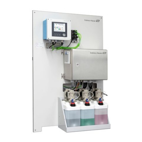
Liquiline Control CDC90 Product description Product description System structure A complete measuring system comprises the following components: • CDC90 control unit • Pneumatic control unit • Canister pump unit The system is available in different versions. Here is a complete overview comprising all of the system' s modules. -
Page 10: Overview Of Pneumatic Control Unit
Product description Liquiline Control CDC90 Overview of pneumatic control unit A0031834 2 Pneumatic control unit Pilot valve manifold, bus node Actuator terminal Compressed air Output interface terminal F1 fuse of the pneumatic control unit and CDC90 control Pressure switch... -
Page 11: Incoming Acceptance And Product
Liquiline Control CDC90 Incoming acceptance and product identification Incoming acceptance and product identification Incoming acceptance 1. Verify that the packaging is undamaged. Notify the supplier of any damage to the packaging. Keep the damaged packaging until the issue has been resolved. -
Page 12: Scope Of Delivery
Incoming acceptance and product identification Liquiline Control CDC90 5. Click on the product image in the popup window. A new window (Device Viewer) opens. All of the information relating to your device is displayed in this window as well as the product documentation. -
Page 13: Installation
Liquiline Control CDC90 Installation Installation Installation conditions The device is intended for wall mounting. Wall mounting as: Panel 5.1.1 Installation site Note the following when erecting the device: 1. Make sure that the wall has sufficient load-bearing capacity and is fully perpendicular. - Page 14 Installation Liquiline Control CDC90 5.2.2 Dimensions of pneumatic control unit 210 (8.27) 380 (15.0) A0031929 4 Dimensions of pneumatic control unit in mm (in) 5.2.3 Dimensions of canister holder 160 (6.3) 150 (5.9) 8.5 (0.33) Ø 470 (18.50) 220 (8.66) A0033139 ...
- Page 15 Liquiline Control CDC90 Installation 65 (2.56) 140 (5.51) 151 (5.94) 190 (7.48) A0032277 6 Dimensions of canister with pump in mm (in) 5.2.4 Dimensions of rinsing block and changeover valve 195 (7.68) 120 (4.72) 108 (4.25) 181 (7.13) 223.5 (8.80) A0032267 ...
-
Page 16: Wall Mounting
Installation Liquiline Control CDC90 5.2.5 Dimensions of mounting plate 770 (30.31) 8 (0.31) 8 (0.31) 150 (6.00) 380 (15.00) 20 (0.79) 600 (23.62) 86 (3.39) A0031946 9 Dimensions of mounting plate in mm (in) Wall mounting CAUTION Risk of injury The weight of the unit may result in crush injuries or other injuries. -
Page 17: Maximum Hose And Cable Length For One Measuring Point
Liquiline Control CDC90 Installation Maximum hose and cable length for one measuring point In the diagram below you will see the maximum length of the hose and cable between the system components. 0.5-2* (1.64-6.56) A0032617 10 Maximum distances between the system components in m (ft) -
Page 18: Securing Rinsing Block To Assembly
Installation Liquiline Control CDC90 Securing rinsing block to assembly CAUTION Risk of injury Crush injuries or other injuries may occur. ‣ Use a suitable mounting tool, for example an Allen key. Rinsing block bracket to assembly A0032669 1. Fit one half of the rinsing block bracket (1) on the assembly cylinder. -
Page 19: Mounting The Changeover Valve For The 2Nd Measuring Point
Liquiline Control CDC90 Installation Connecting to rinsing block valve A0032739 1. Unscrew the head of the valve. 2. Remove the head and the clamping ring positioned underneath. 3. Guide the hose through the head and the clamping ring into the valve. -
Page 20: Mechanical Connection
Installation Liquiline Control CDC90 A0033445 Connect the two parts using the screws provided. Mechanical connection CAUTION Very loud pumps The noise from the pumps can hurt the ears. ‣ Wear ear protectors in the vicinity of the pumps. 5.8.1 Connecting medium and compressed air... - Page 21 Liquiline Control CDC90 Installation A0031871 12 Hose connection diagram for medium and compressed air for 1st measuring point Pumps 1-3 Process valve Buffer solutions and cleaner Water connection Assembly (measuring/service) Liquid Rinsing block Compressed air Pilot valve manifold in pneumatic control unit The individual hoses are grouped together in multihoses.
- Page 22 Installation Liquiline Control CDC90 5.8.2 Connecting compressed air supply Compressed air supply When connecting, please pay attention to the following: • The compressed air line is to be provided by the customer. • The air pressure is 4 to 6 bar (58 to 87 psi).
- Page 23 Liquiline Control CDC90 Installation 5.8.3 Connecting multihoses M1- air hoses from the pneumatic control unit to the rinsing block and assembly M1 connection in the pneumatic control unit The air hoses for the pilot valves are located in the hose package of the M1 multihose.
- Page 24 Installation Liquiline Control CDC90 Hose 1 I, measure position Hose 2 O, service position CPA471/472/475 Hose 1 Upper connection Hose 2 Lower connection Connecting assembly CPA473/474 A0033220 7. Connect the hoses as follows: Hose number: Connection on assembly: Hose 1...
- Page 25 Liquiline Control CDC90 Installation A0033922 15 Connection of float switch M2 connection to rinsing block 2. Connect the hoses from the pumps to the valves of the rinsing block as follows: A0033438 Hose number Function Cleaner Buffer 1 Buffer 2...
- Page 26 Installation Liquiline Control CDC90 M3 (2nd measuring point)- air hoses from the pneumatic control unit to the changeover valve and assembly of the 2nd measuring point M3 connection to the pneumatic control unit The hose package of the M3 multihose contains the following hoses: •...
- Page 27 Liquiline Control CDC90 Installation Hose number Function Compressed air control for assembly, measuring Retraction of assembly, service 5.8.4 Rinsing line on rinsing block A0032651 16 Rinsing block Cleaner (pump 1) Air rinsing block (pilot valve 4) Buffer 2 (pump 3)
- Page 28 Installation Liquiline Control CDC90 A0033443 18 Rinsing block with two assemblies (1st and 2nd measuring point) 1. Rinse the pipe thoroughly. 2. Connect the rinse water (7) to the water connection (6) of the rinsing block. 3. Connect the rinse chamber connection (4) on the rinsing block (5) to the rinse connection (3) of the changeover valve (2).
-
Page 29: Post-Installation Check
Liquiline Control CDC90 Installation Installation option 1 Installation option 2 M S 1 MS 2 M S 1 MS 2 A+B=max 10 m A+B= max 10 m A+C= max 10 m 1 = Pneumatic control unit 2 = Rinsing block... - Page 30 Installation Liquiline Control CDC90 5. Verify that all multihoses are positioned in such a way that they are protected. Endress+Hauser...
-
Page 31: Electrical Connection
Liquiline Control CDC90 Electrical connection Electrical connection Connection conditions NOTICE The device does not have a power switch ‣ A fuse with a maximum rating of 16 A must be provided by the customer. Observe the local regulations for installation. - Page 32 Electrical connection Liquiline Control CDC90 6.2.1 Cable gland assignment A0033181 20 CDC90 control unit cable gland Wiring Designation Assignment CDC90 control unit supply voltage EtherNet Sensor, 1st measuring point Sensor, 2nd measuring point Sensor, float switch, pressure switch, IPC power supply 6.2.2...
- Page 33 Liquiline Control CDC90 Electrical connection Slot 6 Port 1 Pin 47 128/SW Service A0031940 21 Example of port assignment 6.2.3 Opening the CDC90 control unit NOTICE Pointed or sharp tools If unsuitable tools are used, they can scratch the housing or damage the seal, and thus have a negative impact on the leak-tightness of the housing! ‣...
- Page 34 Electrical connection Liquiline Control CDC90 6.2.4 Cable mounting rail A0025171 24 Cable mounting rail and associated function Cable mounting rail Additional threaded bolts for ground connections Threaded bolt (protective ground connection, Cable clamps (fixing and grounding the sensor central grounding point) cables) 6.2.5...
- Page 35 Liquiline Control CDC90 Electrical connection 6.2.6 Cable terminals Plug-in terminals for Memosens and PROFIBUS/RS485 connections ‣ ‣ Insert the cable until the limit ‣ Press the screwdriver against Remove the screwdriver (closes stop. the clip (opens the terminal). the terminal).
-
Page 36: Connecting The Sensors
Electrical connection Liquiline Control CDC90 Connecting the sensors 6.3.1 Sensor types Sensors with Memosens protocol Sensor types Sensor cable Sensors Digital sensors without additional internal With plug-in connection and inductive signal • pH sensors power supply transmission • ORP sensors A0033455 ‣... -
Page 37: Connecting Additional Inputs And Outputs
Liquiline Control CDC90 Electrical connection Connecting additional inputs and outputs WARNING Module not covered No shock protection. Danger of electric shock! ‣ Change or extend the hardware: always fill the slots from left to right. Do not leave any gaps. - Page 38 Electrical connection Liquiline Control CDC90 6.4.2 Current inputs Module 2AI – – 31 Module 32 Wiring diagram Input for control signal from soft keys. The second input can also be used to control the implementation of the program remotely.
-
Page 39: Connecting Digital Communication
Liquiline Control CDC90 Electrical connection Connecting digital communication 6.5.1 Connecting the EtherNet The connected external devices must be insulated against dangerous voltage that may occur. A0033466 In the CDC90 control unit, connect the EtherNet adapter cable W19 to the ETH module. - Page 40 Electrical connection Liquiline Control CDC90 Connecting the EtherNet switch communication cable A0033473 1. Connect the communication cable (W22) for the EtherNet switch (1) to the connection (2). 2. Guide the cable through cable gland "4" of the pneumatic control unit. → 42 3.
- Page 41 Liquiline Control CDC90 Electrical connection Terminal XL Cable wire Brown Blue Gray LED ETH module 128/SW Service 36 Wiring 35 Module diagram LEDs on front of module Identifier Color Description RJ45 LNK/ACT • Off = Connection is not active •...
-
Page 42: Connecting The Pneumatic Control Unit
Electrical connection Liquiline Control CDC90 Connecting the pneumatic control unit 6.6.1 Cable gland assignment 1 2 3 4 5 9 10 11 12 A0033199 37 Pneumatic control unit cable gland Assignment Wiring Designation Signal cable actuator Power supply cable of CDC90 control unit... - Page 43 Liquiline Control CDC90 Electrical connection Terminal X2, top Cable wire Function W6, BN Float switch, buffer 2 W7, BK Pressure switch W7, BN Pressure switch 6.6.3 Assemblies CDC90 is designed for the following assemblies: • Cleanfit CPA47x • CPA871/CPA875 Limit position switches...
- Page 44 Electrical connection Liquiline Control CDC90 Output interface terminal T2, Cable wire Function bottom Pin 1 W25, BN Lower limit position switch Pin 2 W25, BU Lower limit position switch Cleanfit CPA473/CPA474 Assemblies with a pneumatic limit position switch will be retrofitted with electrical switches.
- Page 45 Liquiline Control CDC90 Electrical connection Cleanfit CPA8x Assembly monitoring A0032753 40 Position feedback signal, CPA87... Feedback cable A0017831 Limit position switch, service position Limit position switch, measuring position Connector, M12, solder side (inside of assembly) Coding Connector, Pin side (outside of assembly) A0022163 ...
-
Page 46: Connecting The Main Supply Voltage
Electrical connection Liquiline Control CDC90 Connection at output interface terminal in the pneumatic control unit Output interface terminal T1, Cable wire Function bottom Pin 1 W2, BK Limit position switch, confirmation of position Pin 2 W2, BU Limit position switch, confirmation of... -
Page 47: Ensuring The Degree Of Protection
Liquiline Control CDC90 Electrical connection Terminal X1, bottom Cable wire L1, BN PE, GN-YE N, BU PE PE PE PE PE PE PE PE PE PE PE PE PE A0035338 42 Terminal diagram of main supply voltage of actuator terminal X1 in the pneumatic control unit... -
Page 48: Post-Connection Check
Electrical connection Liquiline Control CDC90 Post-connection check WARNING Connection errors The safety of people and of the measuring point is at risk! The manufacturer does not accept any responsibility for errors that result from failure to comply with the instructions in this manual. -
Page 49: System Integration
Liquiline Control CDC90 System integration System integration Web server 7.1.1 Establishing the data connection 1. Start the PC. 2. First, configure a manual IP address in the network connection settings of the operating system. 3. Start the browser. 4. If you use a proxy server to connect to the Internet: Disable the proxy (browser settings under "Connections/LAN settings"). - Page 50 System integration Liquiline Control CDC90 Amber Blue RJ45 assignment to M12 connection RJ45 Yellow White Amber Blue More detailed information on fieldbus communication is provided on the product pages on the Internet: • EtherNet/IP: SD02511C • Modbus: SD02512C • PROFIBUS DP: SD02513C •...
-
Page 51: Operation Options
Liquiline Control CDC90 Operation options Operation options Overview 8.1.1 Display and operating elements A0031833 43 Overview of operation Touchscreen display LED light Soft keys (function selectable) Green A program is active System error. Programs do not start. Flashing red System malfunction. -
Page 52: Access To The Operating Menu Via The Local Display
Operation options Liquiline Control CDC90 Access to the operating menu via the local display 8.2.1 Operating concept A0033711 The CDC90 can be operated via a touchscreen display. Soft keys are also available for program operation. 8.2.2 Assigning soft keys The soft keys are preconfigured with program IDs 801 to 804. See the Configuration tool/ Programs section. - Page 53 Liquiline Control CDC90 Operation options 8.2.3 Menu overview A0033714 Item Function Date and time Display of and fast access to the most important error message with settings Display and navigation to measuring point 1 In 1-channel devices: second measured value of measuring point 1...
-
Page 54: Access To The Operating Menu Via The Web Browser
Operation options Liquiline Control CDC90 A0041515 44 Overview System overview Overview of measuring point 1 Overview of measuring point 2 Active program Upcoming programs Access to the operating menu via the Web browser The same menu options are available via the web server as for the onsite display. -
Page 55: Commissioning
Liquiline Control CDC90 Commissioning Commissioning Preparatory steps 9.1.1 Filling the canisters ‣ Fill the canisters as follows from left to right: Canister (left to Content right) Cleaner Buffer 1 Buffer 2 We recommend you replace the buffers every 6 months. Pay attention to the expiry date on the canister. -
Page 56: Switching On The Measuring Device
Commissioning Liquiline Control CDC90 NOTICE Unmonitored activated pumps, valves or similar. Damage to devices. ‣ Perform the installation and function check. ‣ Ensure that all moving parts are correctly mounted. Operate the system only using liquids with a conductivity of > 10 nS/cm. -
Page 57: Configuring The Measuring Device
Liquiline Control CDC90 Commissioning Item Function Play and stop button for programs. Control only possible if buttons are activated. Measuring or service position of assembly Valve (water or air) closed or open Color representation of the active medium, depending on the program... - Page 58 Commissioning Liquiline Control CDC90 9.4.4 Communication User role: Maintenance Operating mode: Setup → 62 Path:System configurationt/Information Function Options Info Modbus Information Modbus Transmission of Modbus information (communication to DCS) For detailed information on "Modbus Byte order: communication", see the product...
- Page 59 Liquiline Control CDC90 Commissioning → 62 Path:System configurationt/Information Function Options Info Valves Switching operations and warning Warning limit settings for the pilot limits of: valves. • Water valve • Air valve • Changeover valve • Selectable valve 1 to 5 9.4.7...
- Page 60 Commissioning Liquiline Control CDC90 9.4.10 Starting commissioning Initial commissioning is performed by Endress+Hauser specialists. Endress+Hauser...
-
Page 61: Operation
Liquiline Control CDC90 Operation Operation 10.1 Reading measured values Path:Visualization/Measuring Point 1 or Measuring Point 2 A0041431 45 Sample overview of a measuring point Item Function Shortcut to measuring point overview Measuring point 1 or 2 Main values Assembly type Assembly position 10.2... - Page 62 Operation Liquiline Control CDC90 Overview of user roles User role Function Admin Switch user administration on and off Change password Maintenance System operation Schedule programs Configure the entire system Change the operating mode Operator System operation Schedule programs Configure the main functions of the system...
- Page 63 Liquiline Control CDC90 Operation Steps • Certain actions concerning sensor cleaning and/or calibration are divided into individual steps. A step defines: • The state of the outputs (valves, DO). • The state of the inputs (DI). • Steps 1-14 are preset, but users can define their own customized steps in steps 15-20.
- Page 64 Operation Liquiline Control CDC90 Name Function Cleaner Pumps medium from canister 1 (default: cleaner) for the indicated period of time. Then stops afterwards Buffer 1 Pumps medium from canister 2 (default: buffer 1) for the indicated period of time. Then stops afterwards...
- Page 65 Liquiline Control CDC90 Operation Assembly Output/valves Input Is set to "ON" at the start of a step. Step triggers an error if the Returns to the original state at the input is not set to "ON" at the end of the step.
- Page 66 Freely available All sequences can be modified/optimized and reused within sequences. Non-configured sequences are also available. Standard buffer 1 is Endress+Hauser' s pH 7 buffer. Standard buffer 2 is Endress+Hauser' s pH 4 buffer. Measuring point assignment of sequences The assignment of the sequences to a measuring point is controlled via the "Program"...
- Page 67 Liquiline Control CDC90 Operation A0041444 47 Programming in the configuration tool Program ID Name of the program Sequ Sequence contained in the program ence Chan Measuring point assignment 1. Open the configuration tool. 2. Select the Programs tab. 3. Under Programs, select the desired sequence in Sequence.
- Page 68 Operation Liquiline Control CDC90 Importing or exporting the configuration tool User role: Maintenance Operating mode: Setup The following configurations can be imported or exported: Programs Settings for the programs.. System configurationt Data for system configuration Device configuration Settings, e. g. warning limits, for the devices...
- Page 69 Liquiline Control CDC90 Operation 6. Select Next and then Finish to quit the assistant. The program is not stopped. Explanation of buttons Play button magenta The program can be started Play button blue The program is running Stop button magenta...
- Page 70 Operation Liquiline Control CDC90 10.2.9 Current outputs Current outputs can only be configured with an external display or via the web server of the CM44 transmitter Please contact your Endress+Hauser sales organization for the configuration of the current outputs. Endress+Hauser...
-
Page 71: Diagnostics And Troubleshooting
Liquiline Control CDC90 Diagnostics and troubleshooting Diagnostics and troubleshooting 11.1 General troubleshooting 11.1.1 Simulating the inputs and outputs You can simulate pilot valves and outputs for test purposes, e.g.: • Opening or closing of the pilot valves for the assembly position or the pumps •... - Page 72 Diagnostics and troubleshooting Liquiline Control CDC90 11.2.2 Device-specific, general diagnostic messages Error number Troubleshooting Error message 1000 Communication between the controller and valve manifold is interrupted ‣ Check the connection between the devices. 1001 Communication between the controller and transmitter is interrupted.
- Page 73 Liquiline Control CDC90 Diagnostics and troubleshooting Error number Troubleshooting Error message 1401 Invalid step in program. ‣ Correct the program. 1402 Error in calibration. 1500 Warning limit for movements exceeded. The assembly must be serviced. 1501 Assembly position not defined.
- Page 74 Diagnostics and troubleshooting Liquiline Control CDC90 Error number Troubleshooting Error message Sensor communication blocked Sensor not ready Sensor fails tag check. Replace. Internal software error. Contact the Service Department. Temperature sensor defective Temperature sensor ‣ Replace the sensor. Sensor electronics defect Sensor electronic ‣...
- Page 75 Liquiline Control CDC90 Diagnostics and troubleshooting Error number Troubleshooting Error message Leak current alarm Sensor leakage Defective due to abrasion or damage Damage to the gate (only ISFET) ‣ Replace the sensor. Leak current warning Sensor leakage Measuring can continue until the...
- Page 76 Diagnostics and troubleshooting Liquiline Control CDC90 Error number Troubleshooting Error message Max. zero point warning, Sensor calibration measurement can still take place Possible reasons: sensor old or defective, reference blocked, calibration solution too old or contaminated Check or replace sensor.
-
Page 77: Event Logbook
Liquiline Control CDC90 Diagnostics and troubleshooting Error number Troubleshooting Error message Min. operating point warning, Sensor calibration measurement can still take place Possible reasons: sensor old or defective, reference blocked, calibration solution too old or contaminated Check or replace sensor. -
Page 78: Resetting The Measuring Device
Diagnostics and troubleshooting Liquiline Control CDC90 The following values are displayed: • Measuring point • Parameter • Sensor serial number • Sensor-specific calibration data • Number of measuring points • Results 11.3.2 Diagnostic events Lists of diagnostic events. Select a particular event to display more detailed information. -
Page 79: Maintenance
Liquiline Control CDC90 Maintenance Maintenance WARNING Process pressure and temperature, contamination, electrical voltage Risk of serious or fatal injury ‣ If the sensor has to be removed during maintenance work, avoid hazards posed by pressure, temperature and contamination. ‣ De-energize the device before you open it. - Page 80 Maintenance Liquiline Control CDC90 NOTICE Cleaning agents not permitted Damage to the housing surface or housing seal ‣ Never use concentrated mineral acids or alkaline solutions for cleaning. ‣ Never use organic cleaners such as acetone, benzyl alcohol, methanol, methylene chloride, xylene or concentrated glycerol cleaner.
- Page 81 Liquiline Control CDC90 Maintenance 3. If no damage is found, regenerate the sensor. Where necessary, store the sensor in a regeneration solution (→ sensor manual). 4. Recalibrate the sensor for reuse. 12.1.3 Assemblies Refer to the assembly operating manual for information on servicing and troubleshooting the assembly.
- Page 82 Maintenance Liquiline Control CDC90 5. Screw the float switch into the canister. 12.1.5 Cables, connections and power supply lines Weekly Monthly Biannually ‣ Check the leak-tight If the assembly is Check if the interior and circuit boards condition of: located in a wet are clean, dry and free from corrosion.
-
Page 83: Repair
Liquiline Control CDC90 Repair Repair 13.1 General notes ‣ Only use spare parts from Endress + Hauser to guarantee the safe and stable functioning of the device. Detailed information on the spare parts is available at: www.endress.com/device-viewer ‣ Following repairs, check that the device is complete, in a safe condition and functioning correctly. - Page 84 Repair Liquiline Control CDC90 Item Order no. Kit CDC90 air filter 71361218 Kit CDC90 wall holder unit V4A 71361219 Kit CDC90 wall holder unit, steel, coated 71361220 Kit CDC90 8-valve manifold 71361221 Kit CDC90 16-valve manifold 71361222 Kit CDC90 valve module x 2 (NC) for all other actuators...
-
Page 85: Return
The product must be returned if repairs or a factory calibration are required, or if the wrong product was ordered or delivered. As an ISO-certified company and also due to legal regulations, Endress+Hauser is obliged to follow certain procedures when handling any returned products that have been in contact with medium. - Page 86 Accessories Liquiline Control CDC90 Cleanfit CPA472 • Compact plastic retractable assembly for installation in tanks and pipes • For manual or pneumatic, remote-controlled operation • Product Configurator on the product page: www.endress.com/cpa472 Technical Information TI00223C Cleanfit CPA472D • Robust retractable assembly for pH, ORP and other industrial sensors •...
-
Page 87: Sensors
Liquiline Control CDC90 Accessories 14.2 Sensors 14.2.1 Glass electrodes Orbisint CPS11D • pH sensor for process technology • Optional SIL version for connecting to SIL transmitter • With dirt-repellent PTFE diaphragm • Product Configurator on the product page: www.endress.com/cps11d Technical Information TI00028C Memosens CPS31D •... -
Page 88: Additional Functionality
Accessories Liquiline Control CDC90 Orbipore CPS92D • ORP electrode with open aperture for media with high dirt load • Product Configurator on the product page: www.endress.com/cps92d Technical Information TI00435C 14.2.3 pH ISFET sensors Memosens CPS47D • Sterilizable and autoclavable ISFET sensor for pH measurement •... -
Page 89: Other Accessories
Liquiline Control CDC90 Accessories Kit, extension module 4AO • 4 x analog output 0/4 to 20 mA • Order No. 71135633 14.4 Other accessories 14.4.1 Cable Memosens data cable CYK10 • For digital sensors with Memosens technology • Product Configurator on the product page: www.endress.com/cyk10... - Page 90 • Order No. 71185296 14.4.5 Buffer solutions High-quality buffer solutions from Endress+Hauser - CPY20 The secondary buffer solutions have been referenced to primary reference material of the PTB (German Federal Physico-technical Institute) or to standard reference material of NIST (National Institute of Standards and Technology) according to DIN 19266 by a laboratory accredited by the DAkkS (German accreditation body) according to DIN 17025.
-
Page 91: Technical Data
Liquiline Control CDC90 Technical data Technical data 15.1 Input Measured values → Documentation of the connected sensor Measuring ranges → Documentation of the connected sensor Types of input • Digital sensor inputs for sensors with Memosens protocol • Digital inputs (optional) -
Page 92: Input
Technical data Liquiline Control CDC90 15.4 Input Measured values → Documentation of the connected sensor Measuring ranges → Documentation of the connected sensor Digital inputs, passive in Span pneumatic control unit • High: 11 to 30 V DC • Low: 0 to 5 V DC Nominal input current max. -
Page 93: Output
Liquiline Control CDC90 Technical data 15.5 Output Analog outputs, active in Signal on alarm CDC90 control unit Adjustable, as per NAMUR Recommendation NE 43 • In measuring range 0 to 20 mA: Failure current from 20 to 23 mA • In measuring range 4 to 20 mA: Failure current from 2.4 to 23 mA... - Page 94 Technical data Liquiline Control CDC90 EtherNet/IP Name EtherNet/IP adapter Manufacturer 3S-Smart Software Solutions GmbH Categories EtherNet/IP local adapter EtherNet/IP ODVA certification Device profile Generic device Manufacturer ID 1285 Device type ID 0000 1016 Polarity Auto-MIDI-X Minimum RPI 300 ms (default)
- Page 95 Liquiline Control CDC90 Technical data TCP port Supported features • Remote-controlled device configuration • Save/restore device configuration (via SD card) • Access to web server via Internet browser Endress+Hauser...
-
Page 96: Power Supply
Technical data Liquiline Control CDC90 15.6 Power supply Supply voltage 100 to 230 V AC Frequency 50/60 Hz Power consumption Max. 50 VA Cable specification Power supply cable (mains) Cable cross-section: • Minimum cross-section 3 x 0.75 mm² to 10 m length •... -
Page 97: Performance Characteristics
Liquiline Control CDC90 Technical data 15.7 Performance characteristics Response time Current outputs = max. 500 ms for an increase from 0 to 20 mA Current inputs = max. 330 ms for an increase from 0 to 20 mA Digital inputs and outputs = max. -
Page 98: Mechanical Construction
Technical data Liquiline Control CDC90 Electromagnetic Interference emission and interference immunity as per EN 61326-1:2013, Class A for compatibility Industry Operating altitude Max. altitude above MSL < 2000 m (< 6562 ft) above MSL Pollution degree The product is suitable for pollution degree 2. - Page 99 Liquiline Control CDC90 Technical data Device Material Pump canister unit Pump PVDF+CF/PP/NBR+PTFE/PTFE/PP Canister Float switch PVC/EPDM/PE Canister fitting ABS/PMMA Bracket M5 L110*B40 W8 O-ring EPDM Coupling DMG/8*6 1/4 PVDF Canister shelf Rinsing block Process valve EPDM/PP/stainless steel:1.4408/PTFE Rinsing body PVDF/1.4401...
- Page 100 Technical data Liquiline Control CDC90 Hose diameter Size Medium DN 3/4 mm Compressed air DN 6/8 mm Hose connection nipple Endress+Hauser...
- Page 101 Liquiline Control CDC90 Index Index Ensuring the degree of protection ....47 EtherNet ........39 Accessories .
- Page 102 Index Liquiline Control CDC90 Protocol-specific data ..... . 93 Technical personnel ......6 Pollution degree .
- Page 104 www.addresses.endress.com...