
Related Manuals for Endress+Hauser Cerabar S PMP71 with MID Part Certificate


Summary of Contents for Endress+Hauser Cerabar S PMP71 with MID Part Certificate
- Page 1 Operating Instructions Cerabar S PMP71 with MID Part Certificate Process pressure measurement BA00412P/00/EN/02.12 71185804 Valid for software version: 02.10.54...
- Page 2 – Behavior during operation and in event of failure version "E" in feature 100 "Additional options – Commissioning and iterative tests 1" or in feature 110 "Additional options 2". See – Settings also Technical Information TI00383P, Section – Safety-specific characteristic quantities "Ordering information". – Management summary Endress+Hauser...
-
Page 3: Table Of Contents
Operation via HART handheld terminal ..31 Endress+Hauser operating program ... . 31 Locking/unlocking operation ....31 Factory setting (reset) . -
Page 4: Safety Instructions
• Ensure that all personnel are suitably qualified. 1.3.2 Functional safety SIL3 (optional) If using devices for functional-safety applications, strict compliance with the Functional Safety Manual (SD00190P) is mandatory. Endress+Hauser... -
Page 5: Notes On Safety Conventions And Icons
Connecting cable immunity to temperature change t >85°C Indicates that the connecting cables have to withstand a temperature of 85 °C (185 °F) at least. Safety instructions Observe the safety instructions in the associated Operating Instructions. Endress+Hauser... -
Page 6: Identification
Symbol: Note: pay particular attention to the data in "Technical Information"! Minimum/maximum span Nominal measuring range Electronic version (output signal) Wetted materials Supply voltage GL symbol for GL marine certificate (optional) SIL symbol for devices with SIL3/IEC 61508 Declaration of Conformity (optional) Approval marks and ID numbers Manufacturer's address Endress+Hauser... - Page 7 Checksum: 0xD8CC SW Rev. 02.10.54 P01-PMP71MID-18-xx-xx-xx-000 Fig. 4: Additional nameplate for devices suitable for custody transfer applications Maximum pressure for liquid applications Minimum pressure for liquid applications Maximum pressure for gas applications Minimum pressure for gas applications Endress+Hauser...
- Page 8 Maximum temperature for devices suitable for oxygen applications Maximum pressure for devices suitable for oxygen applications 2.1.2 Identifying the sensor type See parameter "Sensor Meas.Type" in Operating Instructions BA00413P. Operating Instructions BA00413P can be found on the supplied CD. Endress+Hauser...
-
Page 9: Scope Of Delivery
The device complies with the applicable standards and regulations as listed in the EC Declaration of Conformity and thus complies with the statutory requirements of the EC Directives. Endress+Hauser confirms the successful testing of the device by affixing to it the CE mark. -
Page 10: Installation
• To ensure optimal readability of the onsite display, it is possible to rotate the housing up to 380°. → ä 14, "Rotating the housing". • Endress+Hauser offers a mounting bracket for installing on pipes or walls. → ä 13, "Wall and pipe-mounting (optional)". - Page 11 • Do not clean or touch process isolating diaphragms with hard or pointed objects. • To comply with ASME-BPE requirements regarding cleanability (Part SD Cleanability), the device must be installed as follows: Pressure measurement in gases ➀ ➁ P01-PMx7xxxx-11-xx-xx-xx-001 Fig. 6: Measuring arrangement for pressure measurement in gases Cerabar S Shutoff device Endress+Hauser...
- Page 12 • Fill the siphon with fluid before commissioning. Pressure measurement in liquids ➀ ➁ P01-PMx7xxxx-11-xx-xx-xx-003 Fig. 8: Measuring arrangement for pressure measurement in liquids Cerabar S Shutoff device Mount Cerabar S with shutoff device below or at the same level as the tapping point. Endress+Hauser...
- Page 13 The seal is not allowed to press against the process isolating diaphragm as this could affect the measurement result. 3.3.3 Wall and pipe-mounting (optional) Endress+Hauser offers a mounting bracket for installing on pipes or walls. mm (in) P01-xMx5xxxx-06-xx-xx-xx-001 Please note the following when mounting: •...
-
Page 14: Post-Installation Check
These screws should be hand-tightened (2 Nm, 1.48 lbf ft) to the stop to ensure that the covers sit tightly. Post-installation check After installing the device, carry out the following checks: • Are all the screws firmly tightened? • Are the housing covers screwed down tight? Endress+Hauser... -
Page 15: Wiring
Minimum supply voltage = 10.5 V DC, jumper is inserted in accordance with the illustration. Minimum supply voltage = 11.5 V DC, jumper is inserted in "Test" position. Devices with integrated overvoltage protection are labeled OVP (overvoltage protection) here. Endress+Hauser... - Page 16 Fig. 13: Left: electrical connection for devices with Harting connector Han7D Right: view of the connection at the device 4.1.2 Devices with M12 connector PIN assignment for M12 connector Meaning signal + – not used signal – ground A0011175 Endress+Hauser...
-
Page 17: Connecting The Measuring Unit
– Minimum supply voltage: 10.5 V DC 4.2.2 Cable specification • Endress+Hauser recommends using twisted, shielded two-wire cables. • Terminals for wire cross-sections 0.5 to 2.5 mm (20 to 14 AWG) • Cable outer diameter: 5 to 9 mm (0.2 to 0.35 in) - Page 18 • When using in hazardous areas, you must observe the applicable regulations. Separate Ex documentation with additional technical data and instructions is included with all Ex devices as standard. Endress+Hauser...
- Page 19 FieldCare Commubox FXA291 The Commubox FXA291 connects Endress+Hauser field devices with a CDI interface (= Endress+Hauser common data interface) to the USB port of a personal computer or a notebook. For details, refer to TI00405C/07/EN. Note! You will also require the following accessory for the device: "ToF Adapter FXA291".
-
Page 20: Potential Equalization
• Are all the screws firmly tightened? • Are the housing covers screwed down tight? As soon as voltage is applied to the device, the green LED on the electronic insert lights up for a few seconds or the connected onsite display lights up. Endress+Hauser... -
Page 21: Operation
• Rapid and safe commissioning with the Quick Setup menus Parameter Measured value display Identification Function name Value number Header line Main line Unit Information line Symbol – Bargraph Bargraph Editing modes Operating keys Selection options Value that can be edited Current measured value P01-xMx7xxxx-07-xx-xx-xx-001 Endress+Hauser... -
Page 22: Operating Elements
Lead sealing of the housing cover is provided (→ ä 37) for use in applications subject to custody transfer regulations. The DIP switch must be used to block access to the electronics and lock configuration of the device. DIP switch for damping on/off Green LED to indicate value being accepted Endress+Hauser... - Page 23 – You are in a menu at a selection level. Each time you press the keys simultaneously, you go up a level in the menu. Note: The terms function group, level and selection level are explained in → ä 25, "General structure of the operating menu". Endress+Hauser...
-
Page 24: Onsite Operation - Onsite Display Not Connected
Observe the input Observe the input Observe the input limits. limits. limits. Please note warning on Page → ä 34, "Commissioning". Endress+Hauser... -
Page 25: Onsite Operation
1st selection level. In digital communication, the LANGUAGE parameter is displayed in the DISPLAY group and the MEASURING MODE parameter is displayed in the QUICK SETUP menus or in the BASIC SETUP function group. → ä 52, "Operating menu for onsite display and digital communication". Endress+Hauser... - Page 26 The decimal point is highlighted in black, i.e. you can now edit it. P01-xxxxxxxx-19-xx-xx-xx-029 1. Keep pressing "+" or "–" until "0" is displayed. 2. Confirm "0" with "E". The cursor goes to the next position. ↵ is displayed and highlighted in black. → See next graphic. P01-xxxxxxxx-19-xx-xx-xx-030 Endress+Hauser...
-
Page 27: Historom®/M-Dat (Optional)
• Recording diverse events, such as alarms, configuration changes, counters for measuring range undershooting and overshooting for pressure and temperature, overshooting and undershooting the user limits for pressure and temperature, etc. Warning! ® Detach HistoROM /M-DAT from the electronic insert or attach it to the insert in a de-energized state only. Endress+Hauser... - Page 28 Press the "E" and "-" keys (for at least 3 seconds) until the LED on the electronic insert lights up. ® Wait approx. 20 seconds. Configuration data are loaded from the device to the HistoROM M-DAT. The device is not restarted. Disconnect device from the supply voltage again. Detach memory module. Reestablish supply voltage to the device. ´ Endress+Hauser...
- Page 29 ® Wait approx. 20 seconds. Configuration data are loaded from the device to the HistoROM M-DAT. The device is not restarted. Disconnect device from the supply voltage again. Detach memory module. Reestablish supply voltage to the device. Endress+Hauser...
- Page 30 (Menu path: (GROUP SELECTION →) OPERATING MENU → OPERATION) ® Wait approx. 20 seconds. Configuration data are loaded from the device to the HistoROM M-DAT. The device is restarted. ® Before removing the HistoROM /M-DAT again from the electronic insert, disconnect the device from the supply voltage. Endress+Hauser...
-
Page 31: Operation Via Hart Handheld Terminal
FieldCare is an Endress+Hauser asset management tool based on FDT technology. With FieldCare, you can configure all Endress+Hauser devices as well as devices from other manufacturers that support the FDT standard. Hardware and software requirements can be found on the Internet: www.endress.com →... - Page 32 OPERATING MENU → OPERATION → INSERT PIN NO. 2. To lock operation, enter a number for this parameter between 0 and 9999 that is ≠100. Unlocking operation 1. Select INSERT PIN NO. parameter. 2. To unlock operation, enter "100" for the parameter. Endress+Hauser...
-
Page 33: Factory Setting (Reset)
Note! Any customer-specific configuration carried out by the factory is not affected by a reset (customer- specific configuration remains). If you want to change the customer-specific configuration set at the factory, please contact Endress+Hauser Service. Reset code Description and effect... -
Page 34: Commissioning
See also → ä 25, "General structure of the operating menu". The following languages are available: • Deutsch • English • Français • Italiano • Español • Nederlands • Chinese (CHS) • Japanese (JPN) The following measuring modes are available: • Pressure Endress+Hauser... -
Page 35: Position Adjustment
To correct the MEASURED VALUE to 0.0 mbar, you must enter the value 2.2 here. (MEASURED VALUE = MEASURED VALUE – CALIB. OFFSET) – MEASURED VALUE (after entry for calib. offset) = 0.0 mbar – The current value is also corrected. Factory setting: Endress+Hauser... -
Page 36: Pressure Measurement
Due to orientation of the device, there may be a shift in the measured value. For the POS. INPUT VALUE the measured value. For the POS. INPUT VALUE parameter, specify the desired set point for the parameter, specify the desired set point for the MEASURED VALUE. MEASURED VALUE. Endress+Hauser... -
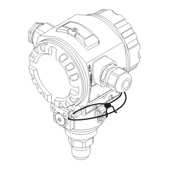
Page 37: Lead Sealing Plan
→ ä 23, "Function of the operating elements – onsite display connected" and → ä 25, "Onsite operation – onsite display connected". Lead sealing plan Lead sealing of the housing cover is provided for use in applications subject to custody transfer regulations: P01-MIDxxxxx-19-xx-xx-xx-031 Endress+Hauser... -
Page 38: Maintenance
• The cleaning agents used should not corrode the surface and the seals. • Mechanical damage to the process isolating diaphragm, e.g. due to pointed objects, must be avoided. • Observe the degree of protection. See the nameplate if necessary (→ ä 6). Endress+Hauser... -
Page 39: Troubleshooting
• If the device detects a defect in the onsite display during initialization, special error messages are generated. For error messages, see → ä 45, "Onsite display error messages". • For support and further information, please contact Endress+Hauser Service. • See also "Repair", "Repair of Ex-certified devices" and "Spare Parts". - Page 40 Spans for the "Height linearized" option: LEVEL MAX. – LEVEL MIN.; TANK CONTENT MAX. – TANK CONTENT MIN. 613 (W613) Warning I>Simulation is active – Simulation is switched on, i.e. the – Switch off simulation. device is not measuring at present. Endress+Hauser...
- Page 41 – Carry out calibration again. (See also limits. linearization table is either below Operating Instructions BA00413P, the value for HYDR. PRESS MIN. or Section 5 or these Operating MIN. LEVEL or above the value for Instructions) HYDR. PRESS. MAX. or LEVEL MAX. Endress+Hauser...
- Page 42 B>Y-VAL of lin. table out of edit – At least one Y-VALUE in the – Carry out calibration again. (See also limits linearization table is below the MIN. Operating Instructions BA00413P, TANK CONTENT or above the Section 5 or these Operating MAX. TANK CONTENT. Instructions) Endress+Hauser...
- Page 43 – Briefly disconnect device from the power supply. – Main electronics defective. – Replace main electronics. 729 (A729) Alarm B>RAM error – Fault in the main electronics. – Briefly disconnect device from the power supply. – Main electronics defective. – Replace main electronics. Endress+Hauser...
- Page 44 – Briefly disconnect device from the power supply. – Main electronics defective. – Replace main electronics. 741 (A741) Alarm B>TANK HEIGHT out of edit – LEVEL MIN or LEVEL MAX has – Perform reset (Code 2710) and carry limits been changed. out calibration again. Endress+Hauser...
- Page 45 If the device detects a defect in the onsite display during initialization, the following error messages can be displayed: Message Measure Initialization, VU Electr. Defect A110 Exchange onsite display. Initialization, VU Electr. Defect A114 Initialization, VU Electr. Defect A281 Initialization, VU Checksum Err. A110 Initialization, VU Checksum Err. A112 Initialization, VU Checksum Err. A171 Endress+Hauser...
-
Page 46: Response Of Outputs To Errors
122 for "Sensor not connected". number such as 613 for "Simulation is number such as 731 for "URV user limits active". exceeded". Menu path: (GROUP SELECTION →) OPERATING MENU → OUTPUT Menu path: (GROUP SELECTION →) OPERATING MENU → MESSAGES Endress+Hauser... - Page 47 – Lower sensor limit undershot (E 120 "Sensor low pressure"): 3.6 mA – Upper sensor limit overshot (E 115 "Sensor overpressure"): current output assumes the value set via the SET MAX ALARM parameter. Factory setting: ALT. CURR. OUTPUT: normal Endress+Hauser...
-
Page 48: Confirming Messages
(→ ä 39). Once you have suppressed this message using the F key, the message with the next highest priority is displayed. You can use the F key to suppress each message, one after the other. The ALARM STATUS parameter continues to display all the messages present. Endress+Hauser... -
Page 49: Repair
Cerabar S PMP71 with 4 to 20 mA HART Troubleshooting Repair The Endress+Hauser repair concept provides for measuring devices to have a modular design and that the customer may also carry out repairs (→ ä 50, "Spare Parts"). Note! • For certified devices, please refer to the "Repair of Ex-certified devices" Section. -
Page 50: Spare Parts
Select the required spare parts (You may also use the overview drawing on the right side of the screen.). When ordering spare parts, always quote the serial number indicated on the nameplate. As far as necessary, the spare parts also include replacement instructions. Endress+Hauser... -
Page 51: Return
The measuring device must be returned if repairs or a factory calibration are required, or if the wrong measuring device has been ordered or delivered. According to legal regulations, Endress+Hauser, as an ISO-certified company, is required to follow certain procedures when handling returned products that are in contact with medium. -
Page 52: Appendix
PRESS. ENG. UNIT parameter. These parameters are indicated with a "*". • For a description of the parameters, please refer to Operating Instructions BA00413P "Description of device functions". The exact dependency of individual parameters on one another is explained here. Endress+Hauser... - Page 53 There are parameters that are only displayed if other parameters are appropriately configured. For example the CUSTOMER UNIT P parameter is only displayed if the "User unit" option was selected for the PRESS. ENG. UNIT parameter. These parameters are indicated with a "*". P01-MIDxxxxx-19-xx-xx-EN-025 Endress+Hauser...
- Page 54 PMP71 with MID) SET URV DAMPING VALUE CONF. PASSWORD There are parameters that are only displayed if other parameters are 2) Display via appropriately configured. HART handheld terminal only These parameters are indicated with a "*". See Safety Manual SD00190P. P01-MIDxxxxx-19-xx-xx-en-032 Endress+Hauser...
- Page 55 NR OF REMOTE SEAL 4 TH VALUE FILL FLUID 2) Display via FieldCare and HART handheld terminal only There are parameters that are only displayed if other parameters are appropriately configured. These parameters are indicated with a "*". P01-MIDxxxxx-19-xx-xx-en-033 Endress+Hauser...
- Page 56 Pressure Level Tank content Current SIM. PRESSURE SIM. LEVEL SIM. TANK CONT. SIM. CURRENT SIM. ERROR NO. There are parameters that are only displayed if other parameters are appropriately configured. These parameters are indicated with a "*". P01-PMx7xxxx-19-xx-xx-xx-044 Endress+Hauser...
- Page 57 Cerabar S PMP71 with 4 to 20 mA HART Appendix Endress+Hauser...
-
Page 58: Index
Operating elements, position ..... . 22 Operating keys, position ......22 Endress+Hauser... - Page 59 Cerabar S PMP71 with 4 to 20 mA HART Index Endress+Hauser...
- Page 60 www.endress.com/worldwide BA00412P/00/EN/02.12 71185804 CCS/FM+SGML 9 71185804...