Table of Contents
Advertisement
Quick Links
Advertisement
Table of Contents

Related Manuals for Endress+Hauser CE 4


Summary of Contents for Endress+Hauser CE 4
- Page 1 CE 4 BA 160R/09/en/08.03 51006364 Measurement station Operating instructions...
- Page 2 CE 4 Short overview For quick and simple commissioning. ⇒ Chap. 1, Page 4 Safety notes ⇓ ⇒ Chap. 3, Page 7 Step 1: Install measurement station In this chapter the foundation template, installation levels and hose installation and measurement station installation can be found.
-
Page 3: Table Of Contents
CE 4 Endress+Hauser Table of contents Safety instructions ....4 Technical Data ....29 Correct use . -
Page 4: Safety Instructions
Safety instructions CE 4 Safety instructions Safe and secure use of this measurement station can only be ensured if these operating instructions are read and the safety notes are followed. Correct use The measurement station is designed for automatic online measurement of liquids, not abrasive media. -
Page 5: Returns
Safety instructions Returns Before units are returned to Endress+Hauser for repair, the following must be taken care • The unit should always be accompanied by a completed ’Safety Regulation Form’. Only then can Endress+Hauser transport, check and repair the returned unit. -
Page 6: Identification
This means that each unit delivered will be different: • Analysis system • ASP-Station 2000 water sampler • CE 4 operating instructions • ASP-Station 2000 operating instructions • CE 4 technical instructions • Operating instructions and certificates for the indidual units and components fitted •... -
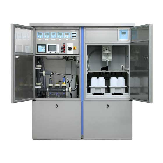
Page 7: Mechanical Installation
CE 4 Mechanical installation Mechanical installation Delivery, transport, storage 3.1.1 Delivery • Is the packaging or content damaged? • If damaged, contact the transport company. 3.1.2 Transport to measurement point The measurement station is delivered mounted on a palette. In order to avoid transport damage, the station is fixed to the pallet in a number of positions. -
Page 8: Installation Conditions
Mechanical installation CE 4 Installation conditions • The permitted ambient temperature (see chapter "Technical data") must not be exceeded both on installation and operation. • A solid foundation must be available. For dimensions see the foundation plan (→ Chap. 3.2.3) •... - Page 9 CE 4 Mechanical installation 3.2.2 Dimensions The dimensions for the measurement station can be found in chapter "Technical data". 3.2.3 Installation point/foundation plan Fig. 4: Foundation drawing without water sampler Pos. A: M8x20 rawl bolts or M8 rawl plugs Pos. B: In and outflow hoses for the measurement liquid Pos.
-
Page 10: Mechanical Installation
Mechanical installation CE 4 3.2.4 Installation point/hose installation Installation hint Sampling point • Medium removal for the pump and the sampling system must be taken from representative point in the channel, i.e. not on the edge of the channel and not in the sump or floor of the channel. - Page 11 CE 4 Mechanical installation 3.3.2 Installation of the measurement station " Caution! • Make sure that the unit is isolated from the mains power when installing or removing the system. Follow the next steps when fitting the measurement station on the foundation: Using the foundation plan as a template, set the rawl bolts or rawl plugs for fixing the station onto the foundation (→...
-
Page 12: Check Installation
Electrical connection CE 4 Check installation Once the unit has been installed, run the following checks: Unit condition and specification Hints Is the measurement station damaged? Visual check Is the rinse water pipe correctly installed and has it been tested for... -
Page 13: Checking The Connections
4 - 20mA signals. 5.1.1 Data storage For data logging, Endress+Hauser can offer a number of different recording and data acquisition devices (e.g. Eco-Graph or Memo-Graph). Fig. 8: Recorders from Endress+Hauser for data storage in the CE 4 measurement station... - Page 14 Operation CE 4 Memo-Graph Eco-Graph Eco-Graph A Paperless recorder for electronic recording Paperless recorder for Functions of this device are of digital and analogue input signals. electronic recording of digital the same as the Eco-Graph, Memo-Graph plots signal sequences, and analogue input signals.
-
Page 15: Commissioning
Compare legend plate and power supply Commissioning the measurement station There are two different types of commissioning of the system- initial commissioning and recommissioning. We recommend the use of an Endress+Hauser service engineer for the initial commissioning process. 6.2.1 Initial commissioning Initial commissioning means the measurement station has not been in use since it was delivered by the manufacturer or the downtime of the system is greater than 4 weeks. -
Page 16: Device Set-Up
Commissioning CE 4 6.2.2 Recommissioning Recommissioning is required when the measurement station is to be made operational after a short time offline (<= 4 weeks). Follow these instructions if the system is to operate safely and reliably: • Make sure that all water connections and internal screw connections are tight •... -
Page 17: Maintenance And Cleaning
CE 4 Maintenance and cleaning Maintenance and cleaning The intervals when the sensors need to be monitored and cleaned are mainly dependent on the features of the medium that is to be measured. It is therefore recommended that during the initial time after commissioning that the sensors are regularly monitored for soiling. - Page 18 Maintenance and cleaning CE 4 Operating the cleaning system Depending on the device configuration the following possibilities are available for manual or automatic cleaning of the pipework: 7.3.1 Manual cleaning using fresh water When using the manual cleaning process the analysis pipework is rinsed, the suction hoses are purged and the sensors are cleaned using a sprayhead and clean water.
- Page 19 CE 4 Maintenance and cleaning If an automatic rinse system is available and the pump is switched on, the complete pipework system including sensors can be rinsed in presettable time cycles using water from the local supply. Rinse cycle and time for hose and sensors must be matched to suit individual application and can be individually set up.
- Page 20 Maintenance and cleaning CE 4 7.3.3 Automatic cleaning system "Chemo-Clean" Cleans the analysis pipework, purge the suction hose and cleans the sensors using a spay head and clean water and chemical cleaning media using the "Chemo-Clean" system. The user selects the cleaning medium (detergent) for the application. The cleaning system control provided using an integrated mini-controller (→...
- Page 21 CE 4 Maintenance and cleaning Sensor rinse: E / F / G Fig. 15: Time cycles for automatic sensor rinse using "Chemo-Clean" Pos. Function Set up address Time interval Factory default Start hose rinse (0...99h) Hose rinse time (0...99s) Pump rinse time (0...99s)
- Page 22 Maintenance and cleaning CE 4 Controller main menu LOGO! starts the programme and indicates the following display: Fig. 17: Display field from the LOGO in RUN Pos. A: Date and time Pos. B: Input condition Pos. C: Output condition A. Date and time on the display: This display flashes until the date and time are set.
- Page 23 CE 4 Maintenance and cleaning Controller set-up menu The LOGO controller recognises 2 operating modes: STOP and RUN. How to stop the programme In order to stop the programme continue as shown: Mo 09:30 06.21.01 Fig. 20: ...Operate ’ESC’, in order to move within the set-up menu...
- Page 24 Maintenance and cleaning CE 4 Select the option 'Set Param' in the set-up menu: Keys Stop >Set Param Set Clock Prg Name Operate the ’OK’ key. LOGO! displays the first paramete. =60:00s =06:00s Pos. A: Block number Pos. B: Display number on functions when using more than one display (not relevant here) Pos.
-
Page 25: Maintenance Plan
CE 4 Accessories Maintenance plan A maintenance plan template that can be filled out can be found in section 10 in the ring binder. Accessories The measurement station is constructed using a number of individual instruments. An itemised parts list is made for each measurement station and placed in the device ring binder. -
Page 26: Fault-Finding
Fault-finding CE 4 Fault-finding Fault-finding instructions Should the measurement station indicate a fault after commissioning or during operation always start fault finding by following the checklists. The user is led to the possible fault and its solution by means of simple questions. -
Page 27: Spare Parts
CE 4 Fault-finding Process faults without messages Fault Possible cause Solution • • No function No power supply Call skilled electrician • Main isolator, fused switches tripped • • Pump does not run or runs only Dry run protection active... -
Page 28: Returns
Fault-finding CE 4 Returns Before returning any device to Endress+Hauser for repair, the following must be taken care of: • The device should always be accompanied by a completed ’Safety Regulation Form’. Only then can Endress+Hauser transport, check and repair the returned device. -
Page 29: Technical Data
CE 4 Technical Data Technical Data 10.1 Inputs 10.1.1 Measurement type and range Endress+Hauser Measurement Ranges Sensor type pH sensor CPS11 pH value and temperature pH: 1 to 12 temperature: -15 to 80 °C Redox sensor CPS12 Redox potential -1000 mV to +1000 mV 10 µS/cm to 20 mS/cm... -
Page 30: Power Supply
Technical Data CE 4 10.3 Power supply 10.3.1 Electrical connection Fig. 22: Fig 3: Measurement station terminal connections - Installation plate in the electronic compartment Pos. A: Terminals, fuses and switch components for the internal wiring. Pos. B: Terminal connection area –... -
Page 31: Operating Conditions
(See Chapter 4.3) Electromagnetic compatibility (EMC) All active electronic devices in the measurement station are CE marked in accordance with the EMC regulations. All Endress+Hauser devices in the measurement station fulfil the requirements laid down in the EN 61326. 10.4.2 Process Medium temperature 0 to 40 °C... -
Page 32: Mechanical Construction
Technical Data CE 4 10.5 Mechanical construction 10.5.1 Design dimensions 1710 1633 Ê Ë A = min. 100 mm Fig. 23: Fig 8: Dimensions in mm – A min. 100 mm wall space for ventilation – Pos. 1: without water sampler –... -
Page 33: Certificates And Approvals
Certificates and approvals 10.6.1 CE mark The device fulfils the legal requirements laid down in the EC directives. Endress+Hauser confirms a successful test of the device by adding the CE mark. 10.6.2 Additional standards and guidelines • EN 60529: Housing protection (IP code) •... -
Page 34: Index
CE 4 Endress+Hauser Index Transport to measurement point ....7 Application limits for pressure and temperature..8 Checking the electrical connections... . . 13 Chemical resistance . - Page 35 'HFODUDWLRQ RI FRQWDPLQDWLRQ Dear customer, Because of legal determinations and for the safety of our employees and operating equipment we need this “Declaration of contamination” with your signature before your order can be handled. Please put the completely filled in declaration to the instrument and to the shipping documents in any case. Add also safety sheets and/or specific handling instructions if necessary.
- Page 36 Japan – Tokyo Costa Rica – San Jose ❑ Sakura Endress Co. Ltd. ❑ Endress+Hauser Polska Sp. z o.o. Tel. (01) 88 05 60, Fax (01) 88 05 63 35 Euro-Tec S.A. Tel. (0422) 54 06 11, Fax (0422) 55 02 75 Tel.