
Related Manuals for Endress+Hauser Flowfit CYA27


Summary of Contents for Endress+Hauser Flowfit CYA27
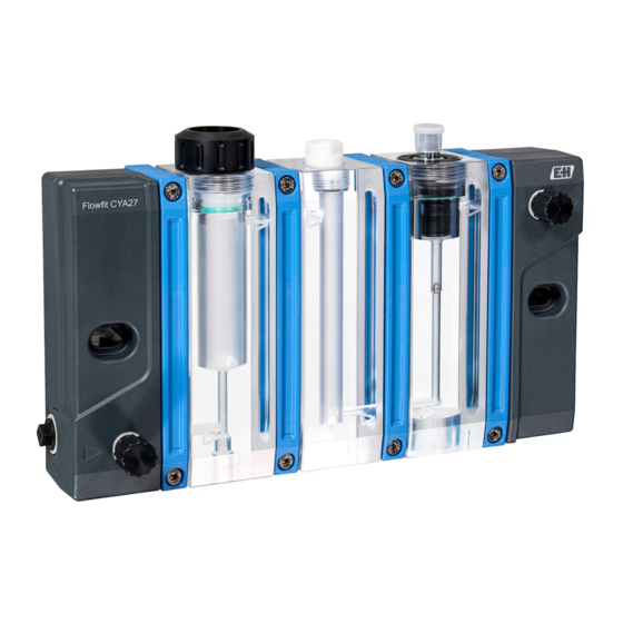
- Page 1 Products Solutions Services BA02059C/07/EN/02.21 71511599 2021-01-07 Operating Instructions Flowfit CYA27 Modular flow assembly for multiparameter measurements...
-
Page 3: Table Of Contents
Flowfit CYA27 Table of contents Table of contents About this document ....4 Repair ......41 Warnings . -
Page 4: About This Document
About this document Flowfit CYA27 About this document Warnings Structure of information Meaning This symbol alerts you to a dangerous situation. DANGER Failure to avoid the dangerous situation will result in a fatal or serious Causes (/consequences) injury. If necessary, Consequences of non-compliance (if applicable) ‣... -
Page 5: Basic Safety Instructions
Flowfit CYA27 Basic safety instructions Basic safety instructions Requirements for personnel • Installation, commissioning, operation and maintenance of the measuring system may be carried out only by specially trained technical personnel. • The technical personnel must be authorized by the plant operator to carry out the specified activities. -
Page 6: Operational Safety
Basic safety instructions Flowfit CYA27 Operational safety Before commissioning the entire measuring point: 1. Verify that all connections are correct. 2. Ensure that electrical cables and hose connections are undamaged. 3. Do not operate damaged products, and protect them against unintentional operation. -
Page 7: Product Description
Product description Product design The Flowfit CYA27 is a modular assembly designed for operating sensors for liquid analysis with continuous flow of medium. The sensors are placed in specially adapted modules. Due to its modular design, the assembly is flexible in terms of the number and type of sensor slots. - Page 8 Product description Flowfit CYA27 Module for disinfection sensors • Medium flows to sensor from below • Sensor slot for 25 mm sensors • Sensor secured via pressure screw M35x2 • Sensors: CCS5x(D) • Flow options • 5 l/h (1.1 gal/h) •...
- Page 9 Flowfit CYA27 Product description Module for conductivity sensor CLS82D • Medium flows to sensor from below • Adapter for sensor CLS82D (12 mm sensor with Pg 13.5 thread in 120 mm length) • Optional function: sampling valve (not shown here)
-
Page 10: Incoming Acceptance And Product
Incoming acceptance and product identification Flowfit CYA27 Incoming acceptance and product identification Incoming acceptance 1. Verify that the packaging is undamaged. Notify the supplier of any damage to the packaging. Keep the damaged packaging until the issue has been resolved. -
Page 11: Scope Of Delivery
5. Click on the product image in the popup window. A new window (Device Viewer) opens. All of the information relating to your device is displayed in this window as well as the product documentation. Manufacturer's address Endress+Hauser Conducta GmbH+Co. KG Dieselstraße 24 D-70839 Gerlingen Scope of delivery The scope of delivery comprises: •... -
Page 12: Installation
Installation Flowfit CYA27 Installation Installation conditions 5.1.1 Orientation The assembly is designed for mounting on panels, walls, level surfaces, masts or railings. The only permitted orientation of the assembly is horizontal, → 15. The prescribed orientation of the assembly may limit the installation of certain sensors. - Page 13 Flowfit CYA27 Installation 5.1.3 Dimensions Flowfit CYA27 Flowfit CYA27 Flowfit CYA27 285 (11.22) 345 (13.58) 225 (8.86) 60 (2.36) Flowfit CYA27 Flowfit CYA27 Flowfit CYA27 165 (6.50) 165 (6.50) A0042901 1 Dimensions. Engineering unit: mm (in) Disinfection, pH and flow rate indication version with sampling valve, status indication light and flow switch...
- Page 14 Installation Flowfit CYA27 A0043194 2 Mounting distance. Engineering unit: mm (in) The mounting distance required to remove the sensor is 175 mm (6.9 in). Endress+Hauser...
-
Page 15: Mounting The Assembly
A complete measuring system may contain up to six different sensors and consists, for example, of the following: • Flowfit CYA27 flow assembly • At least one sensor, e.g. CCS51D for measuring free chlorine • At least one measuring cable, e.g. CYK10 •... - Page 16 Installation Flowfit CYA27 Number of modules Spacing between drill 120 (4.73) 180 (7.09) 240 (9.45) holes mm (in) The mounting materials required to secure the device to the wall are not supplied. 1. Provide the mounting materials to secure the device to the wall (screws, wall plugs) onsite.
- Page 17 Flowfit CYA27 Installation A0043207 A0043208 6 2 securing clips for 1 to 5 modules 7 3 securing clips for 6 modules With six modules, three securing clips are required for increased stability. 1. Position the assembly in the center of the wall bracket.
-
Page 18: Mounting Assembly In The Process
Installation Flowfit CYA27 Mounting assembly in the process 5.3.1 General installation instructions CAUTION Risk of injury from high pressure, high temperature or chemical hazards if process medium escapes. ‣ Wear protective gloves, protective goggles and protective clothing. ‣ Install the assembly only in vessels or pipes that have cooled down, are empty and unpressurized and have been rinsed. - Page 19 Flowfit CYA27 Installation 5.3.3 Open outlet With this type of installation, the assembly is located in a branch pipe that branches off a main line and terminates in an open outlet→ 8, 19. Ideally, the open outlet is unpressurized or without counterpressure.
- Page 20 Installation Flowfit CYA27 5.3.4 Bypass with return The counterpressure p2 is the definitive counterpressure for the assembly or sensors and must not under any circumstances exceed the permitted pressure specification of the assembly or sensors. To achieve flow through the assembly with a bypass, pressure p1 must be higher than pressure p2.
- Page 21 Flowfit CYA27 Installation 5.3.5 Automatic cleaning of the assembly via the dosing module For the metered addition of a cleaning agent or an acid (to acidify a medium), the following is required at a minimum: • an assembly with dosing module, •...
-
Page 22: Flow Switch And Status Indication Light (Optional)
Installation Flowfit CYA27 Flow switch and status indication light (optional) WARNING Device is live! Incorrect connection may result in injury or death! ‣ The electrical connection may be performed only by an electrical technician. ‣ The electrical technician must have read and understood these Operating Instructions and must follow the instructions contained therein. - Page 23 Flowfit CYA27 Installation A0043505 BASE-E or BASE2-E module DIO module (included in the scope of delivery of the CM44x or can be ordered separately) Flow switch cable Flow switch Status indication light cable Distributor terminal (included as standard in the CM44x) The flow switch cable and the status indication light cable are identical.
- Page 24 Installation Flowfit CYA27 Connecting cable Green (GN) DIO module, port 1, terminal 48 Distributor terminal (3) Distributor terminal (4) not connected 5.4.2 Settings on the CM44x Activating the binary input of the flow switch 1. Go to Menu/Setup/Inputs/Binary input x:1 and enable Binary input.
-
Page 25: Installing Sensor In Assembly
2. The assembly is supplied to the customer with a dummy plug inserted in the assembly: remove dummy plug and O-ring (1) from the assembly. 3. Slide the sensor with the adapter for Flowfit CYA27 into the opening in the assembly. 4. Screw union nut onto assembly on block. - Page 26 Installation Flowfit CYA27 5.5.2 pH, ORP or oxygen sensor A0043537 1. The assembly is supplied to the customer with a dummy screw mounted in the assembly. 2. Remove dummy screw, thrust collar and O-ring (1) from the assembly using a hexagon wrench AF17.
-
Page 27: Connecting Optional Accessories
Flowfit CYA27 Installation 1. The assembly is supplied to the customer with a dummy screw mounted in the assembly. 2. Remove dummy screw, thrust collar and O-ring (1) from the assembly using a hexagon wrench AF17. 3. Slide the sensor into the adapter of the assembly. -
Page 28: Commissioning
Commissioning Flowfit CYA27 Commissioning CAUTION Risk of injury from high pressure, high temperature or chemical hazards if process medium escapes. ‣ Before subjecting the assembly to the process pressure, verify that all connections are sealed. ‣ Wear personal protective equipment consisting of protective gloves, goggles and protective clothing. -
Page 29: Operation
Flowfit CYA27 Operation Operation CAUTION Compressed media Risk of injury from high pressure, high temperature or chemical hazards if process medium escapes. ‣ Wear personal protective equipment consisting of protective gloves, goggles and protective clothing. Adapting the measuring device to the process conditions 7.1.1... -
Page 30: Sampling
Operation Flowfit CYA27 Sampling Depending on the module selected, the assembly can be optionally fitted with a valve for sampling. The sample, for example for a DPD test for sensor calibration, is taken as follows: 1. Carefully open the sampling valve and rinse for a few seconds. - Page 31 Flowfit CYA27 Operation To avoid this, the sensor values at the transmitter can be set to HOLD for the duration of sampling. In this case, sampling is performed as follows: 1. Set the sensor measured values on the transmitter to HOLD.
-
Page 32: Diagnostics And Troubleshooting
Diagnostics and troubleshooting Flowfit CYA27 Diagnostics and troubleshooting General troubleshooting Faults at the measuring point can affect not only the assembly but also the sensors and transmitters used. For this reason, the respective Operating Instructions of the sensors and transmitters must also be observed for diagnostics and troubleshooting. -
Page 33: Maintenance
Flowfit CYA27 Maintenance Maintenance CAUTION Danger resulting from improper maintenance ‣ Maintenance work on the assembly that compromises pressure safety must be performed only by authorized specialist staff. ‣ The valve must comply with the original technical specifications following each maintenance activity. -
Page 34: Maintenance Tasks
Maintenance Flowfit CYA27 Maintenance tasks 9.2.1 Decommissioning CAUTION Compressed media Risk of injury from high pressure, high temperature or chemical hazards if process medium escapes. ‣ Wear personal protective equipment consisting of protective gloves, goggles and protective clothing. ‣ Perform maintenance or repair work on the assembly only when it is depressurized, has cooled down and has been rinsed. - Page 35 Flowfit CYA27 Maintenance 2. Open the sampling valve. The medium is discharged via the outlet line. At a prepared workstation (e.g. with collection basin or drain): 1. Disconnect the assembly from the process connection. 2. Remove the assembly from the wall bracket.
- Page 36 Maintenance Flowfit CYA27 The following methods and cleaning agents are recommended: 1. Remove light dirt and fouling using a cloth moistened with suitable cleaning solutions. 2. Remove heavy soiling using a soft brush and a suitable cleaning agent. 3. For very persistent dirt, soak the parts in a cleaning solution. Then clean the parts with a brush.
- Page 37 Flowfit CYA27 Maintenance 6. Put the measuring point into operation (→ 28), paying particular attention to leak-tightness. For detailed information on "Cleaning the sensor", see Operating Instructions for sensor. 9.2.5 Calibrating or replacing the sensors For detailed information on "Calibrating the sensor", see Operating Instructions for sensor.
- Page 38 Maintenance Flowfit CYA27 2. Rinse and drain the assembly as required (→ 34). 3. Disconnect the assembly from the process. 4. Remove the assembly from the wall installation (→ 39). 5. Using the clips, separate the assembly into the modules(→ 37).
-
Page 39: Disassembly (For Conversion, Cleaning Etc.)
Flowfit CYA27 Maintenance Gasket seal with bore hole A0044056 A0044058 A0044059 A0044057 A0044060 Gasket seal with channel A0044061 A0044063 A0044064 A0044062 A0044065 The flow function of the assembly is dependent on the correct use of seals that are suitable for the adjacent modules in question. An incorrectly inserted seal may lead to a flow blockage. - Page 40 Maintenance Flowfit CYA27 Flowfit CYA27 A0043717 Detents 1. Keep detents pressed down. 2. Slide the assembly upwards and out of the holder. Endress+Hauser...
-
Page 41: Repair
Flowfit CYA27 Repair Repair CAUTION Incorrect repair Danger due to damage to the device! ‣ Any damage to the assembly that compromises pressure safety must be repaired only by authorized and qualified personnel. ‣ The assembly must comply with the original technical specifications following repair work. -
Page 42: Return
The product must be returned if repairs or a factory calibration are required, or if the wrong product was ordered or delivered. As an ISO-certified company and also due to legal regulations, Endress+Hauser is obliged to follow certain procedures when handling any returned products that have been in contact with medium. -
Page 43: Accessories
Flowfit CYA27 Accessories Accessories The following are the most important accessories available at the time this documentation was issued. ‣ For accessories not listed here, please contact your Service or Sales Center. 11.1 Device-specific accessories 11.1.1 Disinfection sensors CCS51D • Sensor for measuring free chlorine •... - Page 44 Accessories Flowfit CYA27 11.1.3 ORP sensors Orbisint CPS12D / CPS12 • ORP sensor for process technology • Product Configurator on the product page: www.endress.com/cps12d www.endress.com/cps12 Technical Information TI00367C 11.1.4 pH and ORP combined sensors Memosens CPS16D • Combined pH/ORP sensor for process technology •...
-
Page 45: Technical Data
Flowfit CYA27 Technical data Technical data 12.1 Power supply Cable specification Cable accessories 10 m (32.8 ft), M12 socket straight, 5-pin version Cable accessories Ex (US) Cl.1 Div.2 cable, 10 m (32.8 ft), M12 socket straight, 4-pin version 12.2 Performance characteristics Reference operating 20 °C (68 °F) -
Page 46: Process
Technical data Flowfit CYA27 12.4 Process Process temperature range 0 to 60 °C (32 to 140 °F), non-freezing Process pressure range 0 to 4 bar (0 to 58 psi) relative Pressure/temperature p [psi] p [bar] ratings 70 T[°C] T[°F] A0044367 ... -
Page 47: Mechanical Construction
Flowfit CYA27 Technical data 12.5 Mechanical construction → 13 Weight Depends on the configuration: • 1 module: 0.9 kg (1.98 lb) • 2 modules: 1.5 kg (3.31 lb) • 3 modules: 2.1 kg (4.63 lb) • 4 modules: 2.7 kg (5.95 lb) •... -
Page 48: Index
Index Flowfit CYA27 Index Accessories ....... . 43 Technical data ......45 Approvals . - Page 52 *71511599* 71511599 www.addresses.endress.com...