Table of Contents
Advertisement
Quick Links
Important Information
Copyright
This publication, including all photographs, illustrations and software, is
protected under international copyright laws, with all rights reserved.
Neither this manual, nor any of the material contained herein, may be
reproduced without the express written consent of the manufacturer.
Disclaimer
The information in this document is subject to change without notice. The
manufacturer makes no representations or warranties with respect to the
contents hereof and specifically disclaims any implied warranties of
merchantability or fitness for any particular purpose. Further, the
manufacturer reserves the right to revise this publication and to make
changes from time to time in the content hereof without obligation of the
manufacturer to notify any person of such revision or changes.
Trademark Recognition
Microsoft, MS-DOS and Windows are registered trademarks of Microsoft
Corp.
MMX, Pentium, Pentium-II, Pentium-III, Celeron are registered
trademarks of Intel Corporation.
VGA, OS/2, PS/2 are registered trademarks of International Business
Machines.
AMD, K5, K6 are registered trademarks of Advanced Micro Devices Inc.
Cyrix, M1 are registered trademarks of Cyrix Corporation.
Other product names used in this manual are the properties of their
respective owners and are acknowledged.
Version 1.0
For marketing inquiries:
For technical support:
Website:
mkt_tpe@ecs.com.tw
support_tpe@ecs.com.tw
http://www.ecs.com.tw
Advertisement
Table of Contents

Related Manuals for ECS P6VAP-Me


Summary of Contents for ECS P6VAP-Me
- Page 1 AMD, K5, K6 are registered trademarks of Advanced Micro Devices Inc. Cyrix, M1 are registered trademarks of Cyrix Corporation. Other product names used in this manual are the properties of their respective owners and are acknowledged. Version 1.0 For marketing inquiries: mkt_tpe@ecs.com.tw For technical support: support_tpe@ecs.com.tw Website: http://www.ecs.com.tw...
- Page 2 Safety Compliance Federal Communications Commission (FCC) This equipment has been tested and found to comply with the limits for a Class B digital device, pursuant to Part 15 of the FCC Rules. These limits are designed to provide reasonable protection against harmful interference in a residential installation.
-
Page 3: Table Of Contents
Contents Chapter 1: Introduction..........1 Welcome...............1 About the Manual............2 Checklist...............3 Standard Items--------------------------------------------------3 Optional Items---------------------------------------------------3 Recommendations............3 Features...............4 Chapter 2: Installation..........8 Quick Installation Table..........8 Quick Jumper Setting Reference........9 Before You Begin............13 Static Electricity-------------------------------------------------13 Choosing a Case------------------------------------------------14 How to Set Jumpers--------------------------------------------14 Preparing the Mainboard..........16 Mainboard Guide------------------------------------------------16 I/O Ports Side View---------------------------------------------18 Check the Jumper Settings----------------------------------19... - Page 4 Running the Support CD-ROM........70 Utility Folder Installation Notes........70 CMI8X38 Folder Installation Notes.......71 Audio Software--------------------------------------------------71 Modem Driver and Software---------------------------------72 Peripheral Folder Installation Notes......72 VIA Folder Installation Notes........72 GL520SM Folder Installation Notes......73 Mainboard (P6VAP-Me) Installation Notes....73 Appendix 1: Quick Jumper Setting Reference..74...
-
Page 5: Chapter 1: Introduction
Chapter 1: Introduction Chapter 1: Introduction Welcome Congratulations on purchasing the P6VAP-Me mainboard. This mainboard features the latest VIA VT82C694X/596B chipset. The mainboard features a FC-PGA (Plastic Pin Grid Array) PGA370 processor socket. This feature means that you can install the mainboard with a FC-PGA Celeron or Cyrix Joshua processor. -
Page 6: About The Manual
This chapter contains the following information: About the Manual explains how the information in this manual is organized Checklist comprises a list of the standard and optional components that are shipped with this mainboard Recommendations lists some Do’s and Don’ts from the manufacturer to help ensure reliability and performance from this product ... -
Page 7: Checklist
If any item is missing or appears damaged, please contact the vendor of your mainboard package. Standard Items 1 x P6VAP-Me Mainboard 1 x Cable/Bracket Pack Diskette drive ribbon cable DMA 66 IDE drive ribbon cable ... -
Page 8: Features
Features The key features of this mainboard are the advanced VIA VT82C694XA/ 596B chipset, and the FC-PGA processor support so that you can install a wide range of Intel Celeron or Cyrix Joshua processors. You can use this board to develop a low-cost value system, with very comprehensive features. - Page 9 The VIA chipset on this board supports an asynchronous memory bus architecture, and provides option of 66/100, 100/66, 100/133 or 133/100 MHz CPU and memory bus combinations. Optimized Chipset This board uses the VIA VT82C694X/596B chipset. The VT82C694X forms the north bridge and supports system buses of 66, 100 and 133 MHz.
- Page 10 Optional Built-in Communications The mainboard has an integrated fax/modem connector. As an option, you can purchase a fax/modem extension bracket which connects the line and telephone RJII sockets to the board. The fax/modem supports the V.90 protocol that allows transmissions at up to 56Kbps and is fully compatible with earlier transmission and error correction standards.
- Page 11 Programmable Firmware The mainboard includes Award BIOS that allows BIOS setting of CPU parameters. The fully programmable firmware enhances the system features and allows users to set power management, CPU and memory timing, LAN and modem wake-up alarms, and so on. The firmware can also be used to set parameters for different processor clock speeds so that you don’t need to change mainboard jumpers and switches.
-
Page 12: Chapter 2: Installation
Chapter 2: Installation Chapter 2: Installation Quick Installation Table This chapter explains how to successfully install the mainboard into a computer case and build a working system. The installation procedure is as follows: Quick Jumper Provides a quick reference for the jumper Setting Reference settings on this mainboard. -
Page 13: Quick Jumper Setting Reference
Quick Jumper Setting Reference If you are familiar with most of the material in this chapter, you can begin preparing the mainboard for installation by using this quick reference to begin setting the jumpers. A detailed description of the jumper setting appears later in this chapter. - Page 14 JP5: Supend-to-RAM jumper Use this 3-pin jumper to enable the Suspend-to-RAM function. Function Jumper Cap Enable Suspend-to-RAM Short pins 1-2 1 2 3 Disable Suspend-to-RAM Short pins 2-3 JP8: Set System Bus Frequency to 133 MHz Use this 3-pin jumper to set the system bus frequency. In the normal setting, the system automatically selects the correct frequency according to the kind of processor installed.
- Page 15 JP12: Flash BIOS jumper Use this 3-pin jumper to enable or disable Flash BIOS protection. If enabled, the existing BIOS cannot be flashed with another version. Function Jumper Cap JP12 Enable Flash BIOS Short pins 1-2 1 2 3 Disable Flash BIOS Short pins 2-3 VID: Set CPU core voltage jumpers 1 2 3...
- Page 16 Short Pin Settings Volt. VID1 VID2 VID3 VID4 VID5 2.7V 2.6V 2.5V 2.4V 2.3V 2.2V 2.1V *Auto: When all 1-2 pins are shorted, the core voltage will automatically be determined. BF: Set system bus multiplier ratio jumpers 1 2 3 Use this 3 x 4-pin jumper set to manually set the system bus multiplier ratio.
-
Page 17: Before You Begin
Before You Begin Before you begin to install your P6VAP-Me mainboard, take some precautions to ensure that you avoid the possibility of damage to the product from static electricity. Ensure too that you are installing the mainboard into a suitable case. -
Page 18: Choosing A Case
Some features on the mainboard are implemented by cabling connectors on the board to indicators and switches on the system case. Ensure that your case supports all the features required. The P6VAP-Me mainboard can support one or two floppy diskette drives and four enhanced IDE drives. - Page 19 This illustration shows a 3-pin jumper. The jumper cap is placed on pins 2 and 3, so this jumper setting is SHORT PINS 2-3. This illustration shows the same 3-pin jumper. The jumper cap is placed on pins 1 and 2, so this jumper setting is SHORT PINS 1-2.
-
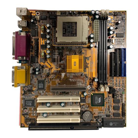
Page 20: Preparing The Mainboard
Preparing the Mainboard Mainboard Guide Use the following illustration and key to identify the components on your mainboard. - Page 21 Key to Mainboard Components Component Description SOCKET-370 Socket for Intel FC-PGA Celeron or Cyrix Joshua processor DIMM1, DIMM2 Slots for 168-pin memory modules IDE1, IDE2 Primary and secondary IDE channels FDD1 Connector for floppy disk drives AGP1 Slot for AGP graphics adapter PCI 1, 2, 3 3 x 32-bit PCI expansion slot ISA1...
-
Page 22: I/O Ports Side View
*LED1 This red indicator turns on if your system is suspended to RAM. In a suspend to RAM, the system turns off most of the power-consuming components except for the 3.3V required to refresh the memory. If LED1 is turned on, it warns you that the computer is still active and you should not carry out any work on the mainboard. -
Page 23: Check The Jumper Settings
Check the Jumper Settings Check all the mainboard jumpers to ensure that the board is configured correctly. JP11 JP10 JP12 JP1: Clear CMOS Memory Jumper This jumper lets you erase the system setup settings that are stored in CMOS memory. You might need to erase this data if incorrect settings are preventing your system from operating. - Page 24 JP2: Keyboard Power On Jumper This jumper lets you use a typed-in password as a power switch to turn your system on. If you enable this property, you need to define the password or the hot keys using the setup utility. See Chapter 3 for more information.
- Page 25 JP5: Suspend-to-RAM Jumper Use this 3-pin jumper to enable the Suspend-to-RAM feature. In a Suspend-to-RAM condition, the contents of the system’s memory is held intact, while practically all other components are turned off completely or slowed down to reduce power consumption. Function Jumper Cap Enable Suspend-to-RAM...
- Page 26 JP10: Automatic (BIOS) or Manual configuration Use this 2-pin jumper to automatically (BIOS) or manually set the CPU core voltage and system bus multiplier ratio. When set to manual configuration, use the VID and BF jumpers to define proper configuration. It is recommended that you set this jumper to automatic configuration.
- Page 27 Short Pin Settings Volt. VID1 VID2 VID3 VID4 VID5 1.45V 1.40V 1.35V 1.30V 3.5V 3.4V 3.3V 3.2V 3.1V 3.0V 2.9V 2.8V 2.7V 2.6V 2.5V 2.4V 2.3V 2.2V 2.1V *Auto: When all 1-2 pins are shorted, the core voltage will automatically be determined.
- Page 28 Short Pin Settings Ratio Auto* Res. *Auto: When all 1-2 pins are shorted, the system bus multiplier ratio will automatically be determined.
-
Page 29: Install The Mainboard In The Case
Install the Mainboard in the Case The mainboard is drilled with a series of holes. Most system cases have mounting brackets installed in the case which correspond to the holes in the mainboard. You can secure the mainboard in the system case by placing the mainboard over the mounting brackets and driving screws through the mainboard into the mounting brackets. -
Page 30: Connecting Power, Chassis Fan, And Panel
Connecting Power, Chassis Fan, and Panel After you have installed the mainboard into the system case, connect the power cable from the case power supply unit to the mainboard power connector ATX1. Connect the chassis (if your case has them) to the 12V power supply connector PWRFAN1 on the mainboard. - Page 31 Power Connector Locate the power cable from the case power supply unit and plug it into the ATX1 power connector. Chassis Fan If your case has a cooling fan installed, plug the cable from the fan into the mainboard fan power supply PWRFAN1. CLED1 Use the CLED1 connector to connect a dual color LCD to the mainboard.
-
Page 32: Install Other Hardware
Install Other Hardware Start installing the essential hardware required to get your system started. Install the Processor This mainboard has a Socket-370 processor socket. To choose a processor, you need to consider the performance requirements of the system and also the price of the processor. Performance is based on the processor design, the clock speed and system bus frequency of the processor, and the quantity of internal cache memory and external cache memory. -
Page 33: Installing A Socket-370 Processor
Installing a Socket-370 Processor If you have decided to install the mainboard with a FC-PGA Celeron processor, follow the steps below. Locate the Socket-370 and CPUFAN1 1. On the mainboard, locate the socket-370 and CPUFAN1. 2. On the socket-370, pull the locking lever away from the socket to unhook it and then raise the locking lever to the upright position. - Page 34 The mainboard must be configured to deliver the correct clock speed and the correct system bus for the kind of processor that you have installed. You can do this by either using the system setup utility, or manually, by setting the correct jumper settings on the board. The first time you start the system, immediately enter the setup system and make the appropriate settings.
-
Page 35: Install The Memory Modules
Install the Memory Modules For this mainboard, you must use 168-pin 3.3V non-buffered Dual In-line Memory Modules (DIMMs). The memory chips must be standard or registered SDRAM (Synchronous Dynamic Random Access Memory). The memory bus can run at 100 MHz or 133 MHz. If your processor operates over a 133 MHz system bus, you must install PC-133 memory that also operates over a 133 MHz bus. -
Page 36: Install A Hard Disk Drive And Cd-Rom
Install a Hard Disk Drive and CD-ROM This section describes how to install IDE devices such as a hard disk drive and a CD-ROM drive. Note: Ribbon cable connectors are usually keyed so that they can only be installed correctly on the device connector. If the connector is not keyed make sure that you match the pin-1 side of the cable connector with the pin-1 side of the device connector. - Page 37 Installing a Hard Disk Drive 1. Install the hard disk drive into the drive cage in your system case. 2. Plug the IDE cable into the primary IDE channel on the mainboard IDE1. 3. Plug one of the connectors on the IDE cable into the IDE connector on the back edge of the hard disk drive.
- Page 38 Installing a CD-ROM Drive 1. Install the CD-ROM drive into the drive cage in your system case. 2. Plug the IDE cable into the primary IDE channel on the mainboard IDE1. 3. Plug one of the connectors on the IDE cable into the IDE connector on the back edge of the CD-ROM drive.
-
Page 39: Installing A Floppy Diskette Drive
Installing a Floppy Diskette Drive The mainboard has a floppy diskette drive interface and it ships with a diskette drive ribbon cable that supports one or two floppy diskette drives. You can install a 5.25” drive or a 3.5” drive with various capacities. -
Page 40: Using The Expansion Slots
Using the Expansion Slots This mainboard has several expansion slots. You can install add-in cards into these slots to add new features to your system. In order to get your system started, you must install an add-in graphics adapter. The mainboard has three kinds of expansion slots. - Page 41 3. In the system case, remove the blanking plate from the slot in the system case that corresponds to the expansion slot that you are going to use. 4. Position the edge connector of the add-in card over the expansion slot.
-
Page 42: Add-In Card Options
Add-in Card Options The mainboard has some features that can be used by some types of add-in cards. WOL1: Wake on LAN If you have installed a network adapter (LAN adapter), you can use the cable provided with the card to plug into the WOL1 connector on the mainboard. -
Page 43: Install Options And Extension Brackets
Install Options and Extension Brackets This mainboard has a number of special connectors that allow you to add optional features to your system. You can install any of the following items: Fax/modem card option Infrared port 24-bit digital audio extension bracket (SPDIF) ... - Page 44 Line and Tel Fax/modem RJ11 sockets card fax/modem connector Infrared Port This option can be purchased from third-party vendors. SIR1 1. If you are installing an optional serial infrared port, connect the cable from the optional IR port to the SIR1 connector on the mainboard. 2.
- Page 45 Digital Audio Extension Bracket You can purchase an optional 24-bit digital audio extension bracket from a third-party vendor. You can use the audio RCA jacks to connect to digital audio devices. If your CD-ROM/DVD drive has digital audio output, you can connect it to the input pins of the SPDIF connector. On the mainboard, locate the digital audio connector SPDIF1.
- Page 46 Make the External Connections After you have installed the mainboard, make the connections to the external ports. 1. KBMPS2 is a stack of two PS/2 mini-DIN ports. The upper port can be used by a PS/2 mouse or pointing device. The lower port can be used by a PS/2 keyboard.
-
Page 47: External Connector Color Coding
External Connector Color Coding To help identify the external connectors, many connectors now use standard colors as shown in the table below. Connector Color Analog VGA Blue Audio line in Light blue Audio line out Lime Digital monitor / flat panel White IEEE 1394 Grey... -
Page 48: Chapter 3: Setup
Chapter 3: Setup Chapter 3: Setup About the Setup Utility This chapter explains how to use and modify the BIOS setup utility that is stored on the mainboard. The setup utility stores data about the mainboard components and the configuration of devices that are connected to it. - Page 49 Some options (marked with a triangle) lead to tables of items that usually have a value on the right side. The value of the first item is highlighted, and you can use the cursor arrow keys to select any of the other values in the table of items.
-
Page 50: How To Flash A New Bios
How to Flash a New BIOS You can install an updated BIOS for this motherboard that you can download from the manufacturer’s website. New BIOS may provide support for new peripherals, improvements in performance or fixes to address known bugs. Install a new BIOS as follows: 1. -
Page 51: Standard Cmos Features Option
9. In the opening dialog box, type in the filename of the new BIOS and follow the onscreen directions to flash the new BIOS to the motherboard. 10. When the installation is complete, remove the floppy diskette from the diskette drive and restart your computer. If your mainboard has a Flash BIOS jumper, don’t forget to reset the jumper to protect the newly installed BIOS from being overwritten. - Page 52 IDE HDD Auto-Detection Press Enter while this item is highlighted if you want the setup utility to automatically detect and configure a hard disk drive on the IDE channel. IDE Primary/Secondary Master/Slave If you leave this item at Auto, the system will automatically detect and configure any IDE devices it finds.
-
Page 53: Advanced Bios Features Setup Option
Halt On Default: All Errors This item defines the operation of the system POST (Power On Self Test) routine. You can use this item to select which kind of errors in the POST are sufficient to halt the system. Base Memory, Extended Memory, Total Memory These items are automatically detected by the system at start up time. - Page 54 CPU Internal Cache Default: Enabled All the processors that can be installed in this mainboard use internal (level 1) cache memory to improve performance. Leave this item at the default value Enabled for better performance. External Cache Default: Enabled Most processors that can be installed in this system use external (L2) cache memory to improve performance.
-
Page 55: Advanced Chipset Features Option
Typematic Rate Setting Default: Disabled If this item is enabled, you can use the following two items to set the typematic rate and the typematic delay settings for your keyboard. Typematic Rate (Chars/Sec) Default: 6 If the item Typematic Rate Setting is enabled, you can use this item to define how many characters per second are generated by a held-down key. - Page 56 Bank 0/1 DRAM Timing Default: SDRAM 10ns Bank 2/3 DRAM Timing Default: SDRAM 10ns This item allows you to set the speed of the memory used in the DIMM slots. SDRAM Cycle Length Default: 3 This item controls how often the data in memory will be accessed. You can set the value to 2 or 3 clock cycles.
- Page 57 AGP Aperture Size (MB) Default: 64 MB This item defines the size of the aperture if you use an AGP graphics adapter. It refers to a section of the PCI memory address range used for graphics memory. We recommend that you leave this item at the default value. AGP 4X Mode Default: Enabled This item allows you to improve video performance by quadrupling the speed of...
-
Page 58: Integrated Peripherals Option
Integrated Peripherals Option This option displays a list of items which defines the operation of some peripheral items on the system’s input/output ports. OnChip IDE Channel0 Default: Enabled OnChip IDE Channel1 Default: Enabled Use these items to enable or disable the Primary and Secondary PCI IDE channels that are integrated on this mainboard. - Page 59 Init Display First Default: PCI Slot Use this item to define if your graphics adapter is installed in one of the PCI slots or select Onboard if you have a graphics system integrated on the mainboard. Onboard PCI Audio Default: Enabled Use this item to enable the onboard audio features.
-
Page 60: Power Management Setup Option
settings (usually IrDA or FIR). These settings will disable the external COM2 serial port connector and assign the resources to the infrared device. If you have selected an IR mode, use the following item UR2 Duplex Mode to define if the IR port is full duplex or half duplex. - Page 61 Wake Up Calls If the system is suspended, or has been powered down by software, it can be resumed by a wake up call that is generated by incoming traffic to a modem, a LAN card, a PCI card, or a fixed alarm on the system realtime clock.
- Page 62 Power Management Default: User Define This item acts like a master switch for the power-saving modes and hard disk timeouts. If this item is set to Max Saving, power-saving modes occur after a short timeout. If this item is set to Min Saving, power-saving modes occur after a longer timeout.
- Page 63 Video Off Method Default: DPMS Support This item defines how the video is powered down to save power. As a default, this is set to DPMS (display power management software). MODEM Use IRQ Default: 3 If you want an incoming call on a modem to automatically resume the system from a power-saving mode, use this item to specify the interrupt request line (IRQ) that is used by the modem.
- Page 64 HDD & FDD Default: ON When this item is enabled, the system will restart the power-saving timeout counters when any activity is detected on the floppy diskette drives or on the IDE drive channels. DMA/Master Default: OFF When this item is enabled, the system will restart the power-saving timeout counters when any activity is detected on the DMA (Direct Memory Access) channels.
- Page 65 When these item are enabled, the system will restart the timeout counters when any activity is detected on the selected Interrupt request lines. When the Primary INTR item is set to OFF, then the interrupts have no effect on system power management Press Esc to close the the IRQ Activity Monitoring sub-menu and return to the Wake Up Events page.
-
Page 66: Pnp/Pci Configuration Option
PNP/PCI Configuration Option This option displays a table of items that configures how PNP (Plug and Play) and PCI expansion cards operate in your system. PNP OS Installed Default: No If you have installed a Plug and Play operating system, such as Windows 95 or 98, you can change this item to Yes. -
Page 67: Pci Health Status Option
PCI/VGA Palette Snoop Default: Disabled This item is designed to overcome some problems that can be caused by some non-standard VGA cards. This board includes a built-in VGA system that does not require palette snooping so you must leave this item disabled. Assign IRQ For VGA Default: Enabled Assign IRQ For USB... -
Page 68: Frequency / Voltage Control Option
Frequency / Voltage Control Option This item allows you to set the clock speed and system bus for your system. The clock speed and system bus are determined by the kind of processor you have installed in your system. Auto Detect DIMM/PCI Clk Default: Disabled When this item is enabled, the BIOS will disable the clock generator signal for unused DIMM and PCI slots, in order to reduce EMI (electromagnetic... -
Page 69: Load Fail-Safe Defaults Option
CPU clock failed reset Default: Disabled If this item is enabled, and your system crashes three times because you have overclocked the processor, this item will automatically adjust the speed of the processor to the system bus speed multiplied by two. CPU Voltage Default: Auto The onboard hardware monitor is able to automatically detect the voltage output... -
Page 70: Save And Exit Setup Option
3. If you are installing a new password, carefully type in the password. You cannot use more than 8 characters or numbers. The password will differentiate between upper case and lower characters. Press Enter after you have typed in the password. If you are deleting a password that is already installed just press Enter when the password dialog box appears. -
Page 71: Chapter 4: Software
The software for this mainboard is stored in the P6VAP-Me folder. Note: Never try to install software from a folder that is not specified for use with your mainboard. - Page 72 95/98 WinNT: This folder has hardware monitoring software for Windows NT ver. 4.0 P6VAP-Me Folder AUDIO, MODEM: These folders are empty. A readme file directs you to an alternate location with the required software. Note: Some folders are subdivided into different operating systems such as DOS, Windows 95, Windows NT, and so on.
-
Page 73: Running The Support Cd-Rom
Running the Support CD-ROM 1. Place the disk in your CD-ROM drive. If you are running Windows with Autoplay enabled, the opening screen of the CD appears automatically. Click on READ ME to read the latest instructions. 2. Click on the item BROWSE THE CD TITLE. This uses Windows Explorer to show the contents of the support CD. -
Page 74: Cmi8X38 Folder Installation Notes
GAMUT The Gamut audio rack software for the built-in sound system is provided for different languages. Log on to the appropriate directory for your language, then run SETUP to install the application software. MediaRing Talk To install the MediaRing Talk voice modem software for the built-in modem, run MRTALK99-SETUP. -
Page 75: Modem Driver And Software
5. Press the "Add..." button. 6. Select item "Unlisted or Updated Driver" in the "List of Drivers" list box. 7. Specify the path to the PCI audio NT drivers. 8. Select "C-Media PCI Device" and press the "OK" button. 9. Choose proper I/O or the "OK" button for the default setting. 10. -
Page 76: Gl520Sm Folder Installation Notes
SETUP.EXE. Follow the screen prompts to complete the installation. Mainboard (P6VAP-Me) Installation Notes All of the sub-folders in this folder are empty, with a short README file giving directions to alternate folders for the appropriate software. -
Page 77: Appendix 1: Quick Jumper Setting Reference
Appendix 1: Quick Jumper Setting Reference JP1: Clear CMOS memory jumper Use this 3-pin jumper to clear all the current data stored in the CMOS memory. Function Jumper Cap Normal operation Short pins 1-2 1 2 3 Clear CMOS Short pins 2-3 JP2: Keyboard power on jumper Use this 3-pin jumper to enable keyboard power on with hot keys or password. - Page 78 JP5: Supend-to-RAM jumper Use this 3-pin jumper to enable the Suspend-to-RAM function. Function Jumper Cap Enable Suspend-to-RAM Short pins 1-2 Disable Suspend-to-RAM Short pins 2-3 1 2 3 JP8: Set System Bus Frequency to 133 MHz Use this 3-pin jumper to set the system bus frequency. In the normal setting, the system automatically selects the correct frequency according to the kind of processor installed.
- Page 79 JP12: Flash BIOS jumper Use this 3-pin jumper to enable or disable Flash BIOS protection. If enabled, the existing BIOS cannot be flashed with another version. Function Jumper Cap JP12 Enable Flash BIOS Short pins 1-2 1 2 3 Disable Flash BIOS Short pins 2-3 VID: Set CPU core voltage jumpers 1 2 3...
- Page 80 Short Pin Settings Volt. VID1 VID2 VID3 VID4 VID5 2.5V 2.4V 2.3V 2.2V 2.1V *Auto: When all 1-2 pins are shorted, the core voltage will automatically be determined. BF: Set system bus multiplier ratio jumpers 1 2 3 Use this 3 x 4-pin jumper set to manually set the system bus multiplier ratio.
- Page 81 PANEL1: Panel connectors for switches and indicators Use the panel connector to implement the switches and indicators on your system case. Function Pins Speaker +1, 3, 5, 7 Power Indicator +2, +4, 6 22 21 Keylock 8, 10 Power SW Green Indicator 13, 14 Suspend SW...