Table of Contents
Advertisement
Copyright
This publication, including all photographs, illustrations and software, is protected
under international copyright laws, with all rights reserved. Neither this manual, nor
any of the material contained herein, may be reproduced without written consent of
the author.
Version 1.0
Disclaimer
The information in this document is subject to change without notice. The manufac-
turer makes no representations or warranties with respect to the contents hereof and
specifically disclaims any implied warranties of merchantability or fitness for any
particular purpose. The manufacturer reserves the right to revise this publication and
to make changes from time to time in the content hereof without obligation of the
manufacturer to notify any person of such revision or changes.
Trademark Recognition
Microsoft, MS-DOS and Windows are registered trademarks of Microsoft Corp.
MMX, Pentium, Pentium-II, Pentium-III, Celeron are registered trademarks of Intel
Corporation.
Other product names used in this manual are the properties of their respective
owners and are acknowledged.
Federal Communications Commission (FCC)
This equipment has been tested and found to comply with the limits for a Class B
digital device, pursuant to Part 15 of the FCC Rules. These limits are designed to
provide reasonable protection against harmful interference in a residential installa-
tion. This equipment generates, uses, and can radiate radio frequency energy and, if
not installed and used in accordance with the instructions, may cause harmful inter-
ference to radio communications. However, there is no guarantee that interference
will not occur in a particular installation. If this equipment does cause harmful
interference to radio or television reception, which can be determined by turning the
equipment off and on, the user is encouraged to try to correct the interference by one
or more of the following measures:
•
Reorient or relocate the receiving antenna
•
Increase the separation between the equipment and the receiver
•
Connect the equipment onto an outlet on a circuit different from that to
which the receiver is connected
•
Consult the dealer or an experienced radio/TV technician for help
Shielded interconnect cables and a shielded AC power cable must be employed with
this equipment to ensure compliance with the pertinent RF emission limits governing
this device. Changes or modifications not expressly approved by the system's
manufacturer could void the user's authority to operate the equipment.
Preface
Preface
Advertisement
Table of Contents
Troubleshooting

Related Manuals for ECS P67H2-A2


Summary of Contents for ECS P67H2-A2
- Page 1 Preface Copyright This publication, including all photographs, illustrations and software, is protected under international copyright laws, with all rights reserved. Neither this manual, nor any of the material contained herein, may be reproduced without written consent of the author. Version 1.0 Disclaimer The information in this document is subject to change without notice.
-
Page 2: Declaration Of Conformity
Declaration of Conformity This device complies with part 15 of the FCC rules. Operation is subject to the following conditions: • This device may not cause harmful interference. • This device must accept any interference received, including interfer- ence that may cause undesired operation. Canadian Department of Communications This class B digital apparatus meets all requirements of the Canadian Interference- causing Equipment Regulations. - Page 3 Chapter 9 Describes the SATA RAID Setup Marvell 88SE9128 SATA 6Gb/s RAID page 81 Controller BIOS Setup Go to Chapter 10 Provides basic trouble shooting tips Trouble Shooting page 87 Go to Preface...
- Page 4 Memo Preface...
-
Page 5: Table Of Contents
T T T T T ABLE OF CONTENTS ABLE OF CONTENTS ABLE OF CONTENTS ABLE OF CONTENTS ABLE OF CONTENTS Preface Chapter 1 Introducing the Motherboard Introduction..................1 Feature.....................2 Specifications.................4 Motherboard Components............5 7 7 7 7 7 Chapter 2 Installing the Motherboard Safety Precautions................7 Choosing a Computer Case............7 Installing the Motherboard in a Case...........7... - Page 6 51 51 51 51 51 Chapter 4 Using the Motherboard Software About the Software DVD-ROM/CD-ROM........51 Auto-installing under Windows XP/Vista/7.......51 Running Setup................52 Manual Installation................54 Utility Software Reference............54 55 55 Chapter 5 ATI CrossFire Technology Support Requirements..................55 Installing CrossFire graphics cards.........55 The Catalyst Control Center Dialog Box.........57 To Enable CrossFire ..............57...
- Page 7 81 81 81 81 81 Chapter 9 Marvell 88SE9128 SATA 6Gb/s RAID Controller BIOS Setup To Create Virtual Disks..............81 87 87 87 87 87 Chapter 10 Trouble Shooting Start up problems during assembly..........87 Start up problems after prolong use..........88 Maintenance and care tips..............88 Basic Troubleshooting Flowchart...........89 POST Code checkpoints...
- Page 8 Memo...
-
Page 9: Introducing The Motherboard
Generation Intel Core Family & Unlock processors to reach the optimum system performance. Combined with ECS unique M.I.B III BIOS inter- face, it makes a simple, fast and safe O.C. platform for high-end business or per- sonal desktop market. ®... -
Page 10: Feature
Feature Processor The motherboard uses an LGA1155 type of socket that carries the following features: ® • Accommodates 2 Generation Intel Core Family & Unlock proces- sors • Supports “Hyper-Threading” technology CPU • Supports two PCI Express x16 Gen2 slots “Hyper-Threading”... - Page 11 • Content Protection for Full Rate loss-less DVD Audio, Blue-Ray DVD and HD-DVD audio content playback (with selected versions of Win-DVD/PowerDVD/TMT) • Direct Sound 3D. compatible Dual Giga LAN:Realtek RTL8111E Gigabit Ethernet Controller • Integrated 10/100/1000 transceiver • Wake-on-LAN and remote wake-up support Expansion Options The motherboard comes with the following expansion options: •...
-
Page 12: Specifications
1 x Power button • 1 x COM header • CPU_FAN/CASE_FAN/SYS_FAN/PWR_FAN connectors System BIOS • AMI BIOS with 32 Mb SPI Flash ROM • Supports ECS M.I.3 X Utility • Supports ACPI&DMI, Plug and Play, STR(S3)/STR(S4)/S1, Hardware monitor Introducing the Motherboard... -
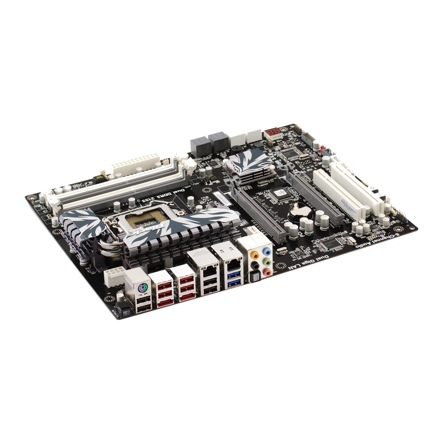
Page 13: Motherboard Components
• Audio, LAN, can be disabled in BIOS • F7 hot key for boot up devices option Form Factor • ATX Size, 305mm x 244mm Motherboard Components Introducing the Motherboard... - Page 14 Table of Motherboard Components LABEL COMPONENTS LGA1155 socket for 2 Generation Intel Core Family & 1. CPU Socket Unlock processors 2. CPU_FAN CPU cooling fan connector 3. DDR3_1~4 240-pin DDR3 SDRAM slots 4. CASE_FAN Case cooling fan connector 5. ATX_POWER Standard 24-pin ATX power connector 6.
-
Page 15: Installing The Motherboard
Chapter 2 Installing the Motherboard Safety Precautions • Follow these safety precautions when installing the motherboard • Wear a grounding strap attached to a grounded device to avoid dam- age from static electricity • Discharge static electricity by touching the metal case of a safely grounded object before working on the motherboard •... - Page 16 Do not over-tighten the screws as this can stress the motherboard. Installing the Motherboard...
-
Page 17: Installing Hardware
Installing Hardware Installing the Processor Caution: When installing a CPU heatsink and cooling fan make sure that you DO NOT scratch the motherboard or any of the surface-mount resis- tors with the clip of the cooling fan. If the clip of the cooling fan scrapes across the motherboard, you may cause serious damage to the motherboard or its components. -
Page 18: Cpu Installation Procedure
CPU Installation Procedure The following illustration shows CPU installation components. A. Opening of the Load Plate · Put your thumb on the tail of the load plate and press the tail down. · Rotate the load plate to fully open position. -
Page 19: Installing Memory Modules
1. To achieve better airflow rates and heat dissipation, we suggest that you use a high quality fan with 3800 rpm at least. CPU fan and heatsink installation procedures may vary with the type of CPU fan/ heatsink supplied. The form and size of fan/heatsink may also vary. 2. -
Page 20: Installation Procedure
1. For best performance and compatibility, we recommend that users give priority to the white DIMMs (DDR3_2/DDR3_4 when installing DIMMs. 2. We suggest users not mix memory type. It is recommended to use the same brand and type memory on this motherboard. Do not remove any memory module from its antistatic packaging until you are ready to install it on the motherboard. -
Page 21: Expansion Slots
Expansion Slots Installing Add-on Cards The slots on this motherboard are designed to hold expansion cards and connect them to the system bus. Expansion slots are a means of adding or enhancing the motherboard’s features and capabilities. With these efficient facilities, you can in- crease the motherboard’s capabilities by adding hardware that performs tasks that are not part of the basic system. - Page 22 Follow these instructions to install an add-on card: Remove a blanking plate from the system case corresponding to the slot you are going to use. Install the edge connector of the add-on card into the expansion slot. Ensure that the edge connector is correctly seated in the slot. Secure the metal bracket of the card to the system case with a screw.
-
Page 23: Connecting Optional Devices
Connecting Optional Devices Refer to the following for information on connecting the motherboard’s optional devices: F_AUDIO: Front Panel Audio header This header allows the user to install auxiliary front-oriented microphone and line- out ports for easier access. Signal Name Signal Name PORT 1L AUD_GND PORT 1R... - Page 24 SATA3~6: Serial ATAII connectors These connectors are used to support the Serial ATA 3Gb/s devices, simpler disk drive cabling and easier PC assembly. It eliminates limitations of the current Parallel ATA interface. But maintains register compatibility and software compatibility with Par- allel ATA.
- Page 25 USB3F: Front Panel USB 3.0 headers. This Motherboard implements one USB 3.0 header supporting 2 extra front USB 3.0 ports, which delivers 5Gb/s transfer rate. USB3F supports EZ Charger technology, provides about 1A current than general USB port in off mode for USB devices. It is useful and excellent, especially for the iPhone, iPad and iPod touch devices that need a large amount of current for faster recharging within less time.
-
Page 26: Installing Sata Hard Drives
Installing SATA Hard Drives This section describes how to install SATA devices such as a hard disk drive and a CD- ROM drive. About SATA Connectors Your motherboard features four SATA 3.0 Gb/s connectors and four SATA 6.0Gb/s connectors supporting a total of eight drives SATA refers to Serial ATA (Advanced Technology Attachment) is the standard interface for the SATA hard drives which are currently used in most PCs. -
Page 27: Connecting I/O Devices
Connecting I/O Devices The backplane of the motherboard has the following I/O ports: PS/2 Keyboard/Mouse Connect the PS/2 Keyboard or PS/2 Mouse to the PS/2 Combo Port combo port. Use the CLR_CMOS button to clear CMOS. CLR_CMOS Button Before clearing CMOS, make sure to turn off the power of the system. -
Page 28: Connecting Case Components
Connecting Case Components After you have installed the motherboard into a case, you can begin connecting the motherboard components. Refer to the following: Connect the CPU cooling fan cable to CPU_FAN. Connect the system cooling fan connector to SYS_FAN. Connect the power cooling fan connector to PWR_FAN. Connect the case switches and indicator LEDs to the PANEL. - Page 29 2. Connecting 8 power cable Users please note that the 8-pin and 4-pin power cables can both be con- nected to the ATX12V connector. When installing 8-pin power cable, the latches of power cable and the ATX12V connector match perfectly. 8-pin power cable CPU_FAN: CPU cooling FAN Power Connector Signal Name...
- Page 30 PWR_FAN: FAN Power Connector Signal Name Function System Ground Power +12V +12V Sense Sensor ATX12V: ATX 12V Power Connector Signal Name Signal Name Ground +12V Ground +12V Ground +12V Ground +12V Make sure to connect a 4-pin ATX power cable to ATX4P; otherwise, the system will be unstable.
-
Page 31: Panel Header
Panel Header The panel header (PANEL) provides a standard set of switch and LED headers commonly found on ATX or Micro ATX cases. Refer to the table below for informa- tion: Signal Function Signal Function HD_LED_P Hard disk LED(+) 2 FP PWR/SLP *MSG LED(+) HD_LED_N Hard disk LED(- ) FP PWR/SLP *MSG LED(-) - Page 32 Memo Installing the Motherboard...
-
Page 33: Using Bios
Chapter 3 Using BIOS About the Setup Utility The computer uses the latest “American Megatrends Inc. ” BIOS with support for Windows Plug and Play. The CMOS chip on the motherboard contains the ROM setup instructions for configuring the motherboard BIOS. The BIOS (Basic Input and Output System) Setup Utility displays the system’s configuration status and provides you with options to set system parameters. -
Page 34: Resetting The Default Cmos Values
Press the delete key to access BIOS Setup Utility. Aptio Setup Utility - Copyright (C) 2010 American Megatrends, Inc. Main Advanced Chipset M.I.B III Boot Security Save & Exit Choose the system default BIOS Information language System Language [English] System Date [Fri 10/22/2010] :Select Screen System Time... -
Page 35: Bios Navigation Keys
In this manual, default values are enclosed in parenthesis. Submenu items are denoted by a triangle The default BIOS setting for this motherboard apply for most conditions with optimum performance. We do not suggest users change the default values in the BIOS setup and take no responsibility to any damage caused by changing the BIOS settings. -
Page 36: Advanced Menu
Legacy OpROM Support Option ROM Launch PXE OpROM [Disabled] Launch Storage OpROM [Enabled] LAN Configuration :Select Screen ECS eJIFFY Function PC Health Status :Select Item Power Management Setup Enter : Select ACPI Settings +/- : Change Opt. CPU Configuration F1:General Help... -
Page 37: Lan Configuration
F3:Optimized Defaults F4:Save & Exit ESC:Exit Version 2.02.1205. Copyright (C) 2010, American Megatrends, Inc. ECS eJIFFY Function (Disabled) This item allows you to enable or disable ECS eJIFFY Function. Press <Esc> to return to the Advanced Menu page. Using BIOS... -
Page 38: Pc Health Status
PC Health Status On motherboards support hardware monitoring, this item lets you monitor the paeameters for critical voltages, temperatures and fan speeds. Aptio Setup Utility - Copyright (C) 2010 American Megatrends, Inc. Main Advanced Chipset M.I.B III Boot Security Save & Exit Smart Fan Function System Temperature 27°C... - Page 39 Smart Fan Mode (Normal) This item allows you to select the fan mode (Normal, Quiet, Silent, or Manual) for a better operation environment. If you choose Normal mode, the fan speed will be auto adjusted depending on the CPU temperature. If you choose Quite mode, the fan speed will be auto minimized for quiet environment.
- Page 40 Power Management Setup This page sets up some parameters for system power management operation. Aptio Setup Utility - Copyright (C) 2010 American Megatrends, Inc. Main Advanced Chipset M.I.B III Boot Security Save & Exit Power Management Setup About Resume by Ring Resume by RING [Disabled] Resume By PCI/PCI-E/Lan PME...
-
Page 41: Acpi Configuration
ACPI Configuration The item in the menu shows the highest ACPI sleep state when the system enters suspend. Aptio Setup Utility - Copyright (C) 2010 American Megatrends, Inc. Main Advanced Chipset M.I.B III Boot Security Save & Exit ACPI Settings Select the highest ACPI sleep state the system will enter ACPI Sleep State... -
Page 42: Cpu Configuration
CPU Configuration The item in the menu shows the CPU . Aptio Setup Utility - Copyright (C) 2010 American Megatrends, Inc. Main Advanced Chipset M.I.B III Boot Security Save & Exit Disabled for Windows XP CPU Configuration Intel (R) Core (TM) i5-2400 CPU @ 3.10GHz EMT64 Supported Processor Speed... - Page 43 Limit CPUID Maximum (Disabled) Use this item to enable or disable the maximum CPUID value limit. When supports Prescott and LGA775 CPUs, enables this to prevent the system from “rebooting” when trying to install Windows NT 4.0. Excute Disable Bit (Enabled) This item allows the processor to classify areas in memory by where application code can execute and where it cannot.
-
Page 44: Sata Configuration
SATA Configuration Use this item to show the mode of serial SATA configuration options. Aptio Setup Utility - Copyright (C) 2010 American Megatrends, Inc. Main Advanced Chipset M.I.B III Boot Security Save & Exit (1) IDE Mode. (2) AHCI Mode. SATA Configuration (3) RAID Mode. -
Page 45: Usb Configuration
USB Configuration Use this item to show the information of USB configuration. Aptio Setup Utility - Copyright (C) 2010 American Megatrends, Inc. Main Advanced Chipset M.I.B III Boot Security Save & Exit USB Configuration Enabled/Disabled All USB Devices All USB Devices [Enabled] USB 3.0 Controller [Enabled]... -
Page 46: Super Io Configuration
Super IO Configuration Use this item to show the information of Super IO configuration. Aptio Setup Utility - Copyright (C) 2010 American Megatrends, Inc. Main Advanced Chipset M.I.B III Boot Security Save & Exit Set Parameters of Serial Port Super IO Configuration 0 (COMA) Super IO Chip IT8728... -
Page 47: Chipset Menu
Chipset Menu The chipset menu items allow you to change the settings for the North chipset, South chipset and other system. Aptio Setup Utility - Copyright (C) 2010 American Megatrends, Inc. Main Advanced Chipset M.I.B III Boot Security Save & Exit North Bridge Parameters North Bridge South Bridge... - Page 48 South Bridge Scroll to this item and press <Enter> to view the following screen. Aptio Setup Utility - Copyright (C) 2010 American Megatrends, Inc. Main Advanced Chipset M.I.B III Boot Security Save & Exit South Bridge Specify what state to go to when power is re-applied after Restore AC Power Loss [Power Off]...
- Page 49 ME Subsystem Scroll to this item and press <Enter> to view the following screen. Aptio Setup Utility - Copyright (C) 2010 American Megatrends, Inc. Main Advanced Chipset M.I.B III Boot Security Save & Exit Intel ME Subsytem Configuration ME Subsystem Help ME Version 7.0.0.1135 ME Subsystem...
-
Page 50: Mb Intelligent Bios Iii) Menu
M.I.B III (MB Intellient BIOS III) Menu This page enables you to set the clock speed and system bus for your system. The clock speed and system bus are determined by the kind of processor you have installed in your system. Aptio Setup Utility - Copyright (C) 2010 American Megatrends, Inc. - Page 51 ICC Over-Clocking Lib Version (7.0.0.29) This item shows the ICC over-clocking lib version. Number of ICC Profiles (N/A) This item shows number of ICC profiles. Current ICC Profiles Index (N/A) This item shows current ICC profiles index. ICC Enable (Disabled) This item allows you to enable or disable current ICC.
- Page 52 CPU Ratio (31) This item allows users to control non turbo CPU ratio. IA Core Current (Normal) Use this item to control CPU Current Limit. This is for Turbo mode. Power Limit 1 Value (Watt) (95) Use this item to control the limit of the TDP. This is for Turbo mode. Power Limit 2 Switch (Enabled) Use this item to control the Power Limit 2.
- Page 53 Chipset Configuration Scroll to this item to view the following screen: Aptio Setup Utility - Copyright (C) 2010 American Megatrends, Inc. Main Advanced Chipset M.I.B III Boot Security Save & Exit Memory Mutiplier Memory Multiplier Configuration Memory Mutiplier [10.67] :Select Screen Memory Timing Configuration :Select Item CAS# Latency (tCL)
-
Page 54: Boot Menu
Boot Menu This page enables you to set the keyboard NumLock state. Aptio Setup Utility - Copyright (C) 2010 American Megatrends, Inc. Main Advanced Chipset M.I.B III Boot Security Save & Exit Select the keyboard NumLock Boot Configuration state Bootup NumLock State [On] Quiet BOOT [Enabled]... -
Page 55: Security Menu
Security Menu This page enables you to set setup administrator and password. Aptio Setup Utility - Copyright (C) 2010 American Megatrends, Inc. Main Advanced Chipset M.I.B III Boot Security Save & Exit Set Setup Administrator If ONLY the Administrator’s password is set, Password then this only limits access to Setup and is only asked for when entering Setup. - Page 56 Aptio Setup Utility - Copyright (C) 2010 American Megatrends, Inc. Main Advanced Chipset M.I.B III Boot Security Save & Exit Set Setup Administrator If ONLY the Administrator’s password is set, Password then this only limits access to Setup and is only asked for when entering Setup.
-
Page 57: Save & Exit Menu
Save & Exit Menu This page enables you to exit system setup after saving or without saving the changes. Aptio Setup Utility - Copyright (C) 2010 American Megatrends, Inc. Main Advanced Chipset M.I.B III Boot Security Save & Exit Exit system setup after saving Save Changes and Exit the changes. -
Page 58: Updating The Bios
Boot Override Use this item enables you to set the device order. SATA: SONY DVD RW DRU-190S Use this item enables you to set the device order. SATA: ST3306260AS Use this item enables you to set the device order. Updating the BIOS You can download and install updated BIOS for this motherboard from the manufacturer’s Web site. -
Page 59: Using The Motherboard Software
Chapter 4 Using the Motherboard Software About the Software DVD-ROM/CD-ROM The support software DVD-ROM/CD-ROM that is included in the motherboard package contains all the drivers and utility programs needed to properly run the bundled products. Below you can find a brief description of each software program, and the location for your motherboard version. -
Page 60: Running Setup
Drivers Click the Setup button to run the software installation program. Setup Select from the menu which software you want to install. Click the Utilities button to display the application software and Utilities other software utilities that are available on the disk. Select the sofware you want to install then follow installation procedure. - Page 61 Click Next. The following screen appears: Check the box next to the items you want to install. The default options are recom- mended. Click Next run the Installation Wizard. An item installation screen appears: Follow the instructions on the screen to install the items. Drivers and software are automatically installed in sequence.
-
Page 62: Manual Installation
Windows Vista/7 will appear below UAC (User Account Control) message after the system restart. You must select “Allow” to install the next driver. Continue this process to complete the drivers installation. Manual Installation Insert the disk in the DVD-ROM/CD-ROM drive and locate the PATH.DOC file in the root directory. -
Page 63: Ati Crossfire
Chapter 5 ATI CrossFireX Technology Support This motherboard supports the ATI CrossFireX Technology that allows you to install multi-graphics processing units (GPU) graphics cards. Follow the installation procedures in this section. Requirements Two identical CrossFireX ready graphic cards are needed for the setup of 2-way CrossFireX configuration. - Page 64 2. Connect the cable from your monitors to the CrossFireX ready graphics card installed on the PCIEX16_1 slot. Monitor Cable * For reference only 3. Connect an auxiliary power source from the power supply to the graphics cards. ATI CrossFire Technology Support...
-
Page 65: The Catalyst Tm Control Center Dialog Box
The Catalyst Control Center Dialog Box To enable CrossFireX • Install ATI graphic card driver. • Enter the Catalyst Control Center Dialog Box. • check the “Enable CrossFireX ” item. • Click OK to apply. ATI CrossFire Technology Support... - Page 66 Memo ATI CrossFire Technology Support...
-
Page 67: Technology Support
Chapter 6 ® ® ® ® ® ® ® ® ® ® NVIDIA Technology Support ® ® This motherboard supports the NVIDIA Technology that allows you to install multi-graphics processing units (GPU) graphics cards. Follow the installation proce-dures in this section. Requirements ®... - Page 68 2. Connect the cable from your monitors to the SLI-Ready graphics card installed on the PCIEX16_1 slot. Monitor Cable ® ® ® ® ® Once the new NVIDIA SLI-certified components have been installed in the system,they will be recognized by the operating system upon Windows boot-up. A Found NewHardware message will be displayed: NVIDIA®...
-
Page 69: Enabling Nvidia Sli
® Enabling NVIDIA 1. Click on the SLI capable system message to open the following window. Description: ® All NVIDIA GPUs work together with SLI technology to increase the rendering performance of your 3D applications. Typical usage scenarios: • Playing 3D games •... - Page 70 Select the checkbox Enable SLI technology and then click Apply ® You now have an NVIDIA SLI-enabled PC! ® You can also access these settings by opening the NVIDIA Control Panel (right- click on desktop), clicking on 3D Settings (shown below) and then selecting “SetSLI configuration”.
-
Page 71: Setting Up Ejiffy
Note: eJIFFY is ECS optional feature utility corresponding to the DVD activation and BIOS setup. Please check the hard copy user’s guide or product color-box to see if the model has embodded eJIFFY feature. -
Page 72: Installation And Bios Setup
DVD Activation Finish the DVD utility setup, and then set the BIOS to complete eJIFFY activation. 1. Insert ECS software utility DVD and enter below “Utilities” screen. Click eJIFFY feature item to install. 2. Follow the onscreen instructions to finish eJIFFY setup. - Page 73 3. After setting up eJIFFY under Windows, you can switch eJIFFY display/keyboard language from English to your local language. The changes will be applied after rebooting. Note: The keyboard language selection list offers several more regional keyboard setups to switch with the default English typing. Please refer to the usage FAQ for more tips.
- Page 74 Setup button on the post screen to enter the BIOS setup page after boot up. 5. And then enter the Advanced Setup page to enable the item ECS eJIFFY Func- tion. Press F4 to save the configuration and exit. Restart your computer.
-
Page 75: Entering Ejiffy
Entering eJIFFY The post screen appears within several seconds after boot up and it has three buttons on it, Operating system, eJIFFY and BIOS Setup. Click to enter the normal OS you have installed such as Windows. Click to enter eJIFFY OS. Click to set the BIOS. -
Page 76: Features Icons
Feature Icons The following illustration shows the main feature icons that eJIFFY provides on the menu. eWeb: Firefox for web browsing/webmail and watching flash video. ePix: Photo viewing. ePal: On-line chat tool to use the most popular IMs in the world. (MSN, ICQ , AIM, etc.) Shows ePal on-line connection status. -
Page 77: Usage Faq
Usage FAQ Language Control Panel: Besides setting English as the default interface, eJIFFY offers multi-language displays and keyboard settings for language- switch. Open the language control panel to select a preferable language setting. Keyboard Language Setup Step1. Click to open the language control panel. Step 2: Click “Keyboard Language”... - Page 78 Click to enable all possible language inputs you want to apply, and click “Apply”: Move your mouse pointer on the text box and press Ctrl+Space. The language bar will then appear as fol- lows. Click the language bar here. Select your desired language Setting Up eJIFFY...
- Page 79 How to change display language? Open the Language Control Panel and click to show the display language list. Check your desired display language. Your selected display language will be applied after rebooting. How to set networking connection? If you do not have IP shared server(direct link), you can select the icon and press the right key of your mouse.
- Page 80 Step1 Select the icon , press the right key of your mouse, then select “Edit Connection...” item. Step2 Select the connection you want (eg. Wired) and click “+Add” button. Types of connections (1) Wired connection Setting Up eJIFFY...
- Page 81 (2) Wireless connection (3) DSL connection Note: Details about eJIFFY please refer to eJIFFY in disk. Setting Up eJIFFY...
- Page 82 Memo Setting Up eJIFFY...
-
Page 83: Intel ® Matrix Storage Manager Raid Configurations
Chapter 8 Intel Matrix Storage Manager RAID Configurations ® ® The Intel Matrix Storage Manager allows you to configure RAID 0, and 1 sets on the external Serial ATA hard disk drives. Before creating a RAID set Prepare the following items: One SATA HDD. -
Page 84: Entering Intel ® Matrix Storage Manager Raid Bios Utility
® Entering Intel Matrix Storage Manager RAID BIOS util- ® During POST, press <Ctrl-I> to enter the Intel Matrix Storage Manager RAID BIOS menu. ® The main Intel Matrix Storage Manager RAID BIOS menu appears. Use the arrow keys to move the color bar and navigate through the items. Intel Matrix Storage Manager RAID Configurations ®... -
Page 85: Creating A Raid Set
Creating a RAID set In the main Intel ® Matrix Storage Manager RAID BIOS menu, highlight Create RAID Volume using the up/down arrow key then press <Enter>. When the RAID Level item is highlighted, use the up/down arrow key to select the RAID set that you want to create. - Page 86 When done, press <Enter> to confirm the creation of the RAID set. A dialogue box appears to confirm the action. Press <Y> to confirm; other- wise, press <N>. Pressing <Y> deletes all the data in the HDDs. The following screen appears, displaying the relevant information about the RAID set you created.
-
Page 87: Deleting A Raid Set
Deleting a RAID set In the main Intel ® Matrix Storage Manager RAID BIOS menu, highlight Delete RAID Volume using the up/down arrow key then press <Enter>. Use the space bar to select the RAID set you want to delete. Press the <Del>... -
Page 88: Resetting Disks To Non-Raid
Resetting disks to Non-RAID An HDD that has been previously configured as part of another RAID set in another platform is called a broken RAID HDD. When you install a broken RAID HDD, you cannot select this disk when configuring a RAID ®... -
Page 89: Marvell 88Se9128 Sata 6Gb/S Raid Controller Bios Setup
Chapter 9 Marvell 88SE9128 SATA 6Gb/s RAID Controller BIOS Setup The 88SE9128 controller supports the creation of RAID 0 and RAID 1 virtual disks comprising of exactly two SATA physical disks. The following shows the messages displayed during the POST of P67H2-A motherboard. - Page 90 2. Use the arrow keys to scroll the list of free disks. Press Space to select/unselect a disk and press Enter to continue. An asterisk will appear to the left of the selected disks. Marvell 88SE9128 SATA 6Gb/s RAID Controller BIOS Setup...
- Page 91 3. Create Virtual Disk by configuring its settings in the Information pane. 4. Press Enter to select a RAID Level (RAID 0, RAID1). Marvell 88SE9128 SATA 6Gb/s RAID Controller BIOS Setup...
- Page 92 5. Scroll to Stripe Size and press Enter to select 32K or 64K for the selected RAID Level. 6. Scroll to Gigabyte Rounding and press Enter to select None, 1G or 10G. Marvell 88SE9128 SATA 6Gb/s RAID Controller BIOS Setup...
- Page 93 7. Scroll to Quick Init and press Enter to select Yes or No. 8. Scroll to VD Name to type a new name, and press Enter to confirm the selection. Marvell 88SE9128 SATA 6Gb/s RAID Controller BIOS Setup...
- Page 94 9. Scroll to Next and press Enter to create the virtual disks after configuring the virtual disk. Then press Y to select YES. The virtual disk is now listed in the Topology pane. Marvell 88SE9128 SATA 6Gb/s RAID Controller BIOS Setup...
-
Page 95: Trouble Shooting
Chapter 10 Trouble Shooting Start up problems during assembly After assembling the PC for the first time you may experience some start up problems. Before calling for technical support or returning for warranty, this chapter may help to address some of the common questions using some basic troubleshooting tips. -
Page 96: Start Up Problems After Prolong Use
c) The PC suddenly shuts down while booting up. 1. The CPU may experience overheating so it will shutdown to protect itself. Ensure the CPU fan is working properly. 2. From the BIOS setting, try to disable the Smartfan function to let the fan run at default speed. - Page 98 Memo...
-
Page 99: Post Code Checkpoints
POST Code Checkpoints The POST code checkpoints are the largest set of checkpoints during the BIOS pre-boot process. The following table describes the type of checkpoints that may occur during the POST portion of the BIOS : Checkpoint Description 01-0F SEC Status Codes &... - Page 100 CPU post-memory initialization. Boot Strap Processor (BSP) selection CPU post-memory initialization. System Management Mode (SMM) initialization Post-Memory North Bridge initialization is started Post-Memory North Bridge initialization (North Bridge module specific) Post-Memory North Bridge initialization (North Bridge module specific) Post-Memory North Bridge initialization (North Bridge module specific) Post-Memory South Bridge initialization is started Post-Memory South Bridge initialization (South Bridge module specific) Post-Memory South Bridge initialization (South Bridge module specific)
- Page 101 FB-FF Reserved for future AMI error codes Memory not Installed Memory was installed twice (InstallPeiMemory routine in PEI Core called twice) Recovery started DXEIPL was not found DXE Core Firmware Volume was not found Reset PPI is not available Recovery failed S3 Resume failed DXE Core is started NVRAM initialization...
- Page 102 9E-9F Reserved for future AMI codes IDE initialization is started IDE Reset IDE Detect IDE Enable SCSI initialization is started SCSI Reset SCSI Detect SCSI Enable Setup Verifying Password Start of Setup Reserved for ASL (see ASL Status Codes section below) Setup Input Wait Reserved for ASL (see ASL Status Codes section below) Ready To Boot event...