Extron electronics DXP DVI Pro User Manual
Hide thumbs
Also See for DXP DVI Pro:
- User manual (140 pages) ,
- Setup manual (48 pages) ,
- User manual (139 pages)

Related Manuals for Extron electronics DXP DVI Pro


Summary of Contents for Extron electronics DXP DVI Pro
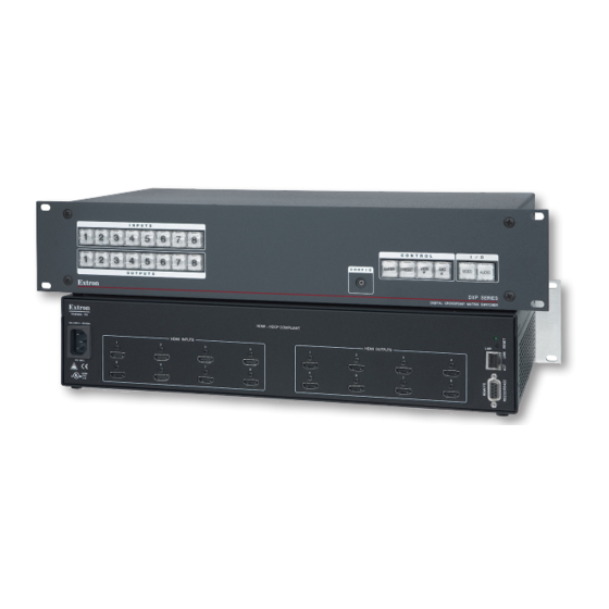
- Page 1 User Guide Matrix Switchers DXP DVI Pro DXP HDMI DVI and HDMI Series Digital Matrix Switchers 68-1370-01 Rev. 04 12...
- Page 2 Warning This equipment should be operated only from the power source indicated on the product. This This symbol is intended to alert the user of important operating and mainte- equipment is intended to be used with a main power system with a grounded (neutral) conductor. The third nance (servicing) instructions in the literature provided with the equipment.
- Page 3 FCC Class A Notice This equipment has been tested and found to comply with the limits for a Class A digital device, pursuant to part 15 of the FCC Rules. Operation is subject to the following two conditions: This device may not cause harmful interference. This device must accept any interference received, including interference that may cause undesired operation.
- Page 4 Conventions Used in this Guide In this user guide, the following are used: CAUTION: A caution indicates a potential hazard to equipment or data. NOTE: A note draws attention to important information. TIP: A tip provides a suggestion to make working with the application easier. WARNING: A warning warns of things or actions that might cause injury, death, or other severe consequences.
-
Page 5: Table Of Contents
Commands ..........55 ......33 IP-specific SIS Commands ........66 Symbol Definitions for IP-specific Outputs ............34 Commands ..........66 Command and Response Table for Output ............35 IP-Specific SIS Commands ......68 DXP DVI Pro and DXP HDMI Series... - Page 6 IP Settings Fields ......... 106 Date/Time Settings Fields ......107 Passwords Page........... 108 ........109 ......111 ....113 ........... 113 Adding a Directory ........114 Other File Management Activities ....114 ..... 114 ........116 DXP DVI Pro and DXP HDMI Series...
-
Page 7: Introduction
Introduction significant features of the series, and provides application diagrams. About this Guide About the DXP DVI Pro and DXP HDMI Series Digital Matrix Switchers Features Application Diagrams About this Guide This guide contains installation, configuration, and operating information for the The terms “DXP,“... -
Page 8: Features
Inputs and outputs on HDMI connectors DVI signal support removed or decoded from the data stream. Automatic cable equalization for each input to 100 feet (30.4 m) at 1920x1200 DXP DVI Pro and DXP HDMI All DXP series feature the following: HDMI standard support formats. - Page 9 Audio breakaway — An embedded audio signal can be separated from its corresponding video signal within the switcher, allowing the audio and video signals from one source to be switched to different destinations 32 global presets — Frequently used I/O configurations can be saved and recalled as global presets either from the front panel, IP Link, or serial control.
-
Page 10: Application Diagrams
Application Diagrams Display 1 Display 3 Display 7 Display 5 Display 8 Display 2 Display 6 Display 4 HDMI - HDCP COMPLIANT Extron HDMI INPUTS HDMI OUTPUTS HDMI 201 Tx Extron HDMI Twisted IPL 250 Pair Extender LISTED IP Link Ethernet 1T23 HDMI 201 Tx I.T.E. - Page 11 CONTROL DVI-D OUTPUT PASS THRU Tx Rx DVI 201 Rx SERIES DVI 201 Rx TouchLink ™ Control System DXP DVI Pro Series HDCP-compliant DVI Matrix Switcher DVI PRO - HDCP COMPLIANT TCP/IP DVI-D INPUTS DVI-D OUTPUTS IPL 250 ® INPUT...
-
Page 12: Installation
DXP DVI Pro 84 – 8 inputs and 4 outputs DXP DVI Pro 48 – 4 inputs and 8 outputs DXP DVI Pro 44 – 8 inputs and 4 outputs... - Page 13 NOTE: The illustration on the previous page shows a DXP 88 HDMI, with eight eight number of inputs and outputs: DXP HDMI 84 – 8 inputs and 4 outputs DXP HDMI 48 – 4 inputs and 8 outputs DXP HDMI 44 – 4 inputs and 4 outputs AC power connector Input connectors —...
- Page 14 NOTE: LockIt ® cable connections. For information on attaching the LockIt brackets, see the LockIt HDMI Lacing Bracket Installation Guide at www.extron.com. Output connectors — DVI Pro series: connectors. HDMI series: output connectors. NOTE: The switchers do not alter the video signal in any way. The signal that is output by the switcher is in the same format as the input signal.
-
Page 15: Connections
Connections WARNING: Remove power from the system before making any connections. CAUTION: although you may not feel, see, or hear it. Ethernet Connection 328 feet (100 m). NOTES: Do not use standard telephone cables. Telephone cables do not support Do not stretch or bend the cables, because this can cause transmission errors. -
Page 16: Rs-232 And Rs-422 Remote Connections
RS-232 and RS-422 Remote Connections The DXP switchers have two serial ports through which the DXPs can be configured via SIS commands (serial commands that control the switcher through this connector). Remote RS232/RS422 port (rear panel) The following figure shows the pin assignments for the Remote RS232/RS422 connector. RS-232 Function RS-422 Function... -
Page 17: Operation
Operation This section describes the DXP front panel controls and the procedures for configuring and operating the DXP switchers. Topics include: Definitions Front Panel Controls and Indicators Powering On Creating a Configuration Viewing a Configuration I/O Grouping Saving and Recalling Presets Muting and Unmuting Video and Audio Outputs Locking and Unlocking the Front Panel (Executive Modes) Resetting... -
Page 18: Front Panel Controls And Indicators
Room — A subset of outputs that are logically related to each other, as determined by the operator. The switchers support up to 10 rooms, each of which can consist of 1 Room memory preset — A configuration consisting of outputs in a single room current configuration for the outputs assigned to that room only (none of the other outputs are affected). - Page 19 Input and Output Buttons of how many inputs and outputs it actually has. On models with four inputs or outputs, buttons 5 through 8 behave like buttons 1 through 4, selecting inputs or outputs 1 through 4. The following table summarizes the button functions. Primary Functions through Action:...
-
Page 20: Configuration Port
Secondary functions ( ): Select a global preset (see “Saving and Recalling Presets” on page 32). Output 1 only: mode (see “I/O Grouping” on page 28). Mute and unmute an output (see “Muting and Unmuting Video and Audio Outputs” on page 34). Configuration Port Config port —... - Page 21 Secondary functions ( ): In I/O grouping mode, selects group 1 (see “I/O Grouping” on page 28). In I/O grouping mode, indicates that group 1 is selected. < > buttons, places the switcher in serial port configuration mode (see “Selecting the RS-232/RS-422 Protocol and Baud Rate (Rear Panel)”...
- Page 22 > > button button does the following: Primary functions (❏): ❏ Cancels operations or selections in progress and resets the front panel button indicators. > NOTE: The Esc button does not reset the current configuration or any presets. ❏ Indicates that the escape function has been activated (flashes once). Secondary functions ( ): In I/O grouping mode, selects group 4 (see “I/O...
- Page 23 Secondary functions ( ): (lock mode 2 and lock mode 0) (see “Locking and Unlocking the Front Panel (Executive Modes)” on page 37). lock mode 1). “Resetting the System from the Front Panel” on page 38). Selects the RS-232 protocol for the rear panel Remote RS232/RS422 port in serial port selection and configuration mode and indicate the selection (see “Selecting the RS-232/RS-422 Protocol and Baud Rate (Rear...
-
Page 24: Powering On
Powering On and to an AC source. The switcher performs a self-test that flashes the front panel button indicators red, green, and amber and then turns them off. An error-free power-up self-test sequence leaves all I/O and control buttons either unlit or showing background was when the switcher was previously powered off. - Page 25 Repeat steps 1 through 4 to create or clear additional ties until the desired configuration is complete. NOTES: Only one input can be tied to an output. If you tie an input to an output that is already tied to another input, the older tie is broken in favor of the newer tie.
- Page 26 Press and release the Input 5 button. Press and release the Input 5 button. The button lights amber. INPUTS Figure 14. Select Input 5 Press and release the Output 3, Output 4, and Output 8 buttons. Press and release the Output 3, Output 4, and Output 8 buttons. The buttons blink amber to indicate that the selected input will be tied to these outputs.
- Page 27 Example 2: Adding a Tie to a Set of Video Ties In the following example, a new tie is added to the current configuration. The illustrations show the front panel indications that result from your actions. NOTE: This example assumes that you have performed example 1. >...
-
Page 28: Ties
Press the Enter button to confirm the configuration change. All input and output buttons become unlit or return to ENTER background illumination. The Enter button becomes unlit or returns to background illumination. Figure 22. Confirm the Tie The configuration now is: Input 5 video tied to output 1, output 3, output 4, and output 8 Input 5 audio tied to output 3, output 4, and output 8 Figure 23. -
Page 29: Ties
Example 3: Removing a Tie from a Set of Ties In the following example, an existing tie is removed from the current configuration. The steps show the front panel indications that result from your action. NOTE: This example assumes that you have performed examples 1 and 2. >... - Page 30 Press the Enter button to confirm the configuration change. All input and output buttons become unlit or return to ENTER background illumination. The Enter button becomes unlit or returns to background illumination. Figure 28. Confirm the Tie Removal The configuration now is: Input 5 video tied to output 1, output 3, and output 8 Input 5 audio tied to output 3 and output 8 Input 5 video and audio tied to output 3 and output 8...
- Page 31 Select the desired input or outputs whose ties you wish to view by pressing the input and output buttons. NOTES: view-only mode, all output buttons without ties light. Likewise, when you press an output button with no ties, all other output buttons without ties light.
- Page 32 buttons as necessary until both are lit. Press the Video button to Press the Audio button I / O toggle video on and off. to toggle audio on and off. AUDIO VIDEO The button lights green when selected. The button lights red when selected.
- Page 33 toggle it to either unlit or background-illuminated. Press the Audio Press the Video button I / O button to deselect it. to select it. VIDEO AUDIO The button is unlit The button lights green or background when selected. illuminated when deselected.
- Page 34 I/O Grouping I/O grouping is a matrix switcher feature that allows you to subdivide the front panel control of the matrix into four smaller functional sub-switchers. Inputs and outputs can be assigned to one of four groups or not assigned to any group. to a group can be tied only to other outputs and inputs within the same group.
- Page 35 Press and release one of the control buttons to select a group: C O N T R O L Press the Preset button to select group 2 (shown at VIEW ENTER PRESET right). Group # Select the desired inputs and outputs to assign to the group by pressing their buttons. mode to time out after approximately 30 seconds.
- Page 36 To enter I/O group mode, press and hold the Input 1 and Output 1 buttons until all buttons that are not grouped light green (approximately 2 seconds). Release the Input 1 button and Output 1 button. Ungrouped input and output buttons light. INPUTS INPUTS Press and hold...
- Page 37 Press and release the Preset button to select group 2. Press and release the Preset button to select group 2. The button lights to indicate the selection. C O N T R O L VIEW ENTER PRESET Group # Figure 41. Select I/O Group 2 Press and release the desired input and output buttons.
-
Page 38: Saving And Recalling Presets
Saving and Recalling Presets The current configuration (0) can be saved as a preset in any one of 32 preset memory addresses. Preset locations are assigned to the input buttons and (where necessary) output current configuration. NOTES: Presets cannot be viewed from the front panel unless recalled as the current configuration. - Page 39 Press and hold the Preset button until it blinks (approximately 2 seconds). Preset Assigned Press and hold the Preset button until it blinks. INPUTS PRESET PRESET 2 seconds All input buttons with assigned presets light. If you then save the configuration to a lit preset number, the No Preset Assigned configuration data at that preset...
-
Page 40: Outputs
Press and release the Preset button. Press and release the Preset Assigned Preset button. The Preset button lights. INPUTS PRESET All input buttons with assigned presets light. No Preset Assigned Figure 50. Enter Recall Preset Mode Press and release the input or output button for the desired preset. Press and release the Input 1 button. -
Page 41: Output
NOTES: on and off. without ties. restored, the mute settings are retained. Example 8: Muting and Unmuting an Output In the following example, several switcher outputs are muted and unmuted. The steps show the front panel indications that result from your action. Press the Esc button to clear all selections. - Page 42 One at a time, press and hold the Output 3 button and then the Output 4 button until each button begins to blink (approximately 2 seconds). The output 3 and output 4 video and audio signals are muted. Mute outputs one at a time. Press and hold the Output 3 button.
- Page 43 Locking and Unlocking the Front Panel (Executive Modes) The matrix switchers have three levels of front panel security lock that limit the operation of the switcher from the front panel: Lock mode 0 — The front panel is completely unlocked. All front panel functions are available.
-
Page 44: Switching From Lock Mode 1 To Lock Mode 0
Selecting Lock Mode 2 or Toggling Between Mode 2 and Mode 1 NOTE: If the switcher is in lock mode 0 or mode 1, this procedure selects mode 2. If the switcher is in lock mode 2, this procedure selects mode 1. following buttons blink twice (approximately 2 seconds). - Page 45 To reset the switcher to the factory default settings, press and hold buttons while you apply AC power to the switcher. NOTE: System reset does not reset the Internet protocol (IP) settings or replace user-installed firmware. Press and hold the Video and Audio buttons while you apply power to the switcher.
- Page 46 The table below provides a summary of the reset modes . Reset Modes Summary Mode Activation Result Purpose/Notes Restores the factory-installed firmware. It Mode 1 can be power to the switcher. does not clear the current configuration. used to remove a version of firmware if incompatibility issues arise.
- Page 47 To perform a soft reset of the switcher: hold the rear panel Reset button until system reset), or three times (for an absolute reset). Release, then immediately Press and hold Reset LED flashes once. press and release again. the Reset button. 3 seconds Events Reset (Level 3)
-
Page 48: Selecting The Rs-232/Rs-422 Port Protocol
Setting the Button Background Illumination The buttons on the front panel can be set to have amber background illumination at all times or the background illumination can be turned off. To toggle the background illumination on and off, press and hold the Input 1 and Input 2 buttons simultaneously until the button background illumination changes (approximately 2 seconds. -
Page 49: Troubleshooting
To change a value, press and release the button that selects the desired value (see figure 64). Press and release the buttons to configure the RS-232/RS-422 port as follows: Baud rate: Enter — 9600 Preset — 19200 View — 38400 Esc —... - Page 50 Configuration Worksheets Instead of trying to remember the configuration for each preset, use worksheets to record this information. Make copies of the blank worksheet at the end of this section, and use one sheet for each preset configuration. Cross out all unused or inactive inputs and outputs.
- Page 51 Worksheet Example 2: Daily Configuration The following figure continues from worksheet example 1 by showing the video ties that make up the configuration of preset 1. A solid ink line shows video ties. Input Sources Editing DVI PRO/ DVI PRO/ DVI PRO/ Editing Station...
- Page 52 Worksheet Form Input Sources Output Destinations Title: Preset # Fill in the preset number and use colors, dashes, and so forth to make connecting lines. Disregard or cross out the input and output boxes that do not apply to your switcher.
-
Page 53: Sis Configuration And Control
SIS Configuration and Control Instruction Set (SIS) commands can be issued, and lists the commands that are available for controlling and configuring the DXP switchers. Topics include: Serial Ports Ethernet Port Host to Switcher Instructions Switcher-initiated Messages Switcher Error Responses Using the Command and Response Tables for SIS Commands SIS Commands for DXP IP-specific SIS Commands... -
Page 54: Default Ip Addresses
Ethernet Port if necessary, via SIS. For information on connecting via Telnet, see “Connecting as a Telnet Client” on page 129. are identical to the commands and behavior the product exhibits when you are communicating with it via a serial port. Ethernet Cable through cable or a crossover cable. -
Page 55: Connection Timeouts
-01 is the DXP part number. With an RS-232 or RS-422 connection: (c) Copyright 2011, Extron Electronics DXP DVI-HDMI, Vn.nn, 60-nnnn-01 The switcher initiates the copyright message if it is powered on while connected to the computer. With an Ethernet connection: (c) Copyright 2011, Extron Electronics DXP DVI-HDMI, Vn.nn, 60-nnnn-01... - Page 56 Password: The switcher initiates the password message immediately after the copyright message when the controlling system is connected using TCP/IP or Telnet and the switcher is password protected. This message means that the switcher requires an administrator or user level password before it will respond to the commands entered via this link. NOTE: The Password prompt is redisplayed if an incorrect password is entered.
-
Page 57: For Sis Commands
Switcher Error Responses command and sends a response to the host device. If the switcher is unable to perform the command because the command is invalid or contains invalid parameters, the switcher returns an error response to the host. The error response codes are: —... -
Page 58: Sis Commands For Dxp
SIS Commands for DXP Symbol Definitions for DXP = Carriage return and line feed = Carriage return (no line feed) NOTE: Input and output numbers in commands may be entered as either one-digit, two- digit, or three-digit numbers. All input and output numbers are reported as two-digit numbers in the response. - Page 59 01 – 40 32 = 720p (default) data information consists of the resolution, refresh rate, and pixel clock information of a display outputs on your DXP) 9 through 36) connected to output 1 (numbers 37 through 40) EDID Table — DDC Source Selection SIS Value Resolution Refresh (Hz)
- Page 60 NOTES: Multi-channel audio consists of: 2-channel audio (stereo) 8-channel audio AC-3 6-channel audio 8-channel audio 8-channel audio 8-channel audio AC-3 8-channel audio 8-channel audio 2-channel audio consists of PCM, 2-channel audio (stereo). = Firmware version number Shown to second decimal place (n.nn) description, and upload date and time 0 = no sync...
-
Page 61: Command And Response Table For Dxp Sis Commands
Command and Response Table for DXP SIS Commands ASCII Command Response Command Additional Description (Host to Switcher) (Switcher to Host) Create Ties Commands can be entered back-to-back in a string, with no spaces. Example: 1*1!02*02&003*003%4*8$ NOTES: The quick multiple tie and tie input to all output commands activate all I/O switches simultaneously. The DXP switchers support 1-, 2-, and 3-digit numeric entries (1*1!, 02*02&, or 003*003%). - Page 62 Mut01002300 Example: Output 2 video, Output 5 audio, and Output 6 video DXP DVI Pro 88 and audio are muted. All other outputs are unmuted. NOTE: The “Mut” portion of the response appears only when the switcher is in verbose mode 2 or 3 (see the verbose mode command on page 69).
- Page 63 ASCII Command Response Command Additional Description (Host to Switcher) (Switcher to Host) Save, Recall, and Directly Write Global and Room Presets (continued) X& &), $... & Directly write a The tie all (! global preset tie video (%), and tie audio ($) X&] commands are all valid.
- Page 64 Mut01002300 Example: Output 2 video, Output 5 DXP DVI Pro 88 audio, and Output 6 video and audio are muted. All other outputs are unmuted. The Mut portion of the response appears only when the switcher is in verbose mode 2 or 3 (see the...
- Page 65 ASCII Command Response Command Additional Description (Host to Switcher) (Switcher to Host) View Ties and Presets (continued) EX& X@ X@ X& *1*1VC Show preset video configuration configuration. Show the input ) tied to 16 sequential outputs, starting from output 1. NOTES: For all DXP models, the starting output number is 1.
- Page 66 Example: Input 2 not Input 8 in Input 1 in grouped group 2 DXP DVI Pro 88 group 4 DXP HDMI 88 4 0 1 3 3 0 0 2 Response #s = group: Input: 2 3 4 5 6 7 8 Input 1 –...
- Page 67 ASCII Command Response Command Additional Description (Host to Switcher) (Switcher to Host) Names EX& , X1# X& , X1#] X& Assign global preset name 1,Security 1NG Nmg01 Security 1 Example: Name global preset 1 Security 1. EX& X1#] Read global preset name X&...
- Page 68 ASCII Command Response Command Additional Description (Host to Switcher) (Switcher to Host) HDCP Authorization NOTE: *1HDCP HdcpE for input *0HDCP HdcpE E X! X2$] *HDCP HdcpE status status for input Resets Reset global presets Clear all global presets and and names their names.
- Page 69 ASCII Command Response Command Additional Description (Host to Switcher) (Switcher to Host) Information Requests (continued) 60-nnn[n]-01 60-875-01 Request part number 60-1009-01 60-876-01 60-877-01 60-880-01 60-1010-01 60-881-01 60-882-01 Firmware Version Queries: NOTE: www.extron.com. X2!] version the second decimal place. 1.23 Example: The factory-installed controller firmware version is 1.23.
- Page 70 ASCII Command Response Command Additional Description (Host to Switcher) (Switcher to Host) Information requests (continued) View File Directory Commands: NOTE: RS-232, RS-422, or Telnet connection, or via a web browser connection. filename1,date/time,length filename2,date/time,length RS-232/RS-422 port and Telnet filename3,date/time,length filenamen,date/time,length List user-supplied files. space_remaining Var file = new List user-supplied...
- Page 71 ASCII Command Response Command Additional Description (Host to Switcher) (Switcher to Host) HDCP Query Commands X1)] HDCP input Input X1)] HDCP output Output I*HDCP inputs inputs O*HDCP outputs outputs 1 – maximum number of inputs for your model NOTE: = Input number 1 –...
-
Page 72: Ip-Specific Sis Commands
IP-specific SIS Commands Symbol Definitions for IP-specific Commands NOTE: The following characters are invalid or not recommended in the name: {space} ~ , @ = ` [] {} < > ‘ ’ “ ” ; : | \ and ? = Default name Factory default name (model name + last three pairs of the MAC address) - Page 73 0 = no response 1 = fail or missing 2 = fixed or restored 3 = both 1 and 2 4 = suspend 0 = off, 1 = on X4& 01 through 99 (two ASCII characters) = Port number 9600, 19200, 38400, 115200 odd, even, none, mark, space (only the first letter = Parity required)
-
Page 74: Command And Response Table For Ip-Specific Sis Commands
Command and Response Table for IP-Specific SIS Commands ASCII Command Response Command Additional Description (Host to Switcher) (Switcher to Host) IP Setup Commands EX3) X3)] Set matrix name can be up to 24 alphanumeric characters or hyphens (-). The last character cannot be a hyphen. - Page 75 ASCII Command Response Command Additional Description (Host to Switcher) (Switcher to Host) IP Setup Commands (continued) EX4#X4! ,..., Set e-mail events for recipient e-mail recipient for the e-mail account number ( ), using the separate Set e-mail recipient ( CR ) command. ),3( Example: receive fail/missing and...
-
Page 76: Matrix Software
Matrix Software This section discusses the following topics: Matrix Switchers Control Program Using the Button Label Generator ties and sets of ties the DXP front panel buttons (http://www.extron.com). Matrix Switchers Control Program Installing the Software the instructions that appear on the screens. The Matrix software program occupies C:\Program Files\Extron\Matrix Software NOTES:... -
Page 77: Special Characters
To run the Matrix Switcher Control Program, click on the Switcher + Control Pgm icon Start icon by selecting: Start > All Programs > Extron Electronics > Matrix Switchers > Matrix Switcher + Control Program The Comm Port Selection window opens. Figure 70. - Page 78 Choose the communication port through which the DXP is connected to the computer: If you selected a Comm port, check the baud rate displayed in the Comm Port Baud Selection window. To change the baud rate, click the button to display the baud rate pop-up list.
- Page 79 Connect Click If you logged on using the administrator password, the program connects you to the DXP switcher with all of the administrator rights and privileges. If you logged on with the user password, the program connects you to the DXP switcher with only user capabilities.
- Page 80 Figure 74. Sample Matrix Window with Ties Setting Up the Matrix Window icons that represent your connected devices to each numbered input and output box. Click on an input or an output box. The Input Devices or Output Devices dialog box opens, providing icons for devices that can be connected to a switcher.
-
Page 81: Managing Ties
Click and drag an icon from the devices screen to an input or output box on the matrix window. Repeat for additional devices as desired. Caption Camera 2) In the box, enter a caption for the device, if desired (for example, This caption appears in the descriptive window that pops up when you pass the cursor over an input or output box containing an icon (see the example below). - Page 82 To view information on a specific input or output device, position the cursor over that device in the matrix window. A pop-up window opens, showing the input and output numbers, names (if captions were specified), details on the connections to that device, and the frequency of the video signal being sent to or from it.
-
Page 83: Ip Setup
IP Setup The IP Settings/Options window lets you view and, if connected via the RS-232 or RS-422 IP Options from the Tools pull-down menu. Figure 78. IP Settings/Options Window CAUTION: computer from the switcher: IP Address Gateway IP Address Subnet Mask Use DHCP Administrator Password NOTES:... - Page 84 Setting the IP address Matrix IP Address field contains the IP address of the connected matrix switcher. This value is encoded in the flash memory on the switcher. The default address is 192.168.254.254, but if this conflicts with other equipment, you can change the IP address to any valid value.
- Page 85 Take Click the button for the address change to take effect. Gateway IP Address NOTE: immediately disconnect your computer from the DXP. It is recommended that you connect via RS-232 or RS-422 to edit this field. Setting the subnet mask Subnet Mask field is used to determine whether the DXP is on the same subnet as the controlling PC or the mail server when you are subnetting.
- Page 86 Setting the local time Time (local) field displays the current time in the local time zone. If necessary, click Sync Time to PC button to set the switcher to the internal time on your computer, or adjust the time manually as follows: Time Click in the (local) field.
- Page 87 Administrator Password field as follows: Administrator Password Click in the field. The graphic cursor becomes a text cursor. Make any desired changes to the case-sensitive password. Press the <Tab> key on the keyboard or click in another field to exit the Administrator Password field.
- Page 88 Mail Server Domain Name field as follows: Mail Server Domain Name Click in the field. The graphic cursor becomes a text cursor. Mail Server Press the <Tab> key on the keyboard or click in another field to exit the Domain Name field.
- Page 89 None will be e-mailed about failures, fixes, both, or will not be notified. The radio button is useful for temporarily removing personnel from the e-mail list when they are unavailable, such as when traveling or on vacation. Send test E-mail If desired, click the button to test the e-mail function.
- Page 90 Tools Update Firmware... From the menu, select Navigate to the folder where you saved the firmware file and select the file. Figure 81. Select Files to Upload Window with Firmware File Selected NOTES: .S19. Any other file extension is not a firmware upgrade. The original factory-installed firmware is permanently available on the DXP switcher.
- Page 91 Uploading HTML Files window (shown below) provides a way to view the contents of the DXP file system and to Figure 82. HTML Files List Window NOTES: The files listed in the figure above are shown for example only and may not be present on your switcher.
-
Page 92: (Right Column)
Window Buttons, Menus, and Trash Can (Right Column) The buttons, drop-down menus, and trash can icon on the right side of the matrix window perform the following functions: Power — This button is unavailable for DXP switchers, because the DXP cannot be powered on and off via software. - Page 93 Tools menu Tools options are unavailable on your switcher.) Assign Device Icons — Displays the complete set of input input and output boxes. To remove an icon from an input or output box, drag an empty square from this list to the input or output box.
- Page 94 Mute-Output settings — Displays the Channel Mute Settings window. On this Video screen, use the slider bar to select an output to mute, then select the check box Mute in the field. To mute all outputs at once, select the check box.
- Page 95 Advanced Info Click Figure 87. EDID Record Viewer HDCP status indicating which inputs and outputs have devices connected and which of the Figure 88. HDCP Compliance Information on the EDID Configuration Window...
- Page 96 Update Firmware — Allows you to replace the firmware that is coded on the switcher control board (see “Updating the Firmware” on page 83). IP Options — Allows you to set options for the IP connection (see “IP Setup,” on page 77).
- Page 97 Name Presets — Opens the Names for Presets window, which contains a list of all the room and global presets that you have defined. Select a preset from the list and enter a name for it in the text box at the top of the screen.
- Page 98 I/O Group settings — Allows you to establish input-output groups. Drag two or more of the small boxes representing inputs or outputs to one of the Repeat step 1 as desired. Take Click to establish the groups. Figure 92. Input/Output Groups Window...
- Page 99 Room configuration — Allows you to assign outputs to rooms or delete outputs from rooms. Drag one or more of the small boxes representing outputs to one of the Room boxes. Repeat step 1 as desired to form additional rooms. Take Click to establish the rooms.
- Page 100 Preferences menu Preferences menu contains the following options: Immediate changes — Specifies that the configuration changes you make take effect immediately, without the Take need to click a Take Cancel buttons are removed from the matrix window.) Hold/Verify Changes — Delays implementation of Take configuration changes until the button is clicked.
- Page 101 Ties as Crosspoints — Displays ties as a matrix of inputs and outputs. Current ties that have been made are indicated by amber boxes. To create a tie, click in a crosspoint box. A sign appears briefly in the box you clicked, indicating a tie has been formed.
- Page 102 Numbers in I/O boxes — Displays the input and output numbers in the I/O boxes in selected. Figure 97. I/O Boxes Containing the Input and Output Numbers Catch FPC/other’s Changes port connection through which this selection was made. These reports allow the Matrix Switcher Control Program to track the changes that occur in the switcher configuration and settings, whether commanded via the front panel, the Remote Master-Reset button...
- Page 103 Contents procedures for using the software to control and configure the DXP. Switcher information Contents — The two sections below the option are not menu options; they display information about your switcher: Model — DXP model name Config ) A( Firmware Ver.
- Page 104 Save want to save any changes to the file, and click Figure 99. Saving a New Emulation File boards, and the matrix switcher model you are configuring, and click Figure 100. Emulation Configuration Window Continue using the program as described under “Using the Software”...
- Page 105 Using the Matrix Switcher Help File For information about program features, you can access the Matrix Switcher Control Program help file by any of the following methods: Start menu group, select MATRIX Switcher + Help icon (shown at right). Contents from the Help menu on the matrix window.
- Page 106 on the tool bar. Button Picture Palette Select an icon from the and drag it to the desired button. Place a bitmap image from your computer on a selected button. Clear Button To remove all the text or the image from a selected button, click .
-
Page 107: Html Operation
HTML Operation This section provides procedures for accessing and using the DXP embedded web pages. The following topics are included: Accessing the Web Pages Special Characters System Status Page System Settings Page Using the File Management Page Set and View Ties (User Control) Page ®... -
Page 108: Special Characters
If the switcher is not password-protected, the System Status web page opens. If the DXP is password-protected, the network password dialog box is displayed. Figure 102. Example of a Network Password Dialog Box Password In the field, enter the appropriate administrator or user password. If desired, select the check box to have the system input your password the next time you enter your DXP IP address. -
Page 109: System Status Page
System Status Page The System Status page provides an overall view of the status of the matrix switcher, including individual voltages and serial port status (if applicable). The System Status page is Status System Status page from other pages by clicking the tab. - Page 110 DSVP and HDCP Page DSVP and HDCP Figure 104. DSVP and HDCP Page for the DXP DVI Pro and DXP HDMI...
-
Page 111: System Settings Page
System Settings Page Configuration The DXP switcher displays the System Settings page when you click the tab. The screen consists of fields in which you can view and edit IP administration and the appropriate link on the sidebar menu. See “IP Addressing”... -
Page 112: Ip Settings Fields
IP Settings Fields The fields in the IP Settings section provide a location for viewing and editing settings Submit button at the bottom of the section. Unit Name field Unit Name field contains the name used as the “from” information when the DXP valid name, up to 24 alphanumeric characters. -
Page 113: Date/Time Settings Fields
Date/Time Settings Fields Date/Time Settings The fields in the section provide a location for viewing and setting the time functions. Figure 106. Date/Time Settings Fields Change the date and time settings as follows: Click the drop-down box for the desired variable. The variables are month, day, year, Month hours, minutes, am or pm, and (time) zone. -
Page 114: Passwords Page
Passwords Page Passwords Access the Passwords page by clicking the link on the sidebar menu on the System Settings page. Figure 107. Passwords Page The fields on the Passwords page are used to enter and verify administrator and user passwords. Passwords are case-sensitive and are limited to 12 upper- and lowercase alphanumeric characters. - Page 115 Email Settings Page Email Settings link on the sidebar menu e-mail notification capabilities. For the e-mail settings and for each row of the e-mail notification settings: Edit Click the button at the right of the field to make the field available for editing. Save The button changes to Save...
- Page 116 Domain Name field Domain Name field displays the domain name that the DXP switcher uses to log on xxxxx to the e-mail server. Standard domain name conventions (for example: .com) apply. NOTE: The following characters are invalid or not recommended in a domain name: + ~ , @ = ` [ ] { } <...
- Page 117 Figure 109. Email Options Menu on the Email Settings Page Suspend option is useful for temporarily removing personnel from the e-mail list when they are unavailable, such as traveling or vacation. Deleting an e-mail addressee and Save clicking the button removes the recipient from e-mail notification completely. Firmware Upgrade Page control board without needing to take the switcher out of service.
- Page 118 Access the DXP web pages. Configuration Select the tab. Firmware Upgrade On the Configuration page, click the link on the left side. Browse Click the Navigate to the folder where you saved the firmware upgrade file and select the file. Figure 111.
- Page 119 Using the File Management Page File Management tab. The switcher displays the File Management page. Figure 112. File Management Page NOTE: The files listed in the figure above are shown for example only and may not be present on your switcher. Uploading Files Files to be uploaded to the DXP must contain only valid alphanumeric characters and underscores.
-
Page 120: Adding A Directory
Adding a Directory Dir: field, following the slash ( Add Dir Click the button. the previous section to add a file to the directory. The directory name appears at the top of the Files column, preceded by a slash ( To add more files to the directory, click the directory name to open it, then use the Uploading HTML files procedure, described on page 85. - Page 121 Set & View Ties — Consists of a matrix of input (rows) and output (columns) selection buttons. To create a tie using this screen: Move the mouse over the matrix of input and output selection buttons. Click a button to create a preliminary tie of the input and output associated with that button (if they are not already tied) or a preliminary untie (if the input and output are tied).
- Page 122 Global Presets Page Presets Presets page, click the link on the sidebar menu of the Control page. Figure 114. Global Presets Page Saving a preset Save the current configuration (configuration 0) as a preset as follows: Save Preset Select Preset... Click the button.
-
Page 123: Reference Information
Specifications Part Numbers and Accessories Mounting the Switcher Button Labels IP Addressing Specifications Specifications — DXP DVI Pro Series NOTE: Video Routing ...... 4 x 4 matrix ...... 4 x 8 matrix ...... 8 x 4 matrix ...... - Page 124 Resolution range ......Maximum data rate ......Maximum pixel clock ...... Standards ........Switching speed ......200 ns, max. Video input Number/signal type ......Connectors ........Nominal level Digital video ......DDC (Display Data Channel) ..Minimum/maximum level ....Impedance ........100 ohms Return loss ........
- Page 125 General Power supply ........Internal Power consumption ....... 48 watts (fully loaded 8 x 8 unit) Temperature/humidity ....Storage: -40 to +158 °F (-40 to +70 °C) / 10% to 90%, noncondensing Operating: +32 to +122 °F (0 to +50 °C) / 10% to 90%, noncondensing Cooling ..........
- Page 126 Resolution range ......Maximum data rate ......Maximum pixel clock ...... Standards ........Switching speed ......200 ns, max. Video input Number/signal type ......Connectors ........Nominal level Digital video ......DDC (Display Data Channel) ..Minimum/maximum level ....Impedance ........100 ohms Return loss ........
- Page 127 General Power supply ........Internal Power consumption ....... 48 watts (fully loaded 8 x 8 unit) Temperature/humidity ....Storage: -40 to +158 °F (-40 to +70 °C) / 10% to 90%, noncondensing Operating: +32 to +122 °F (0 to +50 °C) / 10% to 90%, noncondensing Cooling ..........
-
Page 128: Part Numbers And Accessories
60-1010-01 60-881-01 60-882-01 Rubber feet, self-adhesive (4) (not attached) 101-020-01 (package of 50) LockIt HDMI Lacing Bracket Installation Guide card DXP DVI Pro and DXP HDMI Series Matrix Switchers Setup Guide Rack mount kit Optional Accessories Accessory Part Number 60-682-02... -
Page 129: Cables And Adapters
Cables and Adapters Part Number Cable 26-585-01 26-585-02 26-585-03 26-613-01 26-613-02 26-613-03 26-613-04 26-613-05 26-613-06 26-617-01 26-616-01 26-618-01 Mounting the Switcher UL Guidelines for Rack Mounting DXP into a rack: Elevated operating ambient temperature — If the equipment is installed in a closed or multi-unit rack assembly, the operating ambient temperature of the rack environment may be greater than room ambient. -
Page 130: Rack Mounting Procedure
Rack Mounting Procedure The DXP matrix switchers are housed in rack-mountable metal enclosures with mounting flanges for standard 19-inch racks. If desired, mount the DXP switcher to a rack as follows: Insert the switcher into the rack, aligning the holes in the mounting flanges with those in the rack. - Page 131 Locate the small corner notch on the clear lens cap, and slide the screwdriver between the lens cap and the diffuser (see in the illustration below). in the illustration below). Lift out the transparent square label that you want to replace, being careful not to pry the label out.
-
Page 133: Ip Addressing
IP Addressing What is an IP Address? network. This number is usually represented by four decimal numbers (called “octets”), each in the range of 0 through 255 and separated by dots; for example, 198.123.34.240. This is called “dotted decimal notation.” An IP address is divided into two parts: Network identifier unique host identifier. -
Page 134: Subnet Mask
The following is an example of an invalid Class C addressing scheme: Device IP Address Matrix Switcher Control Software computer 208.132.180.41 192.157.180.42 NOTE: The above addresses are invalid because the network identifier for each address is not the same even though each IP address is unique. is responding correctly or to determine its address (see “Pinging for the IP Address,”... -
Page 135: Connecting As A Telnet Client
ping IP address At the command prompt, enter . The computer returns a display similar to figure 117. Pinging ... The line reports the actual numeric IP address, regardless of whether you entered the actual numeric IP address or an alias name. C:\>ping 192.168.254.254 Pinging 192.168.254.254 with 32 bytes of data: Reply from 192.168.254.254: bytes=32 time<10ms TTL=128... - Page 136 Operating using Telnet It is not the intention of this guide to detail all of the operations and functionality of Telnet; however, some basic level of understanding is necessary for operating the DXP switcher via Telnet. Connecting to the DXP (Open command) Open command.
-
Page 137: Subnetting, A Primer
Setting carriage return-line feed set crlf setting for SIS communication with the switcher. The Telnet command forces crlf however, if is set, the SIS link with the switcher does not function properly. Closing the link to the switcher Telnet To close the link to the switcher, access the prompt by entering the escape Telnet close... - Page 138 Subnet masks and octets The subnet mask (figure 120) is used to determine whether the local and remote devices are on the same subnet or different subnets. The subnet mask consists of four numeric 255 or 0. The octets determine whether or not the same octets of two IP addresses will be compared when determining if two devices are on the same subnet.
- Page 139 Inside China Only +971.4.2991880 FAX +82.2.3444.1575 FAX Extron USA - West Extron USA - East +65.6383.4400 +91.80.3055.3777 +1.714.491.1500 +1.919.850.1000 +31.33.453.4040 +86.21.3760.1568 +65.6383.4664 FAX +91.80.3055.3737 FAX +1.714.491.1517 FAX +1.919.850.1001 FAX +31.33.453.4050 FAX +86.21.3760.1566 FAX © 2012 Extron Electronics All rights reserved. www.extron.com...