Table of Contents
Advertisement
Quick Links
Advertisement
Table of Contents

Related Manuals for Extron electronics DTP CrossPoint 84


Summary of Contents for Extron electronics DTP CrossPoint 84
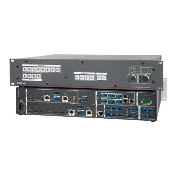
- Page 1 Setup Guide Matrix Switchers DTP CrossPoint 84 Scaling Presentation Matrix Switchers with DTP Extension IMPORTANT: IMPORTANT: Refer to www.extron.com for the complete user guide, installation instructions, and specifications before connecting the product to the power source. 68-2349-50 Rev. E 01 20...
- Page 2 Safety Instructions...
- Page 3 All trademarks mentioned in this guide are the properties of their respective owners. The following registered trademarks, registered service marks, and trademarks are the property of RGB Systems, Inc. or Extron Electronics (see the current list of trademarks on Terms of Use page at www.extron.com):...
- Page 4 FCC Class A Notice This equipment has been tested and found to comply with the limits for a Class A digital device, pursuant to part 15 of the FCC rules. The Class A limits provide reasonable protection against harmful interference when the equipment is operated in a commercial environment. This equipment generates, uses, and can radiate radio frequency energy and, if not installed and used in accordance with the instruction manual, may cause harmful interference to radio communications.
- Page 5 Conventions Used in this Guide Notifications ATTENTION: • Risk of property damage. • Risque de dommages matériels. NOTE: note draws attention to important information. Software Commands Commands are written in the fonts shown here: ^AR Merge Scene,,Op1 scene 1,1 ^B 51 ^W^C [01] R 0004 00300 00400 00800 00600 [02] 35 [17] [03] E X! *X1&* X2)* X2#* X2! NOTE:...
-
Page 7: Table Of Contents
Setting the Front Panel Locks (Executive Modes) ..... 17 Selecting Lock Mode 2 or Toggling Between Mode 2 and Mode 0 ......17 Selecting Lock Mode 2 or Toggling Between Mode 2 and Mode 1 ......18 DTP CrossPoint 84 • Contents vii... - Page 8 DTP CrossPoint 84 • Contents...
-
Page 9: Introduction
DTP CrossPoint 84 IPCP SA — Includes a stereo audio amplifier and a built-in Extron IPCP Pro 350 control processor DTP CrossPoint 84 IPCP MA 70 — Includes a 70 V mono audio • amplifier and a built-in Extron IPCP Pro 350 control processor... - Page 10 The matrix switcher can be remotely controlled via an Ethernet LAN port, a serial port, or a USB port connection using either the Extron Product Configuration Software, DSP Configurator software, or the Simple Instruction Set (SIS). DTP CrossPoint 84 • Introduction...
-
Page 11: Dtp Input And Output Signals
Depending on the technology of the transmitting or receiving device, DTP 330 or DTP 230, the TP inputs and outputs can travel up to 330 feet (100 meters) or 230 feet (70 meters) without a loss of signal integrity. DTP CrossPoint 84 • Introduction... -
Page 12: Installation
LINK OVER TP MIC/LINE RS-232 Tx Rx Tx Rx 50-60 Hz Figure 2. DTP CrossPoint 84 Switcher Rear Panel ATTENTION: • Remove system power before making all connections. • Débranchez l’alimentation du système avant de faire n’importe quelle connexion. NOTES: •... -
Page 13: Video Inputs And Outputs
TP connector. Failure to comply can damage the endpoint. Positionnez le sélecteur AVANT de connecter • l’appareil approprié au connecteur TP. Ne pas respecter cette procédure pourrait endommager le point de connexion. DTP CrossPoint 84 • Installation... -
Page 14: Audio Inputs And Outputs
Amp Output 1 (SA [stereo] model) — Plug passive, 4-ohm or 8-ohm speakers to this 5 mm 4-pole captive screw connector to receive the amplified audio from output 1. CLASS 2 WIRING DTP CrossPoint 84 • Installation... -
Page 15: Serial And Ir Insertion Connections
LAN (Ethernet) port (non-IPCP model) — If desired, connect a network WAN or LAN hub, a control system, or a computer to the TP connectors Ethernet RJ-45 port (see on page 10 to wire the connector). NOTE The factory default IP address is 192.168.254.254. DTP CrossPoint 84 • Installation... -
Page 16: Switcher Reset
For different reset levels, press and hold the recessed button while the switcher is running or while you power up the switcher. See the DTP CrossPoint 84 Series User Guide, available at www.extron.com. Power Power connector — Plug the switcher into a grounded AC source. -
Page 17: Additional Connector Information
Loosely place the included tie wrap around the HDMI connector and the LockIt lacing bracket as shown. While holding the connector securely against the lacing bracket, use pliers or similar tool to tighten the tie wrap, then remove any excess length. DTP CrossPoint 84 • Installation... - Page 18 • Crossover cable (see figure 7) — • LAN ports — UTP or STP for direct connection between the DTP CrossPoint 84 matrix switcher and a connected computer. Straight-through Cable Crossover Cable DTP I/O Ports, Expansion Port, and LAN Ports...
- Page 19 Power over Ethernet port; equipment damage can occur. • Connectez ce port au port d’expansion sur un processeur DMP d’Extron compatible. Ne connectez PAS ce port à un port LAN ou d’alimentation via Ethernet ; le matériel pourrait être endommagé. DTP CrossPoint 84 • Installation...
- Page 20 Do not comb the cable for the first 20 meters, where cables are • straightened, aligned, and secured in tight bundles. Loosely place cables and limit the use of tie wraps or hook and • loop fasteners. • Separate tw isted pair cables from AC power cables. DTP CrossPoint 84 • Installation...
- Page 21 If the stripped section of wire is shorter than 3/16 inch, wires can be easily pulled out even if tightly fastened. • Do not tin the power supply leads. Tinned wires are not as secure in the connector and could be pulled out. DTP CrossPoint 84 • Installation...
-
Page 22: Front Panel
A front panel Configuration port connection and a rear panel Remote port connection can both be active at the same time. If commands are sent simultaneously to both, the command that reaches the processor first is handled first. DTP CrossPoint 84 • Installation... -
Page 23: Front Panel Operations
Amber indicates video and audio tie. Green indicates video only tie. Red indicates audio only tie. Green indicates the need ENTER to confirm the change. Press and release the Enter button. All button indicators turn off. DTP CrossPoint 84 • Front Panel Operations... -
Page 24: Recalling A Preset
Rotate the applicable knob clockwise to increase the program volume or mic volume. Rotate the knob counterclockwise to decrease volume. The LED ladder indicates the approximate volume; the more LEDs are lit, the higher the volume. DTP CrossPoint 84 • Front Panel Operations... -
Page 25: Setting The Front Panel Locks (Executive Modes)
PRESET VIEW VIDEO AUDIO VIDEO AUDIO Press and hold for 2 seconds. Lock mode 0 CONTROL CONTROL ENTER PRESET VIEW VIDEO AUDIO ENTER PRESET VIEW VIDEO AUDIO Press and hold for 2 seconds. DTP CrossPoint 84 • Front Panel Operations... -
Page 26: Selecting Lock Mode 2 Or Toggling Between Mode 2 And Mode 1
Audio button simultaneously for approximately 2 seconds. Lock mode 1 Lock mode 2 CONTROL VIDEO AUDIO VIDEO AUDIO VIDEO AUDIO ENTER PRESET VIEW VIDEO AUDIO Press and hold Press and hold for 2 seconds. for 2 seconds. DTP CrossPoint 84 • Front Panel Operations... -
Page 27: Remote Control
If the switcher is password-protected, a password prompt • appears. If necessary, enter the appropriate password. If the password is accepted, the switcher responds with Login User or Login Administrator. If the password is not accepted, the Password prompt reappears. DTP CrossPoint 84 • Remote Control... -
Page 28: Number Of Connections
NOTE: The tables that begin on the next page are a partial list of SIS commands. For a complete listing, see the DTP CrossPoint 84 Series User Guide. Common SIS Command Symbols The following symbols are used throughout the command and response table, which starts on the next page: •... -
Page 29: Sis Command And Response Table For Matrix Switcher Commands
SIS Command and Response Table for Matrix Switcher Commands Command SIS Command Response Additional Description (Host to Unit) (Unit to Host) Create ties NOTES: • Commands can be entered back-to-back in a string, with no spaces. For example: 1*1!02*02$03*03%4*4$ • The matrix switchers support 1- and 2-digit numeric entries ( 1*1! 02*02%... - Page 30 Command SIS Command Response Additional Description (Host to Unit) (Unit to Host) Video mutes (continued) Read video mute Global video mute Vmt1 Mute all video outputs. Global video unmute Vmt0 Unmute all video outputs. HDCP status View input HDCP status HDCP View HDCP status of all inputs I*HDCP...
- Page 31 Command SIS Command Response Additional Description (Host to Unit) (Unit to Host) List Digital Sync Validation Processing (DSVP) List sync of all inputs Eight s; each is the signal status of an input, starting from input 1. Example: no input detected input detected 0 0 0 1 1 1 0 0 Response Status:...
- Page 32 (Unit to Host) Group master level (volume and mute) NOTES: • The DTP CrossPoint 84 has 16 configurable group masters. • By factory default, group 1 controls the program volume and group 2 controls the mic volume. • Other group masters (such as mutes) must be preset (have already been created) in the DSP Configurator program to be available as for SIS commands.
- Page 33 Command SIS Command Response Additional Description (Host to Unit) (Unit to Host) Recall a preset X1#] Recall a preset Recall preset View video and audio mutes View output mutes Each response is the mute status of an output, starting from output 1. Example: 0221 Output 1 is unmuted.
-
Page 34: Installing And Starting The Control Programs
DSP functions of the switchers and to save presets. It also provides some limited control of the non-DSP functions of the switcher. See the DTP Crosspoint 84 User Guide and the program Help file for more information. Run either program from a PC connected to an... - Page 35 ) (Product Configuration Software shown). 1 1 1 1 1 1 1 1 Download the Software Figure 12. Follow the on-screen instructions. The installation program creates the necessary directories and folders and installs the programs. DTP CrossPoint 84 • Remote Control...
-
Page 36: Starting The Product Configuration Software
) and click Connect ( NOTE: The default IP address is 192.168.254.254 . The Product Configuration Software opens. Operate the program as described in the DTP CrossPoint 84 User Guide, available at www.extron.com, and the built-in Help file. DTP CrossPoint 84 • Remote Control... -
Page 37: Starting The Dsp Configurator Program
Extron recommends connection via an Ethernet LAN port for the DSP Configurator program. Start the DSP Configurator program, as follows: Click Start > Programs > Extron Electronics > DSP Configurator > DSP Configurator. The DSP Configurator startup screen displays (see figure 14 on page 29). - Page 38 In Emulate mode, changes and settings are stored in the PC and not sent to the switcher until you select Live mode and "push' the settings to the switcher. See the DTP CrossPoint 84 Switcher User Guide . DTP CrossPoint 84 • Remote Control...
-
Page 39: Accessing The Html Pages
... b ox, and then click OK. • For details on operating the switcher via HTML pages, see the "HTML Operation" section in the DTP CrossPoint 84 User Guide. Start the web browser program. DTP CrossPoint 84 • Remote Control... - Page 40 Enter the appropriate administrator or user password in the Password field and click OK. figure 18 The switcher downloads the HTML start-up page (see page 33). The switcher is ready for operation via HTML remote control. DTP CrossPoint 84 • Remote Control...
- Page 41 Figure 18. HTML Startup Page DTP CrossPoint 84 • Remote Control...
- Page 42 DTP CrossPoint 84 • Remote Control...
- Page 43 In no event will Extron Electronics be liable for direct, indirect, or consequential damages resulting from any defect in this product even if Extron Electronics has been advised of such damage.
- Page 44 Worldwide Headquarters: Extron USA West, 1025 E. Ball Road, Anaheim, CA 92805, 800.633.9876...