Table of Contents
Advertisement
Quick Links
TECHNICAL MANUAL
Of
Intel Q87 Express Chipset
Based Mini-ITX M/B
NO. G03-NF9QU-F
Revision: 5.0
Release date: October 1, 2019
Trademark:
* Specifications and Information contained in this documentation are furnished for information use only, and are
subject to change at any time without notice, and should not be construed as a commitment by manufacturer.
Advertisement
Table of Contents

Related Manuals for JETWAY JNF9QU-Q87


Summary of Contents for JETWAY JNF9QU-Q87
- Page 1 TECHNICAL MANUAL Intel Q87 Express Chipset Based Mini-ITX M/B NO. G03-NF9QU-F Revision: 5.0 Release date: October 1, 2019 Trademark: * Specifications and Information contained in this documentation are furnished for information use only, and are subject to change at any time without notice, and should not be construed as a commitment by manufacturer.
- Page 2 Environmental Protection Announcement Do not dispose this electronic device into the trash while discarding. To minimize pollution and ensure environment protection of mother earth, please recycle.
-
Page 3: Table Of Contents
TABLE OF CONTENT ENVIRONMENTAL SAFETY INSTRUCTION ................iii USER’S NOTICE ........................iv MANUAL REVISION INFORMATION ..................iv ITEM CHECKLIST ........................iv CHAPTER 1 INTRODUCTION OF THE MOTHERBOARD FEATURE OF MOTHERBOARD ................1 SPECIFICATION ......................2 LAYOUT DIAGRAM ....................3 CHAPTER 2 HARDWARE INSTALLATION JUMPER SETTING ..................... -
Page 4: Environmental Safety Instruction
Environmental Safety Instruction Avoid the dusty, humidity and temperature extremes. Do not place the product in any area where it may become wet. 0 to 60 centigrade is the suitable temperature. (The figure comes from the request of the main chipset) ... -
Page 5: User's Notice
USER’S NOTICE COPYRIGHT OF THIS MANUAL BELONGS TO THE MANUFACTURER. NO PART OF THIS MANUAL, INCLUDING THE PRODUCTS AND SOFTWARE DESCRIBED IN IT MAY BE REPRODUCED, TRANSMITTED OR TRANSLATED INTO ANY LANGUAGE IN ANY FORM OR BY ANY MEANS WITHOUT WRITTEN PERMISSION OF THE MANUFACTURER. -
Page 6: Chapter 1 Introduction Of The Motherboard
Chapter 1 Introduction of the Motherboard Feature of Motherboard ® Intel Q87 express chipset ® ® Support Intel LGA 1150 Socket Intel Core™ i3, i5, i7 & Pentium Processors in LAG1150 Package (Max. 65W TDP) Support 2* DDRIII SO-DIMM 1333/1600 MHz up to 16GB and dual channel function ®... -
Page 7: Specification
1-2 Specification Spec Description Mini-ITX form factor; 6 layers ; PCB size: 17.0x17.0cm Design ® Intel Q87 Express Chipset Chipset ® Supports Intel Core™ i7, Core™ i5, Core™ i3 series, ® CPU Socket Pentium processor in LAG1150 Package (Max. -
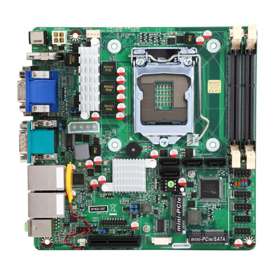
Page 8: Layout Diagram
Internal I/O Connectors& Headers: 1 *4-pin 9V~24V internal power connector 4* SATAIII connector 1* 4-pin SATA hard disk power connector 1* Front panel audio header 1* HDMI_SPDIF out header 2* LAN port activity indicator LED header ... - Page 9 Motherboard Internal Diagram 9V~24V Internal Power Connector Intel LGA 1150 SYSFAN1Header CPUFAN Header CPU Socket 9V~24V DC Power-in Connector HDMI Port DDRIII SODIMM Slot x 2 VGA Port over (DDRIII 1333/1600) DVI-D Port KB &MS Heade SATAIII Ports Speaker & Serial Ports Power LED Header Hard Disk...
- Page 10 Motherboard Jumper Positions AT-MODE COPEN JBAT...
- Page 11 Jumper Jumper Name Description COM1 Port Pin9 Function Select 4-pin Block COM2 Port Pin9 Function Select 4-pin Block MPE Slot VCC3.3V /3VSB Select 3-pin Block MMPE Slot VCC3.3V /3VSB Select 3-pin Block JBAT CMOS RAM Clear Function Setting 3-pin Block Security Measure Function Select 2-pin Block AT-MODE...
- Page 12 Headers Header Name Description FP_AUDIO Front Panel Audio Header 9-pin Block SPDIFOUT HDMI_SPDIF Out Header 2-pin Block LAN1LED/LAN2LED LAN LED Header 2-pin Block COM3/COM4 RS232 Serial Port Header X2 9-pin Block GPIO GPIO Header 10-pin Block PS2KBMS PS2 KB & MS Header 6-pin Block SMBUS SM BUS Header...
-
Page 13: Chapter 2 Hardware Installation
Chapter 2 Hardware Installation 2-1 Jumper Setting (1) JP1 (4-pin): COM1 Port Pin9 Function Select JP1→COM1 Port 2 4 6 2 4 6 1 3 5 1 3 5 2-4 Closed: 3-4 Closed: 4-6 Closed: RI=RS232; RI= 5V; RI= 12V. (2) JP2 (4-pin): COM4 Header Pin9 Function Select JP2→COM4 Port 2-4 Closed:... - Page 14 (3) JP5 (3-pin): MPE Slot VCC3.3V/ 3VSB Select JP5→MPE Slot(Half-size Mini-PCIE Slot) 1-2 Closed: MPE Slot VCC= 3.3V; 2-3 Closed: MPE Slot VCC= 3VSB. (4) JP7 (3-pin): MMPE Slot VCC3.3V/ 3VSB Select JP7→MMPE Slot(Full-size Mini-PCIE/MSATA Slot) 1-2 Closed: MMPE Slot VCC= 3.3V; 2-3 Closed: MMPE Slot VCC= 3VSB.
- Page 15 (5) JBAT (3-pin): Clear CMOS Function Settings JBAT→Clear COMS 1-2 Closed: Normal; 2-3 Closed:Clear CMOS. (6)JP4 (2-pin): Security Measure Function Select 1-2 Open:Enable Security Measures in the Flash Descriptor(Default); 1-2 Closed: Disable Security Measures in the Flash Descriptor(Override). (7)AT_MODE (2-pin): AT Mode Function Select Pin 1-2 closed: AT_MODE function is enabled.
- Page 16 AT-MODE 1-2 Open: Normal; 1-2 Closed: AT Mode Selected. (8)COPEN (2-pin): Case Open Message Display Function Select Pin 1-2 Closed: When Case open function pin short to GND, the Case open function was detected. When Used, needs to enter BIOS and enable ‘Case Open Detect’ function.
-
Page 17: Connectors And Headers
Connectors and Headers 2-2-1 Connectors (1) Rear Panel Connectors Serial Port RJ-45 LAN Ports VGA Port (COM1) HDMI Port Line-OUT 9V~24V MIC-IN DC Power-in Connector Serial Port DVI-D Port USB 3.0 Ports (COM2) (2) COM1 (9-pin Block): RS232/422/485 Serial Port COM1 port can function as RS232/422/485 port. - Page 18 (3) DCPWRIN (4-pin block): 9V~24V Internal Power Connector Pin No. Definition +9V~+24V +9V~+24V (4) PWOUT (4-pin block): SATA Hard Disk Power Connector Pin No. Definition +12V...
-
Page 19: Headers
(5) SATA1/2/3/4(7-pin block): SATAIII Port connector These connectors are high-speed SATAIII ports that support 6 GB/s transfer rate. Pin No. Definition 2-2-2 Headers (1) FP_AUDIO (9-pin): Line-Out, MIC-In Header This header connects to Front Panel Line-out, MIC-In connector with cable. FP_AUDIO Pin 1 Line-Out, M I C Header... - Page 20 (2) SPDIFOUT (2-pin): HDMI-SPDIF Out Header Pin1 HDMI_SPDIF Header (3) LAN1LED/LAN2LED (2-pin): RJ-45 LAN LED Activity Headers LED+ Pin1 LED- LAN1LED Pin1 LAN2LED...
- Page 21 (4) COM3/COM4 (9-Pin): RS232 Serial Port Headers Pin6 Pin1 Pin5 Serial Port Header (5) GPIO (10-pin): GPIO Header Pin 1...
- Page 22 (6) PS2KBMS (6-pin): PS/2 Keyboard & Mouse Header Pin1 (7)SMBUS (4-pin): SMBUS Header SMBUS_DATA SMBUS_CLK Pin1 SMBUS...
- Page 23 (8) USB2/USB3 (9-pin): USB 2.0 Port Header Pin 1 (9) USB1 (19-pin): USB 3.0 Port Header Pin 1...
- Page 24 (10) SPK-LED (7-pin): Speaker Header & PWR LED Header SPK- PWRLED- PWRLED- SPK+ PWRLED+ Pin 1 (11) FP (9-pin): Front Panel Header Pin 1...
- Page 25 (12) CPUFAN1/SYSFAN1/SYSFAN2 (4-pin): FAN Headers Pin1 CPUFAN/SYSFAN1 Pin1 +12V Fan Power Fan Speed Control SYSFAN2...
-
Page 26: Chapter 3 Introducing Bios
Chapter 3 Introducing BIOS Notice! The BIOS options in this manual are for reference only. Different configurations may lead to difference in BIOS screen and BIOS screens in manuals are usually the first BIOS version when the board is released and may be different from your purchased motherboard. Users are welcome to download the latest BIOS version form our official website. -
Page 27: Bios Menu Screen
BIOS Menu Screen The following diagram show a general BIOS menu screen: Menu Bar General Help Items Menu Items Current Setting Value Function Keys BIOS Menu Screen Function Keys In the above BIOS Setup main menu of, you can see several options. We will explain these options step by step in the following pages of this chapter, but let us first see a short description of the function keys you may use here: ... -
Page 28: Getting Help
Press <+>/<–> keys when you want to modify the BIOS parameters for the active option. [F1]: General help. [F2]: Previous value. [F3]: Optimized defaults. [F4]: Save & Exit. Press <Esc> to quit the BIOS Setup. Getting Help Main Menu The on-line description of the highlighted setup function is displayed at the top right... -
Page 29: Main Menu
Main Menu Main menu screen includes some basic system information. Highlight the item and then use the <+> or <-> and numerical keyboard keys to select the value you want in each item. System Date Set the date. Please use [Tab] to switch between data elements. System Time Set the time. -
Page 30: Advanced Menu
3-7 Advanced Menu ERP Function The optional settings: [Auto]; [Disabled]. This item should be set as [Disabled] if you wish to have all active wake-up functions. ACPI Settings Press [Enter] to make settings for the following sub-item: ACPI Settings ACPI Sleep State Use this item to select the highest ACPI sleep state the system will enter when the suspend button is pressed. - Page 31 Use this item to enable or disable system wake on alarm event. When set as [Enabled], system will wake on the hour/min/sec specified. PS2 KB/MS Wakeup Use this item to enable or disable PS2 KB/MS wakeup from S3/S4/S5 state. *This item will only show when ‘EUP Support’ is set as [Disabled]. USB S3/S4 Wakeup Use this item to enable or disable USB S3/S4 wakeup.
- Page 32 [Disabled]: for other OS (OS optimized not for Hyper-Threading Technology). Active Processor Cores Use this item to select number of cores to enable in each processor package. Limit CPUID Maximum The optional settings: [Disabled]; [Enabled]. This item should be set as [Disabled] for Windows XP. Execute Disable Bit The optional settings: [Disabled];...
- Page 33 The optional settings: [Disabled]; [Enabled]. SATA Mode Selection The optional settings are: [IDE]; [AHCI]; [RAID]. *When set as [IDE] or [RAID], user can make further settings in ’IDE Legacy/Native Mode Selection’. IDE Legacy/Native Mode Selection The optional settings are: [Native]; [Legacy]. *When set as [AHCI] or [RAID], user can make further settings in the following items: Aggressive LPM Support...
- Page 34 (immediately) to 120 minutes. Active Page Threshold Support Use this item to enable or disable support for RST with small partition. Hybrid Hard Disk Support Use this item to enable or disable Hybrid Hard Disk Support. RapidStart Display Save/Restore Use this function to enable or disable RapidStart Display Save/Restore function. ...
- Page 35 Disable ME Use this item to set ME to soft Temporary Disabled function. Use this item to enable or disable Alert Specification Format. Active Remote Assistance Process Use this item to enable or disable Trigger CIRA boot function. USB Configure Use this item to enable or disable USB configure function.
- Page 36 This is a workaround for OSes without EHCI hand-off support. The EHCI ownership change should be claimed by EHCI driver. The optional settings are: [Disabled]; [Enabled]. USB Mass Storage Driver Support The optional settings are: [Disabled]; [Enabled]. USB hardware delay and time-out: USB Transfer time-out Use this item to set the time-out value for control, bulk, and interrupt transfers.
- Page 37 The optional settings are: [RS232/RS422/RS485=250kbps]; [RS232=1Mbps, RS422/RS485=10Mbps]. Serial Port FIF0 Mode The optional settings are: [16-Byte FIF0]; [32-Byte FIF0]; [64-Byte FIF0]; [128-Byte FIF0]. Serial Port 2 Configuration/Serial Port 3 Configuration/Serial Port 4 Configuration/Serial Port 5 Configuration Press [Enter] to make settings for the following items: Serial Port Use this item to enable or disable serial port (COM).
- Page 38 Use this item to select system shutdown temperature. The optional settings are: [Disabled]; [70 C/156 F]; [75 C/164 F]; [80 C/172 C/180 F]; [90 C/188 SmartFan Configuration Press [Enter] to make settings for SmartFan Configuration: SmartFan Configuration CPUFAN / SYSFAN1/ SYSFAN2 Smart Mode The optional settings are: [Disabled];...
-
Page 39: Chipset Menu
3-8 Chipset Menu PCH-IO Configuration Press [Enter] to make settings for the following sub-items: USB Configuration Press [Enter] to further setting USB device configuration. USB Configuration XHCI Mode Use this item to select mode of operation for XHCI controller. The optional settings are: [Smart Auto];... - Page 40 *When set as [Manual], the following sub-items shall appear: Route USB 2.0 pins to which HC? The optional settings are: [Route Per-Pin]; [Route all Pins to EHCI]; [Route all Pins to XHCI]. Enable USB 3.0 pins The optional settings are: [Select Per-Pin]; [Disable all Pins]; [Enable all Pins]. Azalia Use this function to control the detection of the Azalia device.
- Page 41 Graphics Configuration Press [Enter] to make further settings for Graphics Configuration. Graphics Configuration Primary IGFX Boot Display Use this item to select the video device which will be activated during POST. This has no effect if external graphics present. Secondary boot display selection will appear based on your selection.
-
Page 42: Boot Menu
Enable PCIE1 The optional settings are: [Disabled]; [Enabled]; [Auto]. PCIE1- ASPM Use this item to control ASPM support for the PEG device. This has no effect if PEG is not the currently active device. The optional settings are: [Disabled]; [Auto]; [ASPM L0s]; [ASPM L1]; [ASPM L0sL1]. - Page 43 Boot Configuration Setup Prompt Timeout Use this item to set number of seconds to wait for setup activation key. Bootup Numlock State Use this item to select keyboard numlock state. The optional settings are: [On]; [Off]. Quiet Boot The optional settings are: [Disabled]; [Enabled]. Boot Option Priorities ►...
-
Page 44: Security Menu
3-10 Security Menu Security menu allow users to change administrator password and user password settings. -
Page 45: Save & Exit Menu
3-11 Save & Exit Menu Save Changes and Reset This item allows user to reset the system after saving the changes. Discard Changes and Reset This item allows user to reset the system without saving any changes. Restore Defaults Use this item to restore /load default values for all the setup options. Save as User Defaults Use this item to save the changes done so far as user defaults.