Table of Contents
Advertisement
Quick Links
TECHNICAL MANUAL
Of
Intel Cedar Trail-D & NM10 Chipset
Based
Mini-ITX M/B for ATOM Processor
NO. G03-NC9N-F
Revision: 1.0
Release date: September 14, 2012
Trademark:
* Specifications and Information contained in this documentation are furnished for information use only, and are
subject to change at any time without notice, and should not be construed as a commitment by manufacturer.
Advertisement
Table of Contents

Related Manuals for JETWAY JNC9NDL-2550


Summary of Contents for JETWAY JNC9NDL-2550
- Page 1 TECHNICAL MANUAL Intel Cedar Trail-D & NM10 Chipset Based Mini-ITX M/B for ATOM Processor NO. G03-NC9N-F Revision: 1.0 Release date: September 14, 2012 Trademark: * Specifications and Information contained in this documentation are furnished for information use only, and are subject to change at any time without notice, and should not be construed as a commitment by manufacturer.
- Page 2 Environmental Protection Announcement Do not dispose this electronic device into the trash while discarding. To minimize pollution and ensure environment protection of mother earth, please recycle.
-
Page 3: Table Of Contents
TABLE OF CONTENT ENVIRONMENTAL SAFETY INSTRUCTION................iii USER’S NOTICE ........................iv MANUAL REVISION INFORMATION ..................iv ITEM CHECKLIST ........................iv CHAPTER 1 INTRODUCTION OF THE MOTHERBOARD FEATURE OF MOTHERBOARD................1 SPECIFICATION ......................2 LAYOUT DIAGRAM....................3 CHAPTER 2 HARDWARE INSTALLATION JUMPER SETTING ..................... -
Page 4: Environmental Safety Instruction
Environmental Safety Instruction Avoid the dusty, humidity and temperature extremes. Do not place the product in any area where it may become wet. 0 to 60 centigrade is the suitable temperature. (The figure comes from the request of the main chipset) Generally speaking, dramatic changes in temperature may lead to contact malfunction and crackles due to constant thermal expansion and contraction from the welding spots’... -
Page 5: User's Notice
USER’S NOTICE COPYRIGHT OF THIS MANUAL BELONGS TO THE MANUFACTURER. NO PART OF THIS MANUAL, INCLUDING THE PRODUCTS AND SOFTWARE DESCRIBED IN IT MAY BE REPRODUCED, TRANSMITTED OR TRANSLATED INTO ANY LANGUAGE IN ANY FORM OR BY ANY MEANS WITHOUT WRITTEN PERMISSION OF THE MANUFACTURER. -
Page 6: Chapter 1 Introduction Of The Motherboard Feature Of Motherboard
Chapter 1 Introduction of the Motherboard Feature of Motherboard Intel Cedar Trail-D and NM10 chipset, with low power consumption never denies high performance Support two DDRIII 800/1066MHz SO-DIMM up to 4GB Support two Serial ATAII (3Gb/s) Devices Onboard dual Realtek RTL 8111EVL Gigabit Ethernet LAN chip Integrated ALC662-GR 6-channel HD audio CODEC Support USB 2.0 data transport demands Support PCI slot and Mini-PCIE slot... -
Page 7: Specification
Specification Spec Description Mini-ITX form factor; PCB size: 17.0x17.0cm Design ® Intel NM10 Express chipset Chipset Intel Cedar Trail-D Processor Embedded CPU DDRIII SO-DIMM slot x 2 Support two DDRIII 800/1066 MHz SO-DIMM with memory Memory Slot capacity expandable to 4GB 32-bit PCI slot x 1 Expansion Slot Mini-PCIE slot x1... -
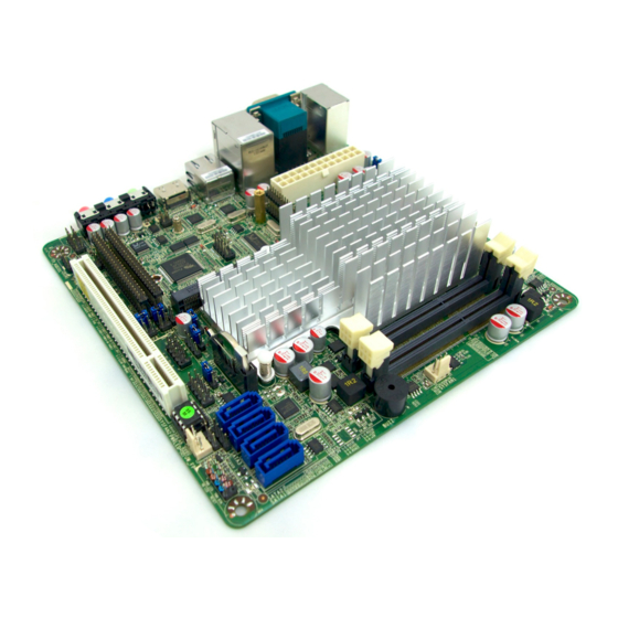
Page 8: Layout Diagram
Speaker header x1 Front panel LANLED header x2 24- bit single channel LVDS header x1 LVDS inverter x1 1-3 Layout Diagram Rear IO Diagram RJ-45 LAN Ports Serial Port VGA Port Line-IN/ Optical SPDIF OUT Line-OUT 12V DC MIC-IN Power-in Jack USB 2.0 Ports HDMI Port Serial Port... - Page 9 Motherboard Internal Diagram SATA Power Out Connector ATX12V Power Connector SFAN2 Header CPUFAN1 Header 12V DC Power-in Jack TX-RX COM Header SODIMM1 Slot Serial Ports Inverter SODIMM2 Slot LVDS Header Intel KBMS VGA Port over Header HDMI Port SFAN1Header Intel NM10 Chipset GPIO Header RJ-45 LAN Port over USB 2.0 Headers...
- Page 10 Motherboard Jumper Position CASE_OPEN JBAT1...
- Page 11 Jumper Jumper Name Description JBAT1 CMOS RAM Clear Function Setting 3-Pin Block UL1/UL2 USB Ports Power On Function Select 3-Pin Block LVDS PVCC 5V/3.3V Select 3-Pin Block INVERTER VCC 12V/5V Select 3-Pin Block USB 1/2 Header Power On Function Select 3-Pin Block COM1 Port Pin9 Function Select 6-Pin Block...
- Page 12 Headers Header Name Description AUDIO2 Front Panel Audio Header 9-pin block USB1 USB 2.0 Header 9-pin Block USB2 USB 2.0 Header 4-pin Block SM_BUS SM Bus Header 4-pin Block KBMS PS2 Keyboard & Mouse Header 6-pin Block GPIO1 GPIO Header 10-pin Block COM3/4/5/6 Serial Port Header x4...
-
Page 13: Jumper Setting
Chapter 2 Hardware Installation 2-1 Jumper Setting (1) JBAT1 (3-pin): Clear CMOS JBAT1 JBAT1 1-2 closed: Normal; 2-3 closed : Clear CMOS (2) JP1 (3-pin): UL1/UL2 USB Ports Power on Function Select 1-2 closed : UL1/UL2 USB Ports Power on Function Disabled(default); 2-3 closed: UL1/UL2 USB Ports Power on Function Enabled... - Page 14 (3) JP2 (3-pin): LVDS PVCC 5V/3.3V Select 1-2 closed: LVDS PVCC=5V(default); 2-3 closed : LVDS PVCC=3.3V (4) JP4 (3-pin): INVERTER VCC 12V/5V Select 1-2 closed:Inverter1 VCC=12V (default); 2-3 closed:Inverter1 VCC=5V...
- Page 15 (5) JP5 (3-pin): USB 1/2 Header Power On Function Select 1-2 closed : USB 2/3 Header Power on Disabled(default); 2-3 closed: USB 2/3 Header Power on Enabled (6) JP7 (6-pin): COM1 Port Pin9 Function Select 1-2 closed: RS232; 3-4 closed : +12V; 5-6 closed : +5V...
- Page 16 (7) JP8 (6-pin): COM2 Header RS232/485/422 Function Select 3-4 closed : RS485; 5-6 closed : RS422 1-2 closed: RS232; (8) JP9 (3-pin): Mini PCI-E Power 3.3V/ 3VSB Function Select 1-2 closed:MINI PCI-E Power= VCC 3.3V; 2-3 closed:MINI PCI-E Power=3VSB...
-
Page 17: Connectors And Headers
(9)CASE_OPEN(2-pin): Case Open Message Display Function Select Pin 1-2 shorted: Case open display function enabled. Use needs to enter BIOS and enable ‘Case Open Detect’ function. In this case if you case is removed, next time when you restart your computer a message will be displayed onscreen to inform you of this. - Page 18 (2) ATX12V1 (4-pin block): ATX12V Type Power Connector Pin1 Pin No. Definition +12V +12V (3) PWR2 (4-pin): SATA Power Out Connector P in1 P in N o. De fin it io n +12 V G N D G N D VC C (4) SATA1/SATA2 (7-pin block): SATAII Port connector These connectors are high-speed SATAII ports that support 3 GB/s transfer...
-
Page 19: Headers
Pin No. Definition 2-2-2 Headers (1) AUDIO2 (9-pin): Front Panel Audio Header This header connects to front panel Line-out, MIC-In connector with cable. Pin 1 Line-Out, MIC Header... - Page 20 (2) USB1 (9-pin): USB 2.0 Port Header (3) USB2 (4-pin): USB 2.0 Port Header +DATA -DATA Pin1...
- Page 21 (4)SM_BUS (4-pin): SM BUS Header Pin 1 (5) KBMS (6-pin): PS/2 Keyboard & Mouse Header Pin1...
- Page 22 (6) GPIO1 (10-pin): GPIO Header Pin 1 (7) COM3/COM4/COM5/COM6 (9-pin): Serial Port Headers Pin1...
- Page 23 (8) TX-RX (4-pin): RS422/485 Header Pin 1 (9) SPEAK1 (4-pin): Speaker Header This 4-pin header connects to the case-mounted speaker. See the figure below. (10) PWR LED1 (3-pin): Power LED Header The Power LED is light on while the system power is on. Connect the Power LED from the system case to this pin header.
- Page 24 (11) JW-FP1 (9-pin): Front Panel Header Pin 1 (12) LANLED1/LANLED2 (2-pin): LANLED Headers Pin1 LED+ LED-...
- Page 25 (13) CPUFAN1, SFAN1, SFAN2 (3-pin): FAN Headers Pin1: GND Pin2: +12V fan power Pin3: Fan Speed CPUFAN1/SFAN2 Pin1 SFAN1 Pin1 (14) INVERTER (8-pin): LVDS Inverter Connector Pin No. Definition Backlight Enable Backlight Duty PVCC PVCC Backlight+ SW Pin 1 Backlight- SW INVERTER...
- Page 26 (15) LVDS1 (35-pin): 24-bit single channel LVDS Header Pin 2 Pin 1 Pin NO. Pin Define Pin NO. Pin Define Pin 1 Pin 2 Pin 3 Pin 4 Pin 5 Pin 6 Pin 7 Pin 8 Pin 9 Pin 10 Pin 11 LVDS_DDC_DATA Pin 12...
-
Page 27: Chapter 3 Introducing Bios
Chapter 3 Introducing BIOS Notice! The BIOS options in this manual are for reference only. Different configurations may lead to difference in BIOS screen and BIOS screens in manuals are usually the first BIOS version when the board is released and may be different from your purchased motherboard. Users are welcome to download the latest BIOS version form our official website. -
Page 28: Bios Menu Screen
BIOS Menu Screen The following diagram show a general BIOS menu screen: Menu Bar General Help Items Menu Items Current Setting Value Function Keys Instruction Function Keys In the above BIOS Setup main menu, you can see several options. We will explain these options step by step in the following pages of this chapter, but let us first see a short description of the function keys you may use here: Press←→... -
Page 29: Getting Help
Press <Enter> to select. Press <+>/<–> key when you want to modify the BIOS parameters for the active option. [F1]: Press to general help information. [F2]: Press to load previous value. [F3]: Press to load optimized defaults. [F4]: Save and Reset. Press <Esc>... -
Page 30: Main Menu
Main Menu Main menu screen includes some basic system information. Highlight the item and then use the <+> / <-> key or numerical keyboard keys to select the value you want in each item. System Date Set the date. Please use [TAB] to switch between data elements. System Time Set the time. -
Page 31: Advanced Menu
3-7 Advanced Menu Legacy OpROM Support: Launch External PxE OpROM/Launch LAN1 PXE OpROM//Launch LAN2 PXE OpROM Use this item to enable or disable boot option for legacy network devices. Launch Storage OpROM Use this item to enable or disable boot option for legacy mass storage devices with option ROM. - Page 32 Onboard LAN 2 Controller Use this item to enable or disable PCI Express root port 2. ERP Function Use this item to enable or disable ERP function for this board. This item should be set as [Disabled] if you wish to have active all wakeup function. ►...
- Page 33 Use this item to enable or disable system wake on alarm event. When set as [Enabled], system will wake on the hour/min/sec specified. PS2 KB/MS Wakeup Use this item to enable or disable PS2 KB/MS wakeup function. This function is only supported when ERP function is set as [Disabled].
- Page 34 EHCI Hand-off The optional settings are: [Disabled]; [Enabled]. USB hardware delays and time-outs: USB Transfer time-out Use this item to set the time-out value for control, bulk, and interrupt transfers. Device reset time-out Use this item to set USB mass storage device start unit command time-out. Device power-up delay Use this item to set maximum time the device will take before it properly reports itself to the host controller.
- Page 35 Change Settings Use this item to select an optimal setting for super IO device. Serial Port Mode Select The optional settings are: [RS232]; [RS422/RS485]. PS2 KB/MS Connect Use this item to set PS2 connect primary device. The optional settings are: [Keyboard First];...
- Page 36 ► Voltage Configuration DIMM Voltage The optional settings are: [Default]; [+50mV]; [+100mV]; [+150mV]. ► Watchdog Configuration WatchDog Timer Control Use this item to enable or disable WatchDog Timer Control. When set as [Enabled], the following sub-items shall appear: WatchDog Timer Val User can set a value in the range of 4 to 255.
-
Page 37: Chipset Menu
3-8 Chipset Menu ► Host Bridge Press [Enter], user can have a view of memory information and make settings for Intel IGD Configuration: LVDS Configuration IGFX-Boot Type Use this item to set the video device which will be activated during POST. This has no effect if external graphics presents. - Page 38 Backlight Control The optional settings are: [PWM Inverted]; [PWM Normal]. In the case IGFX-Boot Type is set as [LVDS]; [HDMI+LVDS]; or [CRT+LVDS], the following setting item shall appear: LCD Panel Type: The optional settings are: [1024 x 600]; [800 x 600]; [1024 x 768 18bit]; [1280 X 1024];[1366 x 768];...
-
Page 39: Boot Menu
Restore AC Power Loss Use this item to select AC power state when power is re-applied after a power failure (G3 State). The optional settings are: [Power Off]; [Power On]; [Last State]. 3-9 Boot Menu Setup Prompt Timeout Use this item to set number of seconds to wait for setup activation key. Bootup Numlock State Use this item to select keyboard numlock state. -
Page 40: Security Menu
Gate A20 Active The optional settings are: [Upon Request]; [Always]. Option ROM Message Use this item to set display mode for option ROM. The optional settings are: [Force BIOS]; [Keep Current]. Interrupt 19 Capture The optional settings are: [Enabled]; [Disabled]. 3-10 Security Menu Security menu allow users to change administrator password and user password settings. -
Page 41: Save & Exit Menu
3-11 Save & Exit Menu Save Changes and Reset This item allows user to reset the system after saving the changes. Discard Changes and Reset This item allows user to reset the system without saving any changes. Restore Defaults Use this item to restore /Load default values for all the setup options. Save as User Defaults Use this item to save the changes done so far as user defaults.