Table of Contents
Advertisement
Quick Links
Chapter 1
1-1 Preface.....................................................................................................1
1-2 Feature for BX2000/BX2100....................................................................1
1-2-1 Overview.......................................................................................1
1-2-2 Key Feature..................................................................................1
Chapter 2
2-1 Unpacking.................................................................................................3
2-2 BX2000/BX2100 Mainboard Diagram......................................................4
2-4 Installation Steps......................................................................................6
2-5 Jumper Settings........................................................................................6
2-6 System Memory (DRAM)..........................................................................7
2-7 Central Processing Unit (CPU).................................................................7
2-8 Expansion Cards......................................................................................8
2-9 External Connectors.................................................................................9
Chapter 3
3-1 STANDARD CMOS SETUP.....................................................................16
3-2 BIOS FEATURES SETUP........................................................................17
3-3 CHIPSET Features SETUP......................................................................18
3-4 POWER MANAGE MENT SETUP...........................................................19
3-5 PnP/PCI CONFIGURATION SETUP .......................................................22
3-6 LOAD OPTIMAL DEFAULTS...................................................................22
3-7 LOAD STANDARD DEFAULTS...............................................................23
3-8 INTEGRATED PERIPHERALS SETUP...................................................23
3-9 SUPERVISOR/USER PASSWORD.........................................................24
3-10 SAVE & EXIT SETUP..............................................................................24
3-11 EXIT WITHOUT SAVING........................................................................24
Chapter 4
4-1 Mainboard Driver Install in Win9X,WinNT................................................25
4-2 SOUND Card Driver QUICK Installation (Only for BX2100)....................26
Chapter 5
Quick Troubleshooting Guide...........................................................................44
Chapter 6
Frequently Asked Questions and Answers ......................................................45
TABLE OF CONTENT
....................................................................................3
...................................................................................15
i
Advertisement
Table of Contents

Related Manuals for JETWAY BX2000


Summary of Contents for JETWAY BX2000
-
Page 1: Table Of Contents
TABLE OF CONTENT Chapter 1 1-1 Preface.....................1 1-2 Feature for BX2000/BX2100..............1 1-2-1 Overview..................1 1-2-2 Key Feature..................1 Chapter 2 Hardware Installation ..................3 2-1 Unpacking....................3 2-2 BX2000/BX2100 Mainboard Diagram............4 2-3 Quick Reference for Jumpers, Connectors & Expansion Socket.....5 2-4 Installation Steps..................6 2-5 Jumper Settings..................6 2-6 System Memory (DRAM)................7... -
Page 2: Preface
Chapter 1 1-1 Preface Thank you for chosen BX2000/BX2100 mainboard. This is a multifunction mainboard with most flexibility you can find in today’s computer market. The mainboard integrates both Intel Pentium ® II / Pentium ® III & Celeron™(Slot 1 & Socket 370) processor interface into a compact PC/AT compatible system along with 3D Stereo Sound System audio chip. - Page 3 AGP, ISA, and PCI expansion Slots :Provide an AGP slot, one 16-bit ISA slot, and four 32-bit PCI master slots. Super Multi-I/O: Provides two high-Speed UART compatible serial ports and one parallel port with EPP and ECP capabilities. Two floppy drives of either 5.25” or 3.5” (1.44MB or 2.88MB) are also supported without an external card.
-
Page 4: Hardware Installation
Chapter 2 Hardware Installation 2-1 Unpacking This mainboard package should contain the following: BX2000/BX2100 mainboard USER’S MANUAL for mainboard Cable set for Ultra DMA 66 IDE x1, Floppy x1 CD for Drivers PACK The mainboard contains sensitive electronic components that can be easily damaged by electron-static, so the mainboard should be left in its original packing until it is installed. -
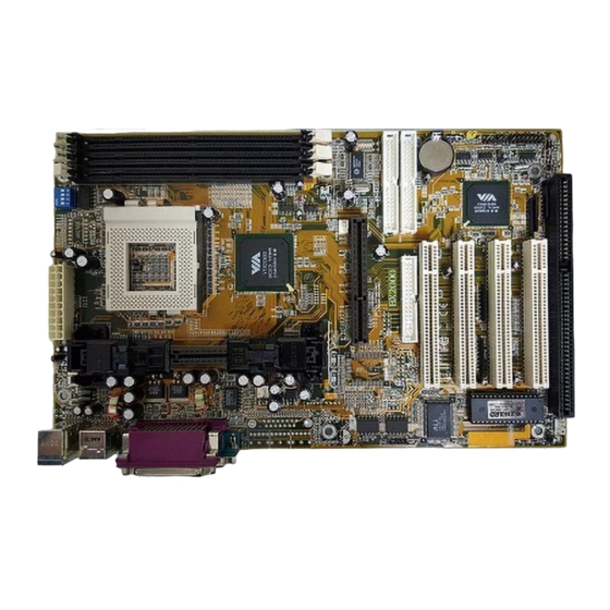
Page 5: Bx2000/Bx2100 Mainboard Diagram
2-2 BX2100/ BX2000 Mainboard Diagram Figure 2-2 Only for BX2100 mainboard... -
Page 6: Quick Reference For Jumpers, Connectors & Expansion Socket
2-3 Quick Reference for Jumpers, Connectors & Expansion Socket Jumpers Jumper Name Description Page JP15 CPU Bus Frequency Selection Refer to page 6 p. 6 CPU Ratio Selector Refer to page 6 p. 6 JP17 CMOS RAM Clear 1-2 Normal ,2-3 Clear CMOS p. -
Page 7: Jumper Settings
Before using your computer, you must follow the steps as follows: 1. Set Jumpers on the Mainboard 2. Install the CPU 3. Install DRAM Modules 4. Install Expansion card Connect Cables, Wires, and Power Supply 2-5 Jumper Settings 1. CPU Bus Frequency Selection : JP15 CPU External Frequency:JP15 JP15... -
Page 8: System Memory (Dram)
WARNING: Make sure your computer is POWER OFF when you CLEAR CMOS. Connect a jumper Cap over this jumper for a few seconds, will clears information stored in the CMOS RAM Chip that input by user, such as hard disk information and passwords. After CLEAR CMOS, you must enter the BIOS setup (by holding down <DEL>... -
Page 9: Expansion Cards
To install a CPU, first turn off your system and remove its cover. Locate the ZIF Socket and open it by first pulling the lever sideways away from the socket then upwards to a 90-degree right angle. Insert the CPU with the white dot as your guide. The white dot should point towards the end of the level. - Page 10 ATX Power Supply connector. This is a new defined 20-pins connector that usually comes with ATX case. The ATX Power Supply allows to use soft power on momentary switch that connect from the front panel switch to 2-pins Power On jumper pole on the mainboard. When the power switch on the back of the ATX power supply turned on, the full power will not come into the system board until the front panel switch is momentarily pressed.
- Page 11 5. Serial Port COMA, COMB: COM1, COM2 COMA is the 9-pin D-Subminiature mail connector. The On-board serial port can be disabled through BIOS SETUP. Please refer to Chapter 3 “INTEGRATED PERIPHERALS SETUP“ section for more detail information. 6. Floppy drive Connector (34-pin block): FDD This connector supports the provided floppy drive ribbon cable.
- Page 12 8. Secondary IDE Connector (40-pin block): IDE2 This connector connects to the next set of Master and Slave hard disks. Follow the same procedure described for the primary IDE connector. You may also configure two hard disks to be both Masters using one ribbon cable on the primary IDE connector and another ribbon cable on the secondary IDE connector.
- Page 13 This 5-pin connector connects to the case-mounted key switch for locking the keyboard for security purposes. See the figure below. 14. Speaker connector: SPEAKER This 4-pins connector connects to the case-mounted speaker. See the figure below. 15. IR infrared module connector: IR1 This connector supports the optional wireless transmitting and receiving infrared module.
- Page 14 ※ Wake On LAN Function worked only when power supply support 5VSB more than 750mA current. Jumpers & Connectors for BX2100 ONLY 19. On Board Audio chip Enabled / Disabled connector: JP4 20. Auxiliary Input connector: JP1 21. CD Audio in connector : JP2,JP3 JP2 and JP3 are the connectors for CD-Audio Input signal, Please connect it to CD-ROM CD-Audio output connector JP2 :CD-Adio/Panasonic...
- Page 15 MIC : Microphone Connector Game/MIDI : for joystick or MIDI Device 23. PC Speaker signal Input connector: SPKIN 1 24. SPDIF (Sony / Philips Digital Interface) Input / Output Connectors: SPDIFIN 1 / SPDIFOUT 25. Optical kit connector: JP18 This connector is for user that has Optical kit(optional) to provide other set of SPDIF INPUT and SPDIF OUTPUT function.
-
Page 16: Award Bios Setup
AWARD BIOS SETUP This mainboard has previously set to its best stable status. If you are not an experienced user, please do not change the default setting. When you are encounter any problem, please choice “LOAD STANDARD DEFAULTS” to restore best setting. Award’s ROM BIOS provides a built-in Setup program which allows user modify the basic system configuration and hardware parameters. -
Page 17: Bios Features Setup
STANDARD CMOS SETUP (Figure 3-1) allows user to configure system setting such as current date and time, type of hard disk drive installed in the system, floppy drive type, and the type of display monitor. Memory size is auto-detected by the BIOS and displayed for your reference. When a field is highlighted (direction keys to move cursor and <Enter>... -
Page 18: Chipset Features Setup
manufacturer’s default values of this mainboard. Again, user can move the cursor by pressing direction keys and <PgDn> of <PgUp> keys to modify the parameters. Pressing [F1] key to display help message of the selected item. This setup program also provide 2 convenient ways to load the default parameter data from BIOS [F6] or CMOS [F7] area if shown data is corrupted. -
Page 19: Power Management Setup
ADVANCED OPTIONS. The parameters in this screen are for system designers, service personnel, and technically competent users only. Do not reset these values unless you understand the consequences of your changes. ROM PCI/ISA BIOS (2A6LGJ1F) CHIPSET FEATURES SETUP AWARD SOFTWARE, INC. Bank 0/1 DRAM Timing : SDRAM 10ns Auto Detect DIMM/PCI Clk : Enabled... - Page 20 ROM PCI/ISA BIOS (2A6LGJ1F) POWER MANAGEMENT SETUP AWARD SOFTWARE, INC. ACPI function : Enabled Primary INTR : ON Power Management : User Define IRQ3 (COM 2) : Primary PM Control by APM : Yes IRQ4 (COM 1) : Primary Video Off After : Suspend IRQ5 (LPT 1) : Primary...
- Page 21 Mode = 1 min., and HDD Power Down = 1 min. User Defined Allows you to set each mode individually. When not disabled, each of the ranges are from 1 min. to 1 hr. except for HDD Power Down which ranges from 1 min. to 15 min. and disable. ...
-
Page 22: Pnp/Pci Configuration Setup
Soft-Off by PWR-BTTN: When Enabled, turning the system off with the on/off button places the system in a very low-power-usage state, with only enough circuitry receiving power to detect power button activity or Resume by Ring activity. The Choice: Instant-Off, Delay 4 Sec. ... -
Page 23: Load Standard Defaults
PNP/PCI CONFIGURATION SETUP AWARD SOFTWARE, INC. PNP OS Installed : No CPU to PCI Write Buffer : Enabled Resources Controlled By : Manual PCI Dynamic Bursting : Enabled Reset Configuration Data: Disabled PCI Master 0 WS Write : Enabled IRQ-3 assigned to : PCI/ISA PnP PCI Delay Transaction : Disabled IRQ-4 assigned to : PCI/ISA PnP PCI#2 Access #1 Retry : Disabled... -
Page 24: Integrated Peripherals Setup
ROM PCI/ISA BIOS (2A6LGJ1F) CMOS SETUP UTILITY AWARD SOFTWARE, INC. STANDARD CMOS SETUP INTEGRATED PERIPHERALS BIOS FEATURES SETUP SUPERVISOR PASSWORD CHIPSET FEATURES SETUP USER PASSWORD POWER MANAGEMENT SETUP Load STANDARD Default (Y/N)? Y PNP/PCI CONFIGUR LOAD OPTIMAL DEFAUL EXIT WITHOUT SAVING LOAD STANDARD DEFAULTS Esc : QUIT ↑↓→←... -
Page 25: Mainboard Driver Install In Win9X,Winnt
Supervisor Password allows you to change all CMOS settings but the User Password setting doesn’t have this function. The way to set up the passwords for both Supervisor and User are as follow: 1. Choose either Supervisor Password or User Password in the Main Menu and press <Enter>. - Page 26 X:\VIA\Driver\SETUP.EXE. After execute Setup .EXE the screen will depend on the OS (Operating System) to show the necessary Driver which you have to install in your system, such like IDE Driver, AGP VXD Driver, VIA chipset Feature Registry and IRQ Routing Miniport Driver . Follow the procedure to install the driver.
- Page 27 two and four channel speakers mode. Support Windows 3.1 / 95 / 98 and Windows NT 4.0. Built-in 32 OHM Earphone buffer and 3D surround. MPU-401 Game/Midi port and legacy audio SB16 support. Downloadable Wave Table Synthesizer, supports Direct Music®. •...
- Page 28 CMI8738/C3DX PCI Audio Joystick Device CMI8738/C3DX PCI Audio Legacy Device DOS mode MPU-401 Emulator 8. Click “start” key 9. Select “Run” 10. Key in the drive and path for Windows application installation program, for example, “X:\CMI8738\ W95-98\APP\SETUP.EXE” 11. Click “OK” to start the installation procedure, and follow the on-screen instructions to finish the installation.
- Page 29 CMI8738\NT40\APP\SETUP.EXE” 14. Click “OK” to start the installation procedure, and follow the on-screen instructions to finish the installation. When all of application softwares have been installed, shut down the Windows NT system, and then reboot your system. Windows Appc. (The Audio Rack) Introduction By means of a user-friendly interface(as easy as operating your home stereo system), this PCI audio rack provides you with the control over your PC’s audio functions, including the advantage...
- Page 30 MIDI Player, Wave Player, and CD Player CD Player (above, similar to Wave Player and MIDI Player) Sel (or Trk) fielX: If you have multiple selections in your playlist, this shows the number of the current selection or CD track. Current File or Track: The name of the current MIDI file, wave audio file, or CD track.
- Page 31 Aux-in: Controls the Aux-in music play or the recording level. PC-SPK: Controls the external PC speaker input level. CX: Controls the CD drive output level, for CD drives configured to play their audio output through the PC’s audio hardware. ...
- Page 32 The Optical Kid includes: Optical Module Optical Cable Software DVD driver An example of optical kit is used to connect the sound card and the MD. The application program setup(please install CMI8738 application program first) When the connection is done, please go to the Start menu and select PCI Audio Applications\Audio Environment Setting...
- Page 33 When all the procedures have been completed, there will be an infrared signal coming from the SPDIF/OUT of the optical fiber of the sound card.
- Page 34 Please note that signal beam may cause severe damage to the eyes. For your safety, please point the output end to a piece of white paper to check if thebeam is in function. Please connect the output signal to the MD input, then play the music via the MP3 player:...
- Page 35 Please note that in playback, if there is no gap longer than three seconds between each track, the MD can not recognize the tracks and will record all of them into one. It is recommended that you set the gap time to 3~5 seconds to meet all type of MD requirements.
- Page 36 About Recording 24bit Audio Setting 24-bit audio can only be applied to SPDIF IN/OUT mode; it does not apply to other modes such as the four channels or the analog. No sound will be heard while in playback, yet it can be recorded.
- Page 37 The un-selected area will be gray out.
- Page 38 The un-selected area will be gray out.
- Page 39 The un-selected area will be gray out. You can double-click this circuit icon to have the following setting box. By means of this setting box, you can also complete the above-mentioned setting procedures.
- Page 40 BX2100 SPDIF/IN An example of Portable CD Player(Output) to BX2100(Optical Input)Setup...
- Page 41 When the connection is done, please go to the Start menu and select PCI Audio Applications\Audio Environment Setting...
- Page 42 3.Loopback(bypass)mode setup CD ROM(Digital Output) to BX2100(SPDIF/IN)Setup When the connection is done, please go to the Start menu and select PCI Audio Applications\Audio Environment Setting...
- Page 43 Please follow these setting procedures.
- Page 44 Now you can insert the CD into the CD ROM drive, then activate C-MEDIA CD player and push the ”play” button to do the recording job. Please note that you have to set the MD in the simultaneous-recording mode.
-
Page 45: Quick Troubleshooting Guide
Chapter 5 Quick Troubleshooting Guide If the result of your diagnostic is “call service”, please have the following information ready before you contact for any technical support. 1. The CPU (Central Processing Unit) you are using along with its require setting. 2. -
Page 46: Frequently Asked Questions And Answers
CPU; therefore system can read the temperature and display it in the BIOS. Q: Why the mainboard can’t installed both Pentium II/III CPU and Socket 370 CPU together? A:BX2000/BX2100 Mainboard is design for single CPU. It can’t accept dual CPU at the same time.