Table of Contents
Advertisement
Quick Links
TECHNICAL MANUAL
Of
Intel QM77 Express Chipset
Based Mini-ITX M/B
NO. G03-NF9G-F
Revision: 3.0
Release date: October 1, 2019
Trademark:
* Specifications and Information contained in this documentation are furnished for information use only, and are
subject to change at any time without notice, and should not be construed as a commitment by manufacturer.
Advertisement
Table of Contents

Related Manuals for JETWAY NF9G-QM77


Summary of Contents for JETWAY NF9G-QM77
- Page 1 TECHNICAL MANUAL Intel QM77 Express Chipset Based Mini-ITX M/B NO. G03-NF9G-F Revision: 3.0 Release date: October 1, 2019 Trademark: * Specifications and Information contained in this documentation are furnished for information use only, and are subject to change at any time without notice, and should not be construed as a commitment by manufacturer.
- Page 2 Environmental Protection Announcement Do not dispose this electronic device into the trash while discarding. To minimize pollution and ensure environment protection of mother earth, please recycle.
-
Page 3: Table Of Contents
TABLE OF CONTENT ENVIRONMENTAL SAFETY INSTRUCTION ................iii USER’S NOTICE ........................iv MANUAL REVISION INFORMATION ..................iv ITEM CHECKLIST ........................iv CHAPTER 1 INTRODUCTION OF THE MOTHERBOARD FEATURE OF MOTHERBOARD ................1 SPECIFICATION ......................2 LAYOUT DIAGRAM ....................3 CHAPTER 2 HARDWARE INSTALLATION JUMPER SETTING .....................8 CONNECTORS AND HEADERS ................12 2-2-1 CONNECTORS .....................12 2-2-2... -
Page 4: Environmental Safety Instruction
Environmental Safety Instruction Avoid the dusty, humidity and temperature extremes. Do not place the product in any area where it may become wet. 0 to 60 centigrade is the suitable temperature. (The figure comes from the request of the main chipset) ... -
Page 5: User's Notice
USER’S NOTICE COPYRIGHT OF THIS MANUAL BELONGS TO THE MANUFACTURER. NO PART OF THIS MANUAL, INCLUDING THE PRODUCTS AND SOFTWARE DESCRIBED IN IT MAY BE REPRODUCED, TRANSMITTED OR TRANSLATED INTO ANY LANGUAGE IN ANY FORM OR BY ANY MEANS WITHOUT WRITTEN PERMISSION OF THE MANUFACTURER. -
Page 6: Chapter 1 Introduction Of The Motherboard Feature Of Motherboard
Chapter 1 Introduction of the Motherboard Feature of Motherboard Intel ® QM77 express chipset Intel ® Socket G (rPGA988B) supporting compatible Intel Core™ i3, i5, i7 Mobile Processors under 45W power consumption, with low power consumption never denies high performance ... -
Page 7: Specification
1-2 Specification Spec Description Design Mini-ITX form factor 6 layers ; PCB size: 17.0x17.0cm Intel QM77 Express Chipset Chipset Intel socket G (rPGA 988B) Support up to Intel Core™ i3, i5, i7 Mobile Processors under CPU Socket 45W power consumption * for detailed CPU support information please visit our website ... -
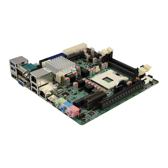
Page 8: Layout Diagram
KBMS header x1 LVDS header x1 LVDS Inverter header x1 HDMI_SPDIF header x1 GPIO header x1 Serial port header x3 TX-RXCOM header x1 USB 2.0 header x2 (support four expansion USB 2.0 ports) ... - Page 9 CPUFAN Header RJ-45 Port Display Port Intel rPGA988 DDRIII SODIMM Slot x 2 CPU Socket Mini-PCIE Slot (DDRIII 1066/1333) Line-OUT Line-IN MIC-IN Front Panel Audio Header KBMS Header HDMI_SPDIF Header PCI Express x16 Slot (PE1) Headers for Jetway Daughter Board Expansion...
- Page 10 Motherboard Jumper Position JP10 JP12 LAN Chip LAN Chip JP11 JBAT Audio Chip CASE_OPEN...
- Page 11 Jumper Jumper Name Description JBAT CMOS RAM Clear Function Setting 3-pin Block LVDS PVCC 5V/3.3V Select 3-pin Block Inverter 5V/12V Select 3-pin Block mSATA/Mini PCI-E Power VCC 3.3V /3VSB 3-pin Block Select JP11 Mini PCI-E Power VCC 3.3V /3VSB Select 3-pin Block JP10 COM4 Pin9 Function Select...
- Page 12 Power LED 3-pin Block SPEAK Speaker Header 4-pin Block JW_FP Front Panel Header(PWR LED/ HD 9-pin block LED/ /Power Button /Reset) CPU FAN CPU FAN Header 4-pin Block SYSFAN1/SYSFAN2 SYSFAN1/2 Header 3-pin Block CN1/CN2 Jetway Daughter Board Header x2 35-pin Block...
-
Page 13: Chapter 2 Hardware Installation
Chapter 2 Hardware Installation 2-1 Jumper Setting (1) JBAT (3-pin): Clear CMOS JBAT 1-2 Short: Normal; 2-3 Short: Clear CMOS CMOS Clear Setting (2) JP3 (3-pin): LVDS PVCC 5V / 3.3V Function Select 1-2 closed: LVDS PVCC= 5V 2-3 closed : LVDS PVCC= 3.3V... - Page 14 (3) JP5 (3-pin): Inverter 5V/12V Select 1-2 closed: Inverter 5V selected; 2-3 closed: Inverter 12V select (4) JP9 (3-pin): Mini-SATA/Mini-PCIE Power VCC3.3V/ 3VSB Function Select 1-2 closed: Mini-SATA/Mini-PCIE Slot VCC= VCC3.3V; 2-3 closed: Mini-SATA/Mini-PCIE Slot VCC=3VSB...
- Page 15 (5) JP11: Mini PCI-E Power VCC3.3V/ 3VSB Function Select JP11 1-2 closed: Mini PCI-E Slot VCC= VCC3.3V; JP11 2-3 closed: Mini PCI-E Slot VCC=3VSB (6) JP10 (6-pin): COM4 Pin9 Function Select JP10 1-2 closed: RS232; 3-4 closed : +12V; 5-6 closed : +5V...
- Page 16 (7) JP12 (6-pin): COM4 Header RS232/422/485 Function Select JP12 1-2 closed: RS232; 3-4 closed : RS485; 5-6 closed : RS422 (8)CASE_OPEN(2-pin): Case Open Message Display Function Select Pin 1-2 shorted: Case open display function enabled. Use needs to enter BIOS and enable ‘Case Open Detect’...
-
Page 17: Connectors And Headers
Connectors and Headers 2-2-1 Connectors (1) Rear Panel Connectors RJ-45 LAN Ports Serial Port Line-OUT USB 3.0 Ports Line-IN Display Port MIC-IN USB 2.0 Ports HDMI Port VGA Port (2) ATXPWR (24-pin block): Main Power Connector PIN ROW1 ROW2 +3.3V +3.3V +3.3V -12V... - Page 18 (3) ATX12V (4-pin block): ATX12V Type Power Connector Pin1 Pin No. Definition +12V +12V (4) SATA1/SATA2: SATAIII Port connector These connectors are high-speed SATAIII ports that support 6 GB/s transfer rate. Pin No. Defnition *Note: In the case that user install Mini SATA hard disk to MSATA slot, SATA2 port will be functionless.
- Page 19 (5) SATA3/SATA4/SATA5/SATA6:SATAII Port connector These connectors are high-speed SATAII ports that support 3 GB/s transfer rate. Pin No. Defnition (6) MSATA: Mini -SATAIII Port Connector MSATA slot can function as Mini-SATA connecter or full-size Mini-PCIE slot. When function as Mini-SATA connector it can be connected to a single solid-state hard disk driver and supports SATA 6Gb/s specification.
-
Page 20: Headers
2-2-2 Headers (1) FP_AUDIO (9-pin): Line-Out, MIC-In Header This header connects to Front Panel Line-out, MIC-In connector with cable. FP_AUDIO Pin 1 Line-Out, MIC Header (2) KBMS (6-pin): PS/2 Keyboard & Mouse Header Pin1... - Page 21 (3) HDMI_SPDIF (2-pin): HDMI-SPDIF Out header Pin1 HDMI_SPDIF Header (4) COM2/3/4 (9-Pin): Serial Port Header Pin6 Pin1 Pin5...
- Page 22 (5) TX-RXCOM (4-pin): RS422/485 Header Pin 1 (6) GPIO (10-pin): GPIO Header Pin 1...
- Page 23 (7) USB1/USB2 (9-pin): USB 2.0 Port Header Pin 1 (8) USB4 (19-pin): USB 3.0 Port Header Pin 1...
- Page 24 (9)SM_BUS (4-pin): SM BUS Header Pin 1 (10) LVDS (35-Pin): LVDS Header Pin 2 Pin 1...
- Page 25 Pin NO. Pin Define Pin NO. Pin Define Pin 1 LVDSB_DATAN3 Pin 2 LVDSB_DATAP3 Pin 3 LVDSB_CLKBN Pin 4 LVDSB_DATABP Pin 5 LVDSB_DATAN2 Pin 6 LVDSB_DATAP2 Pin 7 LVDSB_DATAN1 Pin 8 LVDSB_DATAP1 Pin 9 LVDSB_DATAN0 Pin 10 LVDSB_DATAP0 Pin 11 LVDS_DDC_DATA Pin 12 LVDS_DDC_CLK...
- Page 26 (12) CIR (7-Pin): CIR Header Pin 1 (13) NIC_LED1/NIC_LED2 (2-pin): LANLED Header Pin1 (14) PWR LED(3-pin): PWR LED Header The Power LED is light on while the system power is on. Connect the Power LED from the system case to this pin header.
- Page 27 (15) SPEAK (4-pin): Speaker Header This 2-pin header connects to the case-mounted speaker. See the figure below. SPEAK Pin 1 PWRLED Pin 1 (16) JW-FP (9-pin): Front Panel Header Pin 1...
- Page 28 (17) CPUFAN (4-pin)/SYSFAN1 (3-pin)/SYSFAN2 (3-pin): FAN Speed Headers Pin1 +12V Fan Power Fan Clock Pin1 SYSFAN1/SYSFAN2 Header CPUFAN (18) CN1/CN2 (35-Pin): Jetway Daughter Board Header These two Headers can add the COM Port card/ LAN card. Pin 1 Pin 1 CN1/CN2 Header...
-
Page 29: Chapter 3 Introducing Bios
Chapter 3 Introducing BIOS Notice! The BIOS options in this manual are for reference only. Different configurations may lead to difference in BIOS screen and BIOS screens in manuals are usually the first BIOS version when the board is released and may be different from your purchased motherboard. Users are welcome to download the latest BIOS version form our official website. -
Page 30: Bios Menu Screen
BIOS Menu Screen The following diagram show a general BIOS menu screen: Menu Bar General Help Items Current Setting Value Menu Items Function Keys BIOS Menu Screen Function Keys In the above BIOS Setup main menu of, you can see several options. We will explain these options step by step in the following pages of this chapter, but let us first see a short description of the function keys you may use here: ... -
Page 31: Getting Help
Press (up, down) to choose, in the main menu, the option you want to confirm or to modify. Press <Enter> to select. Press <+>/<–> keys when you want to modify the BIOS parameters for the active option. -
Page 32: Main Menu
User can press the right or left arrow key on the keyboard to switch from menu bar. The selected one is highlighted. Main Menu Main menu screen includes some basic system information. Highlight the item and then use the <+> or <-> and numerical keyboard keys to select the value you want in each item. -
Page 33: Advanced Menu
3-7 Advanced Menu Launch PXE OpROM Policy The optional settings are: [Do not launch]; [UEFI only]; [Legacy only]. Use this item to enable or disable boot option for legacy network devices. ERP Function Use this item to enable or disable ERP function for this board. This item should be set as [Disabled] if you wish to have Active All Wakeup Function. - Page 34 Extended Tag If set as [Enabled] it will allow device to use 8-bit tag field as a requester. No Snoop Use this item to enable or disable PCI Express device No Snoop option. Maximum Payload Use this item to set maximum payload of PCI Express device or allow system BIOS to select the value.
- Page 35 S3 Video Repost Use this item to enable or disable S3 video report. Wakeup Function Settings ► Press [Enter] to make settings for the following sub-items: Wake System with Fixed Time Use this item to enable or disable system wake on alarm event. When set as [Enabled], system will wake on the hour/min/sec specified.
- Page 36 Adjacent Cache Line Prefetch Use this item to turn on/off prefetching of adjacent cache lines. SATA Configuration ► Press [Enter] to make settings for the following sub-items: SATA Controller(s) The optional settings are: [Disabled]; [Enhanced]. IDE Legacy/Native Mode Select The optional settings are: [Native]; [Legacy]. SATA Mode Selection The optional settings are: [IDE];...
- Page 37 The optional settings are: [Disabled]; [Enabled]. Un-Configure ME The optional settings are: [Disabled]; [Enabled]. Amt Wait Timer Use this item to set time to wait before sending ASF_GET_BOOT_OPTIONS. Disable ME The optional settings are: [Disabled]; [Enabled]. Use this item to enable or disable alert specification format. Active Remote Assistance Process The optional settings are: [Disabled];...
- Page 38 itself to the host controller. ‘Auto’ uses default value: for a root port it is 100 ms, for a hub port the delay is taken from hub descriptor. The optional settings: [Auto]; [Manual].Select [Manual] you can set value for the following sub-item: Device Power-up delay in seconds, the delay range in from 1 to 40 seconds, in one second increments.
- Page 39 Serial Port Configuration ► Press [Enter] to make settings for the following sub-items: Super IO Configuration ► COM1 Port Configuration/ COM2 Port Configuration/COM3 Port Configuration Press [Enter] to make settings for the following items: Serial Port Use this item to enable or disable serial port. Change Settings Use this item to select an optimal setting for super IO device.
-
Page 40: Chipset Menu
Press [Enter] to make settings for CPU PPM Configuration: CPU PPM Configuration: EIST Use this item to enable or disable Intel SpeedStep. Turbo Mode Use this item to enable or disable Turbo mode. CPU C3 Report Use this item to enable or disable CPU C3 (ACPI C2) report to OS. CPU C6 Report Use this item to enable or disable CPU C6 (ACPI C3) report to OS. - Page 41 PCH-IO Configuration ► Press [Enter] to make settings for the following sub-items: ► USB Devices Configuration Press [Enter] to make further settings USB device configuration. USB Device Configuration: XHCI Pre-Boot Driver Use this item to enable or disable XHCI Pre-Boot Driver Support. XHCI Mode The optional settings are: [Smart Auto];...
- Page 42 Onboard Lan1 Controller Use this item to enable or disable onboard LAN controller. Wake on LAN1 from S5 Use this item to enable or disable integrated LAN to wake the system. Onboard Lan2 Device Use this item to control the PCI Express root port. High Precision Event Timer Configuration High Precision Timer The optional settings are: [Enabled];...
- Page 43 by the internal graphics device. DVMT Total Gfx Mem Use this item to select DVMT 5.0 total graphics memory size used by the internal graphics device. LCD Control Primary IGFX Boot Display The optional settings are: [VBIOS default]; [CRT]; [HDMI]; [DP]; [LVDS]. Secondary IGFX Boot Display The optional settings are: [Disabled];...
-
Page 44: Boot Menu
Use this item to set maximum memory frequency selection in Mhz. MMode Support The optional settings are: [Auto]; [1N Mode]; [2N Mode]. Memory Remap Use this item to enable or disable memory remap above 4G. The optional settings are: [Enabled]; [Disabled]. 3-9 Boot Menu... - Page 45 Boot Configuration: Setup Prompt Timeout Use this item to set number of seconds to wait for setup activation key. Bootup Numlock State Use this item to select keyboard numlock state. The optional settings are: [On]; [Off]. Quiet Boot The optional settings are: [Enabled]; [Disabled]. Fast Boot The optional settings are: [Enabled];...
-
Page 46: Security Menu
3-10 Security Menu Security menu allow users to change administrator password and user password settings. -
Page 47: Save & Exit Menu
3-11 Save & Exit Menu Save Changes and Reset This item allows user to reset the system after saving the changes. Discard Changes and Reset This item allows user to reset the system without saving any changes. Restore Defaults Use this item to restore /load default values for all the setup options. Save as User Defaults Use this item to save the changes done so far as user defaults. -
Page 48: Appendix
Launch EFI Shell from file system device This item is for attempts to launch EFI shell application (Shell x64.efi) from one of the available filesystem devices. Appendix How to set CN1, CN2 add-on card to run PCIE X1 or PCIE X4 mode: User can purchase compatible add-on card to install on CN1 &... - Page 49 5. Next time when you use another add-on card that supports PCIE X1 mode only, need page download file ‘NF9G’ ‘NF9G_PCIEX1SET.rar’, uncompress the file and execute ‘X1.BAT’ to change BIOS settings for the card to run in PCIE X1 mode. 6.