Table of Contents
Advertisement
Quick Links
740DMP/740DMU/740DMZ
USER'S MANUAL
M/B For Socket-A Athlon/Duron Processor
NO. G03-740DMR1A
Release date: September 2002
Trademark:
* Specifications and Information contained in this documentation are furnished for information use only, and are
subject to change at any time without notice, and should not be construed as a commitment by manufacturer.
Advertisement
Table of Contents

Related Manuals for JETWAY 740DMR1A


Summary of Contents for JETWAY 740DMR1A
- Page 1 740DMP/740DMU/740DMZ USER'S MANUAL M/B For Socket-A Athlon/Duron Processor NO. G03-740DMR1A Release date: September 2002 Trademark: * Specifications and Information contained in this documentation are furnished for information use only, and are subject to change at any time without notice, and should not be construed as a commitment by manufacturer.
-
Page 2: Table Of Contents
TABLE OF CONTENT USER’S NOTICE ......................ii MANUAL REVISION INFORMATION ................ii COOLING SOLUTIONS ....................ii CHAPTER 1 INTRODUCTION OF 740DMP/740DMU/740DMZ MOTHERBOARD 1-1 FEATURE OF MOTHERBOARD................1 1-2 SPECIFICATION .....................2 1-3 PERFORMANCE LIST ...................3 1-4 LAYOUT DIAGRAM & JUMPER SETTING ............4 CHAPTER 2 HARDWARE INSTALLATION 2-1 HARDWARE INSTALLATION STEPS ..............6 2-2 CHECKING MOTHERBOARD'S JUMPER SETTING........6 2-3 INSTALL CPU ......................8... -
Page 3: User's Notice
USER’S NOTICE COPYRIGHT OF THIS MANUAL BELONGS TO THE MANUFACTURER. NO PART OF THIS MANUAL, INCLUDING THE PRODUCTS AND SOFTWARE DESCRIBED IN IT MAY BE REPRODUCED, TRANSMITTED OR TRANSLATED INTO ANY LANGUAGE IN ANY FORM OR BY ANY MEANS WITHOUT WRITTEN PERMISSION OF THE MANUFACTURER. THIS MANUAL CONTAINS ALL INFORMATION REQUIRED TO USE740DMP/740DMU/740DMZ MOTHER-BOARD AND WE DO ASSURE THIS MANUAL MEETS USER’S REQUIREMENT BUT WILL CHANGE, CORRECT ANY TIME WITHOUT NOTICE. -
Page 4: Chapter 1 Introduction Of 740Dmp/740Dmu/740Dmz Motherboard
Chapter 1 Introduction of 740DMP/740DMU/740DMZ Motherboard 1-1 Feature of motherboard The 740DMP/740DMU/740DMZ motherboard is design for use AMD Athlon/ Duron/Athlon XP 200MHz/266MHz (Double Data Rate) Front Side Bus Frequency CPU, which utilize the Socket-A design and the memory size expandable to 2.0GB. The motherboard use the newest SiS740/962L chipset for 740DMP/740DMU and SiS740/962 for 740DMZ, whose 133MHz/266MHz (Double Data Rate) Front Side Bus frequency and 266MHz memory interface delivers a clear upgrade path to the... -
Page 5: Performance List
∗ Micro ATX form factor 4 layers PCB size: 24.5x22.0cm Design ∗ SiS 740 North Bridge Chipset Chipset ∗ SiS 962L MuTIOL Media I/O Chipset (for 740DMP/740DMU) ∗ SiS 962 MuTIOL Media I/O Chipset (for 740DMZ) ∗ Support AMD Athlon 700MHz∼1.4GHz processor CPU Socket ∗... -
Page 6: Layout Diagram & Jumper Setting
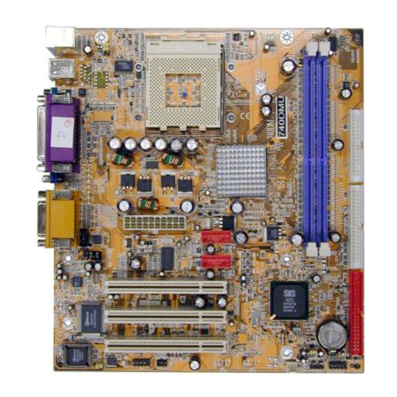
The following performance data list is the testing result of some popular benchmark testing programs. These data are just referred by users, and there is no responsibility for different testing data values gotten by users (the different Hardware & Software configuration will result in different benchmark testing results.) Performance Test Report AMD Athlon XP 2600+... - Page 7 (for 740DMP/740DMZ) PRINT GAME/MIDI PORT PS/2 Mouse PS/2 Keyboard COM1 LINE-IN LINE-OUT USB Power ON Jumper (JP2) CPU Socket K/B Power ON Jumper (JP1) PS2 KB/Mouse Port CPU FAN USB Port/ LAN Connector (for 740DMP/740DMZ) DDR Socket X2 PC99 Back Panel Floppy Connector SIS 740 Chip ATX Power Conn.
- Page 8 CMOS RAM Clear 3-pin Block Keyboard Power On Enable/Disabled 3-pin Block USB Device Power On Enabled/Disabled 3-pin Block Keyboard Password Clear 3-pin Block Connectors Connector Name Description Page ATX _ PW ATX Power Connector 20-pin Block P.12 KBMS1 PS/2 Mouse & PS/2 Keyboard 6-pin Female P.12 Connector...
-
Page 9: Hardware Installation Steps
2-1 Hardware installation Steps Before using your computer, you had better complete the following steps: 1. Check motherboard setting 2. Install CPU 3. Install Memory 4. Install Expansion cards 5. Connect Ribbon cables, Panel wires, and power supply 6. Setup BIOS 7. -
Page 10: Glossary
3. After over clocking system boot fail 1-2 closed Clear CMOS 2-3 closed Normal (Default) CMOS RAM Clear Setting 3. Keyboard/USB Device Power On function Enabled/Disabled: JP1/JP2 When setting Enabled you can using keyboard by key in password to power on system, or by USB Device to power on system. -
Page 11: About Amd Athlon & Duron 462-Pin Cpu
Chipset (or core logic) - two or more integrated circuits which control the interfaces between the system processor, RAM, I/O devises, and adapter cards. Processor slot/socket - the slot or socket used to mount the system processor on the motherboard. Slot (AGP, PCI, ISA, RAM) - the slots used to mount adapter cards and system RAM. -
Page 12: Install Memory
processor and motherboard overheat and damage, you may install an auxiliary cooling FAN, if necessary. WARNING! Due to this motherboard provides new function of protecting CPU ; you must connect the CPU FAN connector on FAN1 location in order to obtain this feature. -
Page 13: Expansion Card
NOTE! When you install DIMM module fully into the DIMM socket the eject tab should be locked into the DIMM module very firmly and fit into its indention on both sides. WARNING! For the DDR SDRAM CLOCK is set at 133MHz, use only DDR266- compliant DDR Modules. -
Page 14: Interrupt Request Table For This Motherboard
Programmable Interrupt Communications Port (COM2) Communications Port (COM1) Sound Card (sometimes LPT2) Floppy Disk Controller Printer Port (LPT1) System CMOS/Real Time Clock ACPI Mode when enabled 10 * IRQ Holder for PCI Steering 11 * IRQ Holder for PCI Steering 12 * PS/2 Compatible Mouse Port Numeric Data Processor... - Page 15 ATX Power Supply connector. This is a new defined 20-pins connector that usually comes with ATX case. The ATX Power Supply allows to use soft power on momentary switch that connect from the front panel switch to 2-pins Power On jumper pole on the motherboard.
- Page 16 PS/2 PRINT GAME/MIDI PORT Mouse PS/2 COM1 LINE-IN Keyboard LINE-OUT Floppy drive Connector (34-pin block): FDD This connector supports the provided floppy drive ribbon cable. After connecting the single plug end to motherboard, connect the two plugs at other end to the floppy drives. Pin 1 Floppy Drive Connector (10) Primary IDE Connector (40-pin block): IDE1...
-
Page 17: Headers
IDE2 Pin 1 Secondary IDE Connector • Two hard disks can be connected to each connector. The first HDD is referred to as the “Master” and the second HDD is referred to as the “Slave”. • For performance issues, we strongly suggest you don’t install a CD-ROM or DVD-ROM drive on the same IDE channel as a hard disk. - Page 18 Serial Port2 COM2 Header (9-pin) : COM2 COM2 Note: Orient the read marking on the COM2 ribbon cable to pin 1 Pin 1 Serial Port2 COM2 Header 1394 Connector Header (9-pin): 1394A, 1394B (for 740DMZ) 1394A 1394B Pin 1 Pin 1 1394 Connector Headers IDE Activity LED: IDE LED This connector connects to the hard disk activity indicator light on the case.
- Page 19 JW _ FP1 SPEAK Pin 1 Pin 1 System Case Connections (10) Wake On-LAN Headers (3-pin) : WOL This connector connects to a LAN card with a WAKE ON-LAN output. This connector power up the system when a wake up signal is received through the LAN card. NOTE: This feature requires that Wake On LAN or Ring In Wake up is enabled.
- Page 20 (12) IR infrared module Headers (5-pin) : IR This connector supports the optional wireless transmitting and receiving infrared module. You must configure the setting through the BIOS setup to use the IR function. Pin 1 IR infrared module Headers (13) CD Audio-In Headers (4-pin) : CD _ IN CDIN is the connector for CD-Audio Input signal.
-
Page 21: Starting Up Your Computer
2-7 Starting Up Your Computer 1. After all connection are made, close your computer case cover. 2. Be sure all the switch are off, and check that the power supply input voltage is set to proper position, usually in-put voltage is 220V∼240V or 110V∼120V depending on your country’s voltage used. -
Page 22: Chapter 3 Introducing Bios
Chapter 3 Introducing BIOS The BIOS is a program located on a Flash Memory on the motherboard. This program is a bridge between motherboard and operating system. When you start the computer, the BIOS program gain control. The BIOS first operates an auto-diagnostic test called POST (power on self test) for all the necessary hardware, it detects the entire hardware device and configures the parameters of the hardware synchronization. -
Page 23: The Main Menu
3-3 The Main Menu Once you enter Award BIOS CMOS Setup Utility, the Main Menu (Figure 3-1) will appear on the screen. The Main Menu allows you to select from fourteen setup functions and two exit choices. Use arrow keys to select among the items and press <Enter> to accept or enter the sub-menu. -
Page 24: Standard Cmos Features
Load Optimized Defaults Use this menu to load the BIOS default values that are factory settings for optimal performances system operations. Load Standard Defaults Use this menu to load the BIOS default values for the minimal/stable performance system operation. Set Supervisor/User Password Use this menu to set User and Supervisor Passwords. -
Page 25: Advanced Bios Features
Time The time format is <hour><minute><second>. Primary Master/Primary Slave Secondary Master/Secondary Slave Press PgUp/<+> or PgDn/<–> to select Manual, None, Auto type. Note that the specifications of your drive must match with the drive table. The hard disk will not work properly if you enter improper information for this category. - Page 26 Anti-Virus Protection Allows you to choose the VIRUS Warning feature for IDE Hard Disk boot sector protection. If this function is enabled and someone attempt to write data into this area, BIOS will show a warning message on screen and alarm beep. Disabled (default) No warning message to appear when anything attempts to access the boot sector or hard disk partition table.
-
Page 27: Advanced Chipset Features
Fast (default) The A20 signal is controlled by port 92 or chipset specific method. Typematic Rate Setting Keystrokes repeat at a rate determined by the keyboard controller. When enabled, the typematic rate and typematic delay can be selected. The settings are: Enabled/Disabled. Typematic Rate (Chars/Sec) Sets the number of times a second to repeat a keystroke when you hold the key down. -
Page 28: Dram Timing Settings
Selecting Enabled allows caching of the system BIOS ROM at F0000h-FFFFFh, resulting in better system performance. However, if any program writes to this memory area, a system error may result. The settings are: Enabled and Disabled. Video RAM Cacheable Select Enabled allows caching of the video BIOS, resulting in better system performance. However, if any program writes to this memory area, a system error may result. -
Page 29: Integrated Peripherals
SDRAM CAS Latency When synchronous DRAM is installed, the number of clock cycles of CAS latency depends on the DRAM timing. The settings are: 2T and 2.5T. 3-7 Integrated Peripherals CMOS Setup Utility – Copyright(C) 1984-2002 Award Software Integrated Peripherals >... -
Page 30: Onchip Device Function
Primary Slave Auto Menu Level >> Secondary Master PIO Auto Secondary Slave Auto Primary Master Ultra DMA Auto Primary Slave Ultra DMA Auto Secondary Master Ultra DMA Auto Secondary Slave Ultra DMA Auto IDE DMA Transfer Access Enabled IDE Burst Mode Enabled IDE HDD Block Mode Enabled... -
Page 31: Onboard Super Io Function
Midi Port Address Disabled Menu Level >> Midi Port IRQ AC97 Modem Device Auto →(for 740DMZ) 1394 Controller Disabled USB Host Controller Enabled USB Keyboard Legacy Support Disabled ETHERNET Function Enabled →(for 740DMP/740DMZ) ETHERNET Address ID Input Press Enter Current ETHERNET Address is 003018-xxxxxx ↑... -
Page 32: Power Management Setup
↑ ↓ → ← Move Enter:Select +/-/PU/PD:Value F10:Save ESC:Exit F1:General Help F5:Previous Values F6:Optimized Defaults F7:Standard Defaults Onboard FDD Controller Select Enabled if your system has a floppy disk controller (FDD) installed on the system board and you wish to use it. If you install add-on FDC or the system has no floppy drive, select Disabled in this field. -
Page 33: Pm Wake Up Events
ACPI Function Enabled Item Help Video Off Option Always Off Video off Method V/H SYNC+Blank MODEM Use IRQ Menu Level > Hot Key Function as Power Off Power Button Function Instant Off > PM Wake Up Events Press Enter ↑ ↓ → ← Move Enter:Select +/-/PU/PD:Value F10:Save ESC:Exit F1:General Help F5:Previous Values F6:Optimized Defaults... -
Page 34: Pnp/Pci Configuration Setup
Ring Power Up Control Disabled Menu Level >> MACPME Power Up Control Disabled PCIPME Power Up Control Disabled KB Power On Password Enter Power Up by Alarm Disabled x Month Alarm x Day of Month Alarm x Time (hh:mm:ss) Alarm 0 : 0 : 0 ↑... -
Page 35: Irq Resources
Reset Configuration Data Normally, you leave this field Disabled. Select Enabled to reset Extended System Configuration Data (ESCD) when you exit Setup if you have installed a new add-on and the system reconfiguration has caused such a serious conflict that the operating system can not boot. The settings are: Enabled and Disabled. -
Page 36: Miscellaneous Control
Detect CPUFAN in Post Enabled Menu Level > 25 ° C Current System Temperature 38 ° C Current CPU Temperature Current CPUFAN Speed 5000 rpm Current SYSFAN Speed 5000 rpm Vcore 1.78V Vcc3.3 3.31V + 5V 4.98V +12V 12.22V -12V -12.36V VBAT(V) 3.21V... -
Page 37: Load Standard/Optimized Defaults
The settings are: Enabled, Disabled. Host Clock at next Boot is This item allows you to select CPU frequency step by step increasing The choice are: 100MHz∼132MHz, 133MHz∼200MHz. DRAM Clock at next Boot is This field displays the capability of the memory modules that you can use The choice is either 100MHz or 133MHz or 166MHz. -
Page 38: Chapter 4 Driver & Free Program Installation
password every time your system is rebooted. This would prevent unauthorized use of your computer. You determine when the password is required within the BIOS Features Setup Menu and its Security option. If the Security option is set to “System”, the password will be required both at boot and at entry to Setup. -
Page 39: Ide Install Sis Mini Ide Driver
From MAGIC INSTALL MENU you may make 12 selections: 1. IDE install SiS MINI IDE driver 2. VGA install SiS 650/740 On-chip VGA driver 3. SOUND install ALC PCI Audio driver 4. LAN install LAN controller driver (for 740DMP/740DMZ) 5. USB2.0 install USB 2.0 driver 6. -
Page 40: Vga
Select components and Click Next Click FINISH and Restart Computer 4-2 VGA Install SiS 650/740 VGA Driver The path of the file: for WINDOWS 9X is X:\SIS650\VGA\WIN9X\SETUP.EXE (including Windows 98/98SE/ME) for WINDOWS NT4.0 is X:\SIS650\VGA\WINNT40 for WINDOWS 2000 is X:\SIS650\VGA\WIN2000\SETUP.EXE For WINDOWS 98/98SE/ME/2000/XP Click VGA when Magic Install MENU Click Next when SiS Compatible... -
Page 41: Sound Install Alc Audio Codec Driver
After Setup complete please select restart my computer now and click Finish to complete setup 4-3 Sound Install ALC Audio Codec Driver 1. Click SOUND when MAGIC INSTALL 2. Then auto detect operation system language MENU appears edition, click OK, start to install DRIVER 3. -
Page 42: Lan
5. Sound Effect select and KaraOK Mode 6. Manual Sound Effect Setting Function Note: The path of the file For WIN98/NT4.0/WIN2K is X:\CODEC\ALCCODEC\SETUP.EXE 4-4 LAN install LAN controller driver (for 740DMP/740DMZ) The path of the file: for WINDOWS 9X/2000/XP is X:\SIS650\LANDRV\SETUP.EXE for WINDOWS NT4.0 is X:\SIS650\LANDRV\NT40 WINDOWS 95/98/98SE/98ME/2000/XP Setup 1. -
Page 43: Pc-Health Winbond Hardware Doctor Monitoring Software
Driver setup completely Click NEXT when SiS PCI LAN Driver Setup appears 4-5 PC-HEALTH Winbond Hardware Doctor Monitoring Software 1. Click PC-Health when Magic Install Menu 2. When Winbond Hardware Doctor Setup appears Window appears Click NEXT, Select destination directory Click NEXT, Enter program folders name and Click NEXT, When Start copying files windows appears Click NEXT... -
Page 44: Magic Bios Install Bios Live Update Utility
system voltage SYSTEM FAN speed and CPU/ SYSTEM Temperature. If the value is over default setting the system will have warring picture and beeps 4-6 MAGIC BIOS Install BIOS Live Update Utility Click Magic BIOS when Magic Install Click Next to install the Magic BIOS in MENU appears Destination Folder After finish Setup you will have a Magic... -
Page 45: Pc-Cillin
will auto-check your BIOS version upgrade BIOS, the system will clear CMOS and automatically restart Click Yes if you want to update the BIOS When System programming BIOS don’t turn otherwise choose No to exit off power, after finish update BIOS, the system will clear CMOS and automatically Restart When choose From Local Driver to update... - Page 46 MENU appear CILLIN 2002 main menu appears, and Click NEXT when "Install Shield Wizard For PC- CILLIN 2002" (2) Click Open Manual. you can learn PC- CILLIN 2002 how to use 3. This is license agreement, select "I Accept 4. Click NEXT and Enter your Customer the terms"...
-
Page 47: Usb2.0
Manual, the path at X:\acrobat\ar500eng.exe 4-8 USB2.0 Install SIS USB2.0 Device Driver 1. Click USB2.0 when MAGIC INSTALL 2. When SIS USB Enhanced Host Controller MENU Appear Setup appears, Click YES 3. When Finish SIS USB Enhanced Host 4. Check device working properly in Device Controller Setup appears, Click YES and Manager restart computer... - Page 48 STEP 2. Copy utility program to your boot disc. You may copy from DRIVER CD X:\FLASH\AWDFLASH.EXE or download from our web site. STEP 3. Copy latest BIOS for 740DMP/740DMU/740DMZ from our web site to your boot disc. STEP 4. Insert your boot disc into A:, start the computer, type “Awdflash A:\740DMAxxx.BIN /SN/PY/CC/R”...