Table of Contents
Advertisement
Quick Links
SiS 741CX North Bridge Chipset
M/B For AMD Geode ™ processor family
Trademark:
* Specifications and Information contained in this documentation are furnished for information use only, and are
subject to change at any time without notice, and should not be construed as a commitment by manufacturer.
USER'S MANUAL
SiS 964 South Bridge Chipset
NO. G03-7F3E-F
Release date: July 2006
Of
&
Rev:1.0
Advertisement
Table of Contents

Related Manuals for JETWAY J7F3 Series


Summary of Contents for JETWAY J7F3 Series
- Page 1 USER'S MANUAL SiS 741CX North Bridge Chipset & SiS 964 South Bridge Chipset M/B For AMD Geode ™ processor family NO. G03-7F3E-F Rev:1.0 Release date: July 2006 Trademark: * Specifications and Information contained in this documentation are furnished for information use only, and are subject to change at any time without notice, and should not be construed as a commitment by manufacturer.
- Page 2 Environmental Protection Announcement Do not dispose this electronic device into the trash while discarding. To minimize pollution and ensure environment protection of mother earth, please recycle.
-
Page 3: Table Of Contents
TABLE OF CONTENT USER’S NOTICE........................iii MANUAL REVISION INFORMATION ................iii ITEM CHECKLIST ........................iii CHAPTER 1 INTRODUCTION OF SIS 741CX CHIPSET MOTHERBOARD 1-1 FEATURE OF MOTHERBOARD ................1 1-2 SPECIFICATION .....................2 1-3 LAYOUT DIAGRAM & JUMPER SETTING............3 CHAPTER 2 HARDWARE INSTALLATION 2-1 HARDWARE INSTALLATION STEPS ..............5 2-2 CHECKING MOTHERBOARD'S JUMPER SETTING ........5 2-3 GLOSSARY .......................7 2-3-1 SETTING CPU BUS CLOCK &... -
Page 4: User's Notice
USER’S NOTICE COPYRIGHT OF THIS MANUAL BELONGS TO THE MANUFACTURER. NO PART OF THIS MANUAL, INCLUDING THE PRODUCTS AND SOFTWARE DESCRIBED IN IT MAY BE REPRODUCED, TRANSMITTED OR TRANSLATED INTO ANY LANGUAGE IN ANY FORM OR BY ANY MEANS WITHOUT WRITTEN PERMISSION OF THE MANUFACTURER. -
Page 5: Chapter 1 Introduction Of Sis 741Cx Chipset Motherboard
Chapter 1 Introduction of SiS 741CX Chipset Motherboards 1-1 Feature of motherboard The SiS 741CX north bridge chipset motherboard series are designed for the new generation AMD Geode™ processor family guaranteed both of the performance and stability of general purpose IPC and dedicated IPC platform solutions. The SiS 741CX north bridge chipset is fully optimized to provide the variety IPC platform solutions by featuring the high compatibilities and cost-effective support for DDR333 memory modules which is expandable to 1.0GB, low power consumption, high performance, and superior core graphics engine... -
Page 6: Specification
1-2 Specification Spec Description ∗ 17 x 17 cm 6-Layer Mini ITX Form Factor Motherboard Design ∗ SiS 741CX North Bridge Chipset Chipset ∗ Featuring Integrated AGP Compliment Graphics ∗ SiS 964 South Bridge Chipset ∗ Support 133MHz Front Side Bus AMD Geode™ NX processor ∗... -
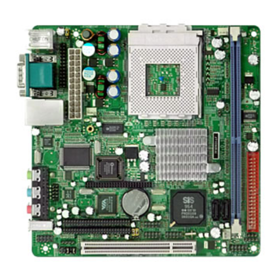
Page 7: Layout Diagram & Jumper Setting
1-3 Layout Diagram & Jumper Setting COM1 Optional IEEE 1394a PS/2 MOUSE LINE-IN PS/2 Keyboard LINE-OUT USB / KB / MS Power ON Jumper (JP1) Socket-A for AMD Geode™ NX Processor ATX Power Connector Parallel Connector CPU FAN SFAN2 PS2 KB/Mouse Port DDR333 DIMM Socket VGA / COM1... - Page 8 Jumpers Jumper Name Description Page Keyboard Power ON Function Setting 3-pin Block USB Power On Function Setting 3-pin Block CMOS RAM Clear Function Setting 3-pin Block Connectors Connector Name Description Page ATXPWR24P 24-pin ATX Power Connector 20-pin Block p.12 PS2KBS1 PS/2 Mouse &...
-
Page 9: Chapter 2 Hardware Installation
Chapter 2 Hardware installation 2-1 Hardware installation Steps Before using your computer, you had better complete the following steps: 1. Check motherboard jumper setting 2. Install CPU and Fan 3. Install System Memory (DIMM) 4. Install Expansion cards 5. Connect IDE and Floppy cables, Front Panel /Back Panel cable 6. - Page 10 (3) CMOS RAM Clear (3-pin): JP4 A battery must be used to retain the motherboard configuration in CMOS RAM short 1-2 pins of JP4 to store the CMOS data. To clear the CMOS, follow the procedure below: Turn off the system and unplug the AC power Remove ATX power cable from ATX power connector Locate JP4 and short pins 2-3 for a few seconds Return JP4 to its normal setting by shorting pins 1-2...
-
Page 11: Glossary
2-3 Glossary Chipset (core logic) - two or more integrated circuits which control the interfaces between the system processor, RAM, I/O devises, and adapter cards. Processor socket - the socket used to mount the system processor on the motherboard. Slot (AGP, PCI, ISA, RAM) - the slots used to mount adapter cards and system RAM. AGP - Accelerated Graphics Port - a high speed interface for video cards;... -
Page 12: Setting Cpu Bus Clock & Memory Clock Jumper
2-3-1 Setting CPU Bus Clock & Memory Clock Jumper Setting the front side bus frequency and SDRAM frequency The motherboard uses jumper less function for the front side bus frequency and SDRAM frequency users don’t need setting any jumper when plug the CPU in motherboard For experience user looking for over clocking possibility, please refer to sec 2-3-2. -
Page 13: Install Memory
2-4 Install Memory The motherboards provide 184-pin DUAL INLINE MEMORY MODULES (DIMM) sites for memory expansion available from minimum memory size of 64MB to maximum memory size of 1.0GB DDR2 SDRAM. Valid Memory Configurations Bank 184-Pin DIMM Total Memory Bank 0, 1 (DDR1) DDR 333/ DDR 266 64MB∼1.0GB DDR SDRAM Module... -
Page 14: Expansion Cards
2-5 Expansion Cards WARNING! Turn off your power when adding or removing expansion cards or other system components. Failure to do so may cause severe damage to both your motherboard and expansion cards. 2-5-1 Procedure For Expansion Card Installation 1. Read the documentation for your expansion card and make any necessary hardware or software setting for your expansion card such as jumpers. -
Page 15: Interrupt Request Table For This Motherboard
2-5-3 Interrupt Request Table For This Motherboard Interrupt request are shared as shown the table below: INT A INT B INT C INT D INT E INT F INT G INT H √ Slot 1 √ Onboard VGA √ Onboard USB 1 √... -
Page 16: Connectors, Headers
2-6 Connectors, Headers 2-6-1 Connectors (1) Power Connector (24-pin block) : ATXPWR24P ATX Power Supply connector. This is a new defined 24-pins connector that usually comes with ATX case. The ATX Power Supply allows to use soft power on momentary switch that connect from the front panel switch to 2-pins Power On jumper pole on the motherboard. - Page 17 RJ45 Over USB Port connector: UL1 The connectors are 4-pins connector that connect USB devices to the system board, and standard RJ45 connector for Network supports 10/100 BASE-T transfer rate. Serial Port Connector (9-pin female): VGA_COM1 Serial Port connector is a 9-pin D-Subminiature connector. The On-board Serial Port can be disabled through the BIOS SETUP.
-
Page 18: Headers
• For performance issues, we strongly suggest you don’t install a CD-ROM or DVD-ROM drive on the same IDE channel as a hard disk. Otherwise, the system performance on this channel may drop. (9) Serial-ATA Port connector: SATA1 / SATA2 This connector supports the provided Serial ATA IDE hard disk cable to connecting the motherboard and serial ATA hard disk. - Page 19 (2) Parallel Port Headers (25-pin Block): Parallel The On-board Parallel Port can be disabled through the BIOS SETUP. Please refer to Chapter 3 “INTEGRATED PERIPHERALS SETUP” section for more detail information. Pin 1 PARALLEL Connector Line-Out, MIC Header (9-pin): AUDIO This header connects to Front Panel Line-out, MIC connector with cable.
- Page 20 USB Port Headers (9-pin) : USB1/USB2/ USB3 These headers are used for connecting the additional USB port plug. By attaching an option USB cable, your can be provided with two additional USB plugs affixed to the back panel. USB1 Pin 1 USB2 USB3 Pin 1...
- Page 21 (10) Power switch: PWR BTN This 2-pin connector connects to the case-mounted power switch to power ON/OFF the system. PWRLED SPEAK SPKR Pin 1 JW FP VCC5 Pin 1 System Case Connections (11) FAN Speed Headers (3-pin) : CPUFAN, SFAN1/SFAN2 These connectors support cooling fans of 350mA (4.2 Watts) or less, depending on the fan manufacturer, the wire and plug may be different.
- Page 22 (13) Expansion Daughter Board Headers :CN1/CN2 These two Headers can add the COM Port card/ LAN card/ PCMCIA card. C N1 Pin 1 C N2 Pin 1 Expansion Daughter Board Headers (14) LVDS Headers (4-pin) : LVDS This 50 pin female header allows you connect to the LCD monitor devices LVDS Pin 1 LVDS Headers...
- Page 23 (15) Optional Expansion cards: Expansion Daughter-boards (optional) For 2xCOM Ports Added For 4xCOM Port Added Card Bus Type I + II Supported Expansion IDE Interface Supported CF Compatible Interface With CF Compatible Card Reader Disk On Module For 2 or 2 10/100 or -Extended D-Sub 15-pin and DVI Connectors 10/100/1000 Ethernet LAN...
-
Page 24: Starting Up Your Computer
2-7 Starting Up Your Computer 1. After all connections are made, close your computer case cover. 2. Be sure all the switch are off, and check that the power supply input voltage is set to proper position, usually in-put voltage is 220V∼240V or 110V∼120V depending on your country’s voltage used. -
Page 25: Chapter 3 Introducing Bios
Chapter 3 Introducing BIOS The BIOS is a program located on a Flash Memory on the motherboard. This program is a bridge between motherboard and operating system. When you start the computer, the BIOS program gain control. The BIOS first operates an auto-diagnostic test called POST (power on self test) for all the necessary hardware, it detects the entire hardware device and configures the parameters of the hardware synchronization. -
Page 26: The Main Menu
3-3 The Main Menu Once you enter Award ® BIOS CMOS Setup Utility, the Main Menu (Figure 3-1) will appear on the screen. The Main Menu allows you to select from fourteen setup functions and two exit choices. Use arrow keys to select among the items and press <Enter> to accept or enter the sub-menu. -
Page 27: Standard Cmos Features
Save & Exit Setup Save CMOS value changes to CMOS and exit setup. Exit Without Saving Abandon all CMOS value changes and exit setup. 3-4 Standard CMOS Features The items in Standard CMOS Setup Menu are divided into several categories. Each category includes no, one or more than one setup items. -
Page 28: Advanced Bios Features
3-5 Advanced BIOS Features Phoenix – AwardBIOS CMOS Setup Utility Advanced BIOS Features Virus Warning Disabled Item Help CPU Internal Cache Enabled External Cache Enabled Quick Power On Self Test Enabled Menu Level > Hard Disk Boot Priority Press Enter First Boot Device Floppy Second Boot Device... -
Page 29: Advanced Chipset Features
Gate A20 Option Normal The A20 signal is controlled by keyboard controller or chipset hardware. Fast (default) The A20 signal is controlled by port 92 or chipset specific method. Typematic Rate Setting Keystrokes repeat at a rate determined by the keyboard controller. When enabled, the typematic rate and typematic delay can be selected. -
Page 30: Dram Timing Setting
DRAM Timing Setting Please refer to section 3-6-1 AGP and P2P Bridge Control The selection allows you to modify the AGP bus related settings and functions for better graphics performance. System BIOS Cacheable Selecting Enabled allows caching of the system BIOS ROM at F0000h-FFFFFh, resulting in better system performance. -
Page 31: Agp Timing Settings
3-6-2 AGP Timing Settings Phoenix – AwardBIOS CMOS Setup Utility AGP Timing Settings AGP Data Transfer Rate Auto Item Help Menu Level >> ↑↓→← Move Enter:Select +/-/PU/PD:Value F10:Save ESC:Exit F1:General Help F5:Previous Values F6:Optimized Defaults F7:Standard Defaults AGP Data Transfer Rate To define the AGP bus data transfer Rate for your system, and the default setting is “AUTO”. -
Page 32: Integrated Peripherals
3-7 Integrated Peripherals Phoenix – AwardBIOS CMOS Setup Utility Integrated Peripherals OnChip IDE Function Press Enter Item Help OnChip Device Function Press Enter OnChip SIO Function Press Enter Init Display First PCI Slot Menu Level > ↑↓→← Move Enter:Select Item +/-/PU/PD:Value F10:Save ESC:Exit F1:General Help F5:Previous Values F6:Optimized Defaults... -
Page 33: Onchip Device Function
Primary Master/Slave PIO The two IDE PIO (Programmed Input/Output) fields let you set a PIO mode (0-2) for each of the two IDE devices that the onboard IDE interface supports. Modes 0 through 2 provide successively increased performance. In Auto mode, the system automatically determines the best mode for each device. -
Page 34: Onboard Super Io Function
3-7-3 Onboard Super IO Function Phoenix – AwardBIOS CMOS Setup Utility Onboard Super IO Function Onboard FDD Controller Enabled Item Help Onboard Serial Port 1 3F8/IRQ4 Onboard Serial Port 2 2F8/IRQ3 VART Mode Select Normal Menu Level >> Onboard Parallel Port 378/IRQ7 Parallel Port Mode ECP Mode Use DMA... -
Page 35: Power Management Setup
3-8 Power Management Setup The Power Management Setup allows you to configure your system to most effectively save energy saving while operating in a manner consistent with your own style of computer use. Phoenix – AwardBIOS CMOS Setup Utility Power Management Setup ACPI Function Enabled... -
Page 36: Wake Up Events
3-8-1 Wake Up Events Phoenix – AwardBIOS CMOS Setup Utility Wake Up Events IRQ [3-7,9-15] Enabled Item Help IRQ 8 Break Suspend Disabled Ring Power Up Control Disabled MACPME Power Up Control Disabled Menu Level >> PCPME Power Up Control Disabled PS2KB Power Up Control Disabled... -
Page 37: Pnp/Pci Configuration Setup
3-9 PnP/PCI Configuration Setup This section describes configuring the PCI bus system. PCI, or Personal Computer Interconnect, is a system which allows I/O devices to operate at speeds nearing the speed the CPU itself uses when communicating with its own special components. This section covers some very technical items and it is strongly recommended that only experienced users should make any changes to the default settings. -
Page 38: Pc Health Status
3-10 PC Health Status This section shows the Status of you CPU, Fan, Warning for overall system status. This is only available if there is Hardware Monitor onboard. Phoenix – AwardBIOS CMOS Setup Utility PC Health Status Item Help Shutdown Temperature Disabled Show PC Healthy in Post Enabled... -
Page 39: Load Standard/Optimized Defaults
3-12 Load Standard/Optimized Defaults Load Standard Defaults When you press <Enter> on this item, you get confirmation dialog box with a message similar Load Standard Defaults (Y/N)? N Pressing <Y> loads the BIOS default values for the most stable, minimal-performance system operations. -
Page 40: Chapter 4 Driver & Free Program Installation
Chapter 4 DRIVER & FREE PROGRAM INSTALLATION Check your package and there is A MAGIC INSTALL CD included. This CD consists of all DRIVERS you need and some free application programs and utility programs. In addition, this CD also include an auto detect software which can tell you which hardware is installed, and which DRIVERS needed so that your system can function properly. -
Page 41: Agpxd Install Sis Agpxd Driver
4-1 AGPXD Install SiS AGPXD Driver The AGPVXD Driver is Only For AGP Slot VGA CARD User, before install AGP card driver please install this AGPVXD driver first. The path of the file: for WINDOWS 9X/2000/XP is X:\SIS\AGPVXD\SETUP.EXE 1. Click AGPVXD when Magic Install MENU 2. -
Page 42: Ide Install Sis Mini Idedriver
4-2 IDE Install SiS MINI IDE Driver For WINDOWS 9X/ME/NT4.0/2000/XP 1. Click IDE when Magic Install main menu Select appropriate language you want to appears install then click OK 3. Click FINISH and Restart Computer... -
Page 43: Vga Install Sis Mirage Vga Driver
4-3 VGA Install SiS Mirage VGA Driver 1. Click VGA when MAGIC INSTALL MENU 2. Click Next when SiS Compatible Multimedia appears Package appears 3. Multimedia Package supports three types of 4. System will add program icons to the Program Setup: Typical, Compact, Custom Please Files. -
Page 44: Sound Install Alc Ac'97 Codec Audio Driver
4-4 SOUND Install ALC AC97’ Codec Audio Driver 3. Click SOUND when MAGIC INSTALL 4. Click NEXT when the Realtek AC97 Audio MENU appears Setup windows appear 3. Click Finish and Restart Windows 4. Realtek AVRACK utility 5. Sound Effect select and KaraOK Mode 6. -
Page 45: Lan Install Realtek Lan Controller Driver
4-5 LAN Install Realtek LAN Controller Driver The VIA 10/100Mb PCI Ethernet Adapter Driver path is X:\VIA\LANDRV 1. Click LAN when Magic Install Menu appear Click NEXT, install REALTEK LAN and Fast Ethernet NIC Driver 3. After driver installation completed, Click Finish 4-6 USB2.0 Install SiS USB2.0 DEVICE DRIVER... - Page 46 4-7 PC-CILLIN Install PC-CILLIN 2006 Anti-virus program Click PC-CILLIN when MAGIC INSTALL Please select “Install program” when the MENU appears "Trend Micro internet security" installshield wizard windows appears This is license agreement, select "I Accept Click NEXT or choose Change to change the the terms"...
-
Page 47: Pc-Health Install Myguard Hardware Monitor Utility
PC-HEALTH Install MyGuard Hardware monitor Utility 1. Click PC-HEALTH when MAGIC INSTALL 2. Click Next when Install shield wizard Window MENU appears appears, Choose destination location and click Next, when the start copy file windows appear, click next 3. Select Finish after setup complete 4. -
Page 48: How To Disable On-Board Sound
4-9 HOW TO DISABLE ON-BOARD SOUND Enter BIOS SETUP choose INTEGRATE PERIPHERALS choose ON-CHIP DEVICE FUNCTION choose AC97 AUDIO Disable on-board sound function by press PAGE DOWN KEY to Disable 4-10 HOW TO UPDATE BIOS Before update BIOS users have to “Disable”, “Flash Part Write Protect” item which in “Miscellaneous Control”...