Advertisement
Quick Links
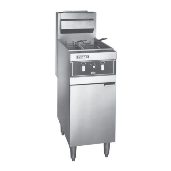
GRS, GRD, AND GRC 25, 35, 45, 65
AND 85 MODEL FRYERS
MODEL
ML-52077
ML-52078
ML-52079
ML-52080
ML-52081
ML-52082
ML-52306
ML-52307
ML-52139
ML-52308
V U L C A N - H A R T C O M P A N Y , P . O . B O X 6 9 6 , L O U I S V I L L E , K Y 4 0 2 0 1 - 0 6 9 6 , TEL. (502) 7 7 8 - 2 7 9 1
FORM 30912 (1-95)
SERVICE MANUAL
MODEL GRD35
Advertisement

Related Manuals for Vulcan-Hart GRS25


Summary of Contents for Vulcan-Hart GRS25
- Page 1 SERVICE MANUAL GRS, GRD, AND GRC 25, 35, 45, 65 AND 85 MODEL FRYERS MODEL ML-52077 ML-52078 ML-52079 ML-52080 ML-52081 ML-52082 ML-52306 ML-52307 ML-52139 ML-52308 MODEL GRD35 V U L C A N - H A R T C O M P A N Y , P . O . B O X 6 9 6 , L O U I S V I L L E , K Y 4 0 2 0 1 - 0 6 9 6 , TEL. (502) 7 7 8 - 2 7 9 1 FORM 30912 (1-95)
-
Page 2: Important For Your Safety
IMPORTANT FOR YOUR SAFETY THIS MANUAL HAS BEEN PREPARED FOR PERSONNEL QUALIFIED TO SERVICE AND ADJUST THE EQUIPMENT COVERED BY THIS MANUAL. POST IN A PROMINENT LOCATION THE INSTRUCTIONS TO BE FOLLOWED IN THE EVENT THE SMELL OF GAS IS DETECTED. THIS INFORMATION CAN BE OBTAINED FROM THE LOCAL GAS SUPPLIER. -
Page 3: Codes And Standards
Pages 61-109 CODES AND STANDARDS Vulcan-Hart Fryers are to be installed in accordance with state and local codes, or in the absence of local codes, the National Fuel Gas Code, ANSI-Z223.1(latest edition), available from the American Gas Association, Inc., 1515 Wilson Boulevard, Arlington, VA. 22209 and with ANSI-NFPA Standard #96 (latest edition), Vapor Removal From Cooking Equipment, available from the National Fire Protection Association, Batterymarch Park, Quincy, MA 02269. - Page 4 SECTION I GRS,GRD AND GRC SERVICE CHECKS & ADJUSTMENTS WARNING: UNPLUG FRYER BEFORE SERVICING. WARNING: SHUT OFF GAS BEFORE SERVICING. WARNING: CERTAIN PROCEDURES IN THIS SECTION REQUIRE ELECTRICAL TEST OR MEASUREMENTS WHILE POWER IS APPLIED TO THE FRYER. EXERCISE EXTREME CAUTION AT ALL TIMES.
- Page 5 COMBINATION VALVE GAS PRESSURE CHECK 1. Check pressure rating of appliance as stated on the fryer door. 2. Connect a manometer to the pressure tap of the gas combination valve (gas tap is marked on valve). 3. Turn on all appliance burners. 4.
- Page 6 HI LIMIT CHECK 1. Place pyrometer in the tank 1/2" above the crumb screen in the center of the vat. 2. Turn fryer on. 3. Bypass the hi limit by running a jumper wire between pins 13 and 14 on the temperature board. Run the appliance temperature up to between 465-470 degrees F.
- Page 7 FILTER INTER PLUMB DISCARD TUBE (Option) 1. Close the drain valve. 2. Place shortening discard pan under the tube plug end that will be serviced. 3. With a pipe wrench open the plugged end of the tube up. 4. Insert the clean-out rod supplied with the fryer into the opening. 5.
- Page 8 SECTION I GRS SERIES (ONLY) SERVICE CHECKS WARNING: UNPLUG FRYER BEFORE SERVICING. WARNING: SHUT OFF GAS BEFORE SERVICING. WARNING: CERTAIN PROCEDURES IN THIS SECTION REQUIRE ELECTRICAL TEST OR MEASUREMENTS WHILE POWER IS APPLIED TO THE FRYER. EXERCISE EXTREME CAUTION AT ALL TIMES. IF TEST POINTS ARE NOT EASILY ACCESSIBLE, DISCONNECT POWER, ATTACH TEST EQUIPMENT AND REAPPLY POWER TO TEST.
- Page 9 SECTION I GRD AND GRC SERIES (ONLY) SERVICE CHECKS 1 2 3 4 5 6 7 24V 24V W MV PV PV GND GNDHOT TH WARNING: UNPLUG FRYER BEFORE SERVICING. WARNING: SHUT OFF GAS BEFORE SERVICING. WARNING: CERTAIN PROCEDURES IN THIS SECTION REQUIRE ELECTRICAL TEST OR MEASUREMENTS WHILE POWER IS APPLIED TO THE FRYER.
- Page 10 3. Push power switch ON and immediately touch one end of the jumper firmly to the GND terminal on the module. Do not touch the jumper to the SPARK terminal, but, move the free end of the jumper slowly towards the SPARK terminal until a spark is established.
- Page 11 SERVICE MODE Enter the service mode by pressing the product 3 and product 4 keys while turning "on" power to the fryer computer. Display should now read "SERVICE". In this mode the following display/systems response will be given for the noted error condition. SYSTEMS PROBLEM DISPLAY SYSTEMS RESPONSE...
- Page 12 SECTION II REMOVAL OF CONTROL PANEL AND REPLACEMENT OF CONTROLS WARNING: UNPLUG FRYER BEFORE SERVICING. WARNING: SHUT OFF GAS BEFORE SERVICING. WARNING: CERTAIN PROCEDURES IN THIS SECTION REQUIRE ELECTRICAL TEST OR MEASUREMENTS WHILE POWER IS APPLIED TO THE FRYER. EXERCISE EXTREME CAUTION AT ALL TIMES.
- Page 13 4. Reinstall panel by reversing steps 1-3. CONTROL PANEL (ELECTRONIC IGNITION) 1. Follow steps 1 through 3 under Standard Millivolt Construction. (Fig. 3) 2. Disconnect basket lift (applicable) or main wire harness before removing the control panel and fryer door. Fig.
- Page 14 CONTROL PANEL (COMPUTERIZED). 1. Follow steps 1 through 2 under Solid State Construction and disconnect the computer power wiring harness. (Figs. 5) Figs. 5 2. To remove the computer disengage (6) 6-32 nuts from the back of the control panel. (Fig. 6) Fig.
- Page 15 REMOVAL OF CONTROL PANEL HOUSING 1. Follow steps 1-2 under Control Panel (Electronic ignition). 2. With a 5/16" socket remove (4) screws holding the housing to the fryer body sides. (Fig. 7) Fig. 7 3. Note and disconnect any wiring harnesses from the housing. If millivolt fryer, pull the thermostat wire through the access hole in the box.
- Page 16 REMOVAL OF KX THERMOSTAT 1. Drain fry compound from the tank. 2. Follow steps 1-3 under Removal of Control Panel (Standard Millivolts) (Figs. 9) 3. Remove (2) wires from the thermostat. Figs. 9 5. From inside tank remove (4) #8 screws using a 1/4" socket to disassemble the thermostat bulb and hi limit clamps.
- Page 17 5. From inside the fryer cabinet, follow the thermostat lead wire to the bulb packing nuts in the bottom of the tank. With a 5/16" wrench remove the thermostat packing nut and with an 11/16" wrench remove the thermostat bulb holding nut. (Fig.11) Holding Nut Packing Nut Fig.
- Page 18 REMOVAL OF POTENTIOMETER 1. Follow steps 1-2 under Control Panel (Solid State Construction) 2. With a small flat blade screwdriver loosen the set screw in the potentiometer knob. (Fig. 13) Set Screw Fig. 13 3. Pull the knob off of the panel. 4.
- Page 19 REMOVAL OF THERMISTOR PROBE 1. Follow steps 1-5 under Removal of Potentiometer. 2. If necessary remove burners that may be in the way of the thermistor probe hardware in the bottom of the fryer tank. Refer to Removal of Burner. 3.
- Page 20 5. Pull the thermistor probe lead from the fryer tank and install new Thermistor probe by reversing steps 1-6. (See Fig. 12) REMOVAL OF COMPUTER 1. Follow steps 1-2 under Control Panel (Computerized) 2. Make sure all wire harnesses are disconnected. Remove (6) screw securing the computer to the panel with a 1/4"...
- Page 21 REMOVAL OF ROCKER SWITCHES 1. Follow steps 1-2 under Control Panel (Solid State). 2. From rear of control panel note and remove wire leads from the rocker switch terminals. (Fig. 19) Fig. 19 3. Press tabs on both sides of the switch and push the switch through the front of the control panel. (Fig. 20) Fig.
- Page 22 REMOVAL OF HIGH LIMIT 1. Drain shortening from the fryer. 2. Open fryer door and disengage hi limit wire harness located below the control housing to the left side of the fryer. (Fig. 21) Fig. 21 3. With a flat blade screwdriver note and remove (3) wire leads from the high limit. (Fig. 22) Fig.
- Page 23 4. Remove (2) #8 sheet metal screws from the bracket holding the limit in place. (Fig.23) Fig. 23 From inside the fryer tank, with a 1/4" socket remove (4) #8 screws and holding brackets for the limit bulb. (Fig. 24) Fig.
- Page 24 6. If necessary for ease of accessibility follow steps 1-8 under Removal of Burner and take out any burner in the way of the limit bulb packing and retaining nuts. 7. With a 5/16" wrench remove the limit packing nut from the tank bottom. (Fig. 25) Fig.
- Page 25 9. Pull the limit bulb out from underneath the fryer tank. (See Fig. 86) 10. Reinstall new high limit by reversing steps 1-9. REMOVAL OF THERMOPILE (STANDARD MILLIVOLT SYSTEM) 1. Follow steps 1- 3 under Control Panel (Standard Millivolt Construction) 2.
- Page 26 4. Refer to steps 1-8 under removal of burner and remove burners as required to access the thermopile bracket and its hardware. 5. Slide the control housing heat shield down. (Fig. 29) Fig. 29 6. With a 1/2" wrench remove the pilot tubing from the pilot assembly. (Fig. 30) Fig.
- Page 27 7. With an offset flat blade screwdriver remove the pilot assembly from the mounting bracket. (Fig. 31) Fig. 31 8. With a 1/2" wrench remove the thermopile from the pilot assembly. (Fig. 32) Fig. 32 9. Reinstall new thermopile by reversing steps 1-8.
- Page 28 REMOVAL OF PILOT 1. Follow instructions for the Removal of Thermopile. 2. With a 1/2" wrench remove the hex nut on the bottom of the pilot and disconnect the pilot tube. (Figs. 33) 3. With an offset flat blade screwdriver remove the pilot assembly bracket from the fryer. (Figs. 33) Figs.
- Page 29 Figs. 34 3. Refer to steps 1-8 under Removal of Burners and disassemble burners as required to access the ignitor assembly for servicing. 4. Slide the control housing heat shield down. (Fig. 29) 5. Remove the ignitor boot. (Fig. 35) Fig.
- Page 30 REMOVAL OF GAS COMBO VALVE 1. Shut off all gas and electrical power to the unit. 2. Open fryer door and locate valve. (Fig. 36) Fig. 36 3. Follow steps 1-8 under the Removal of Burners and disassemble any burner obstructing your working area for the combo valve.
- Page 31 The next several steps may require the removal of the Discard drain tubes on fryers with filtering systems. If this applies to the fryer being serviced refer to steps 1-7 under Removal of Filter Discard Tubes. 6. With a 3/4" wrench remove the gas line compression elbow fitting. (Fig. 38) Fig.
- Page 32 8. Note and remove any old fittings left on the valve. Keep them for reassembly to the new valve. 9. Install the old fittings removed in step 8 to the new valve. 10. Install the new valve by reversing steps 1- 7. 11.
- Page 33 5. With a 1/2" socket loosen (2) bolts that attach the burner to the mounting frame. (Fig. 41) Fig. 41 6. Slide the heat shield back up to its original position. 7. If the fryer is equipped for filtering the discard tube(s) may need to be disconnect at this point. Refer to steps 1-7 under Removal of Discard Tube(s).
- Page 34 BULLET NOSE BURNER ORIFICE REPLACEMENT 1. Follow steps 1-8 under Replacement of Burner. 2. Disconnect the burner orifice top from bullet with a 5/16" wrench. The bullet body may be removed with channel locks. (Figs. 43) Figs. 43 3. Install new orifice by reversing steps 1-2. REMOVAL OF FILTER DISCARD TUBE(S) (FILTER INTER PLUMB BATTERY FRYERS) 1.
- Page 35 4. Separate the discard tube by sliding the rubber collar down one side of the drain tube. (Fig. 45) Rubber Collar Fig. 45 5. Move the discard pan under the ball valve. 6. With the 7/16" socket remove the clamp hardware securing the tube to the ball valve assembly. Also if the tube/extension section is located at the end of a battery to facilitate an RO Frymate using a 5/16"...
- Page 36 REMOVAL OF POWER SUPPLY BOX (ELECTRONIC IGNITION AND BASKET LIFT MODELS) 1. Disconnect gas line and pull out so that the back is accessible. 2. Disconnect the supply box wire harness (Fig. 47) Fig. 47 3. From the front of the unit follow steps 1-5 under Removal of ignitor assembly. 4.
- Page 37 5. Drop the supply box housing out of the bottom of the fryer. 6. To access the controls with a 5/16" socket remove (2) screws from the power supply box top cover. (Fig. 49) 7. Reinstall housing by reversing steps 1-6. REMOVAL OF IGNITOR MODULE 1.
- Page 38 5. With a 1/4" socket remove (4) #8 sheet metal screws and pull module from the housing. (Fig. 51) Fig. 51 6. Reinstall new module by reversing steps 1- 5. REMOVAL OF TRANSFORMER 1. Follow steps 1- 6 for the Removal of the Supply Box Housing 2.
- Page 39 4. With 1/4" socket remove (2) screws securing the transformer to the control box. (Fig. 53) Fig. 53 5. Install new transformer by reversing steps 1-4. REMOVAL OF ELECTRICAL SUPPLY CORD Note: The power supply line for a fryer with filter inter plumb is located in the rear of appliance housed in a junction box.
- Page 40 4. From inside the box disconnect wiring associated with the supply cord. 5. Install the new power supply cord by reversing steps 1-4. REMOVAL OF BASKET LIFT BACK (OPTIONAL ACCESSORIES) 1. Remove all baskets and basket support racks from tank. 2.
- Page 41 5. Lift back up and over the lift mechanism. (Fig. 57) Fig. 57 6. Disconnect the gas line and remove the lower basket lift back by disengaging (2) screws at each lower side of the cover and (2) screws from each lower back corner using a 1/4" socket. (Fig. 58) Fig.
- Page 42 7. To reinstall basket back panels reverse steps 1-6. REMOVAL OF LIFT ROD MECHANISM 1. Follow steps 1-6 under Removal of Basket Lift Backs 2. With a 1/2" wrench remove the nut that attaches the lift rod to the lift bar. (Fig. 59) Fig.
- Page 43 4. With 5/16" socket remove (2) nut holding the cam lift bracket to the fryer back. (Fig. 61) Fig. 61 5. Remove motor wiring. (Fig. 62) Fig. 62...
- Page 44 6. With flat blade screwdriver remove (2) screws holding the motor to the cam bracket assembly. (Fig. 63) Fig. 63 7. Remove the motor from the cooker. To install new motor reverse steps 1-6. 8. Make certain that all wiring is clear from motor cam shaft (wire ties may be required). REMOVAL OF BASKET LIFT CAM SWITCH (OPTIONAL ACCESSORY) 1.
- Page 45 REMOVAL OF BASKET LIFT CAM (OPTIONAL ACCESSORY) 1. Follow steps 1-6 under Removal of Basket Lift Back. 2. With a 1/2" wrench or socket remove the lift bar and cam assembly holding nut. (Fig. 65) Fig. 65 3. With an allen wrench loosen the cam set screw. (Fig. 66) Fig.
- Page 46 REMOVAL OF TANK ASSEMBLY If the fryer is equipped with automatic basket lifts the lift arm(s) must be removed from the fryer back before the tank can be removed. 1. Remove fryer baskets and crumb screen. (Figs. 67) Figs. 67 2.
- Page 47 3. If a fryer battery is involved, with a utility knife split the silicon sealant from around the grease strip between the tanks and remove the stainless grease strip, then split the tank sections apart with a utility knife (Fig. 69) Fig.
- Page 48 5. Follow steps 1-4 under Removal of Control Housing. 6. Follow steps 1-7 under Removal of Discard Tube(s). 7. For D and C models with a 7/16" socket and wrench remove (2) nuts from under base frame that secure the manifold assembly to the frame.
- Page 49 9. With a 13/16" wrench disconnect the compression elbow from the gas inlet tube. (Fig. 73) Fig. 73 10. With 5/16" remove (4) screws holding the heat shield in place. (See Fig. 48) 11. Slide the heat shield down. (See Fig. 48) 12.
- Page 50 13. Disconnect micro switch. (Fig. 75) Fig. 75 14. With a 13/16" wrench disconnect the oil refill coupling. (Fig. 76) Fig. 76...
- Page 51 15. Grasp tank from the back at the top of the flue wrap area and lift the entire tank assembly out of the fryer body. Note that on D and C models the heat shield insulation may catch on the body frame. If this occurs the tank assembly will not lift out of the unit.
- Page 52 17. Remove the burner insulation box. (Fig. 79) Fig. 79 18. With flat blade screwdriver remove the pilot bracket. (Fig. 80) Fig. 80...
- Page 53 19. If servicing a D or C model with a 5/16" wrench remove the hi limit packing nut. For S models use a 1/2" wrench. (Fig. 81) Fig. 81 20. With an 11/16" wrench remove the compression nut securing the limit bulb to the tank. (Fig. 82) Fig.
- Page 54 21. With an 1/2" wrench remove the thermistor or thermo bulb packing nut. (Fig. 83) Fig. 83 22. With an 11/16" wrench remove the compression nut holding the thermistor or thermo bulb to the tank. (Fig. 84) Fig. 84...
- Page 55 23. With a 1/4" socket from inside the fryer tank remove the hardware and mounting clips holding the hi limit and thermistor/thermostat bulb to the tank. (Figs. 85) Figs. 85 24. Pull both the termistor and hi limit probes through the tank bottom and remove them from the fryer.
- Page 56 25. With a 1/2" wrench remove (4) bolts securing the manifold bracket to the tank assembly. (Fig. 87) Fig. 87 26. For fryers housing a filter station with a quick disconnect from the front of unit with a 7/16" socket and wrench remove the "U"...
- Page 57 27. Remove the pull rod handle. (Fig. 89) Fig. 89 28. With a 7/16" socket remove all the pull rod hardware from the micro switch assembly. (Fig. 90) Fig. 90...
- Page 58 29. Pull the rod up through the mounting bracket and out of the fryer. (Fig. 91) Fig. 91 30. Pull the manifold assembly from the fryer. (Fig. 92) Fig. 92...
- Page 59 31. With an adjustable wrench remove the elbow from the tank assembly. (Fig. 93) Fig. 93 32. With a 3/8" socket remove (2) nuts holding the oil return line to the tank assembly. (Figs. 94) Figs. 94...
- Page 60 33. With a pipe wrench remove the remove the drain valve and drain pipe assembly from the tank. (Fig 95) Fig. 95 34. With a 3/8" socket remove (4) screws securing the flue box to the tank assembly. (Fig. 96) Fig.
- Page 61 SECTION lll WIRING INFORMATION...
- Page 62 Drwg. No. 419357-1...
- Page 64 Drwg. No. 419357-2...
- Page 66 Drwg. No. 419357-3...
- Page 68 Drwg. No. 419322-1...
- Page 70 Drwg. No. 419322-2...
- Page 72 Drwg. No. 419322-3...
- Page 74 Drwg. No. 419323-1...
- Page 76 Drwg. No. 419323-2...
- Page 78 Drwg. No. 419323-3...
- Page 80 Drwg. No. 419318-1...
- Page 82 Drwg. No. 419318-2...
- Page 84 Drwg. No. 419318-3...
- Page 86 Drwg. No. 419340-1...
- Page 88 Drwg. No. 419340-2...
- Page 90 Drwg. No. 419340-3...
- Page 92 Drwg. No. 419337-1...
- Page 94 Drwg. No. 419337-2...
- Page 96 Drwg. No. 419337-3...
- Page 98 Drwg. No. 419564-1...
- Page 100 Drwg. No. 419564-2...
- Page 102 Drwg. No. 419564-3...
- Page 104 Drwg. No. 419366-1...
- Page 106 Drwg. No. 419366-2...
- Page 108 Drwg. No. 419366-3...
- Page 112 FORM 30912 (1-95)