Table of Contents
Advertisement
Quick Links
For additional information on Vulcan-Hart or to locate an authorized parts
and service provider in your area, visit our website at www.vulcanhart.com
VULCAN-HART
DIVISION OF ITW FOOD EQUIPMENT GROUP, LLC
WWW.VULCANHART.COM
This manual is prepared for the use of trained Vulcan Service
Technicians and should not be used by those not properly
qualified. If you have attended a Vulcan Service School for this
product, you may be qualified to perform all the procedures
described in this manual.
This manual is not intended to be all encompassing. If you have
not attended a Vulcan Service School for this product, you
should read, in it's entirety, the repair procedure you wish to
perform to determine if you have the necessary tools, instruments
and skills required to perform the procedure. Procedures for
which you do not have the necessary tools, instruments and
skills should be performed by a trained Vulcan Service
Technician.
Reproduction or other use of this Manual, without the express
written consent of Vulcan, is prohibited.
SERVICE MANUAL
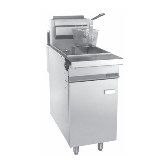
GHF SERIES HEAVY DUTY
RANGE MATCHING GAS
FRYERS & FRYMATES
MODELS
GHF91G
GHF90G
- NOTICE -
P.O. BOX 696, LOUISVILLE, KY 40201-0696
– 1 –
ML-135503
ML-135504
TEL. (502) 778-2791
FORM 35618 (11-04)
Advertisement
Table of Contents

Related Manuals for Vulcan-Hart GHF90G


Summary of Contents for Vulcan-Hart GHF90G
- Page 1 Technician. Reproduction or other use of this Manual, without the express written consent of Vulcan, is prohibited. For additional information on Vulcan-Hart or to locate an authorized parts and service provider in your area, visit our website at www.vulcanhart.com VULCAN-HART DIVISION OF ITW FOOD EQUIPMENT GROUP, LLC WWW.VULCANHART.COM...
-
Page 2: Table Of Contents
Nozzles and Orifices ... 10 Combination Valve Regulator Adjustment ... 11 ELECTRICAL OPERATION ...12 Control System Description ...12 System Condition Quick Check Procedures ... 12 Schematic ... 13 Component Function ... 13 TROUBLESHOOTING ...14 © VULCAN-HART, 2004 TABLE OF CONTENTS – 2 –... -
Page 3: General
INTRODUCTION Models This service manual was written for: GHF91G Gas Fryers and GHF90G Gas Frymates. INSTALLATION Generally, installations are made by the dealer or contracted by the dealer or owner. Detailed installation instructions are included in the Installation and Operation Manual, which is sent with each fryer. -
Page 4: Removal And Replacement Of Parts
REMOVAL AND REPLACEMENT OF PARTS COVERS AND PANELS WARNING: SHUT OFF THE GAS BEFORE SERVICING. Door 1. Open door and using a remove (2) screws securing the top door mounting bracket to the left body side channel. 2. Hold door in one hand and lift the door panel assembly off of the bottom hinge. -
Page 5: Thermostat
THERMOSTAT WARNING: SHUT OFF THE GAS BEFORE SERVICING. 1. Drain shortening from fry tank. 2. Remove left burner as outlined under Burners. 3. Remove thermostat knob by pulling knob off thermostat shaft. 4. Remove thermostat mounting screws and remove thermostat from mounting bracket. 5. -
Page 6: High Limit
HIGH LIMIT WARNING: SHUT OFF THE GAS BEFORE SERVICING. 1. Drain shortening from fry tank. 2. Remove wire leads from high limit, noting all connections for reassembly. 3. Remove high limit from mounting bracket. 4. Remove left burner as outlined under Burners. 5. -
Page 7: Pilot Orifice
6. Remove thermopile from pilot bracket. 7. Reverse procedure to install. PILOT ORIFICE WARNING: SHUT OFF THE GAS BEFORE SERVICING. WARNING: ALL GAS JOINTS DISTURBED DURING SERVICING MUST BE CHECKED FOR LEAKS. CHECK WITH SOAP AND WATER SOLUTION (BUBBLES). DO NOT USE AN OPEN FLAME. 1. -
Page 8: Fry Tank
FRY TANK WARNING: SHUT OFF THE GAS BEFORE SERVICING. WARNING: ALL GAS JOINTS DISTURBED DURING SERVICING MUST BE CHECKED FOR LEAKS. CHECK WITH SOAP AND WATER SOLUTION (BUBBLES). DO NOT USE AN OPEN FLAME. 1. Disconnect fryer from main gas supply. 2. -
Page 9: Service Procedures And Adjustments
SERVICE PROCEDURES AND ADJUSTMENTS MILLIVOLT CONTROLS TEST 1. Verify proper gas (natural or propane) is present. 2. Check for correct wiring and secure connections. 3. Verify the pilot flame is adjusted properly as outlined in Pilot Adjustment. 4. If the pilot is not lit, light pilot as outlined under Lighting Pilot. -
Page 10: Pilot Adjustment
5. Allow temperature to stabilize at new setting and compare temperature tester to dial setting. Recalibrate if the temperature does not fall within the range of 330°F to 370°F. 6. If the temperature does not fall within the limits at both settings, replace the thermostat. PILOT ADJUSTMENT 1. -
Page 11: Combination Valve Regulator Adjustment
COMBINATION VALVE REGULATOR ADJUSTMENT WARNING: SHUT OFF THE GAS BEFORE SERVICING. Accurate gas pressure adjustments can only be made with the gas on and the burner lit. If the incoming line pressure to the valve is less than the minimum stated, then the pressure cannot be set correctly. -
Page 12: Electrical Operation
ELECTRICAL OPERATION CONTROL SYSTEM DESCRIPTION 1. The thermopile (TP) provides the total control voltage for this system. A. One side of the thermopile is connected to the common (C) of the high limit (HL). B. The other side of the thermopile is connected to the normally open (NO) contacts of the high limit. -
Page 13: Schematic
SCHEMATIC COMPONENT FUNCTION Thermostat - Millivolt type with capillary bulb, single-throw break on temperature rise. Temperature range of 200°F to 400°F. Thermopile - Millivolt control with 24" capillary. Rated to generate 500 millivolts. Combination Valve - Regulates gas flow to burner and pilot. Provides pilot safety. Hi-Limit - Prevents overheating of fryer in the event of thermostat failure. -
Page 14: Troubleshooting
TROUBLESHOOTING SYMPTOM 1. The temperature of the shortening drops, or excessive recovery time is required. 2. Pilot won't stay lit. Fryer shut off. 3. Rapid shortening breakdown, crumbs and specks in frying compound. POSSIBLE CAUSE A. Insufficient gas supply to unit. B. - Page 15 TROUBLESHOOTING SYMPTOM 4. Leaking tank. 5. Pilot burner flames adjusted properly, but fluctuate to very low and blow out easily. POSSIBLE CAUSE A. Foam-over by depleted shortening permits oil to drip from the tank surface, giving the appearance of leaking. B.
- Page 16 NOTES – 16 – FORM 35618 (11-04) PRINTED IN U.S.A.