Table of Contents
Advertisement
Quick Links
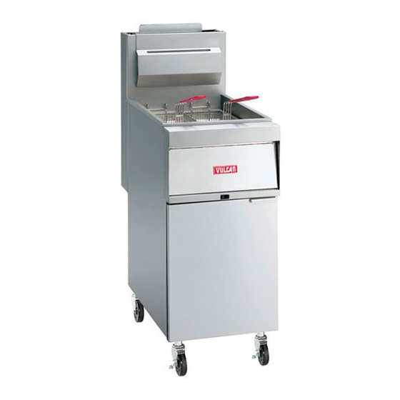
GR35 SHOWN
This Manual is prepared for the use of trained Vulcan Service
Technicians and should not be used by those not properly
qualified. If you have attended a Vulcan Service School for this
product, you may be qualified to perform all the procedures
described in this manual.
This manual is not intended to be all encompassing. If you have
not attended a Vulcan Service School for this product, you should
read, in its entirety, the repair procedure you wish to perform to
determine if you have the necessary tools, instruments and skills
required to perform the procedure. Procedures for which you do
not have the necessary tools, instruments and skills should be
performed by a trained Vulcan Service Technician.
Reproduction or other use of this Manual, without the express
written consent of Vulcan, is prohibited.
For additional information on Vulcan-Hart Company or to locate an authorized parts
and service provider in your area, visit our website at www.vulcanhart.com.
A product of VULCAN-HART
SERVICE MANUAL
GR SERIES GAS FRYERS WITH
MILLIVOLT CONTROLS
MODEL
GR25
GR35
GR45
GR65
GR85
- NOTICE -
ML
MODEL
126988
GR35F
126989
GR45F
126990
GR65F
126991
GR85F
126992
LOUISVILLE, KY 40201-0696
F25125 (March 2003)
ML
126998
126999
135534
135535
Advertisement
Table of Contents

Related Manuals for Vulcan-Hart GR25


Summary of Contents for Vulcan-Hart GR25
-
Page 1: Millivolt Controls
Reproduction or other use of this Manual, without the express written consent of Vulcan, is prohibited. For additional information on Vulcan-Hart Company or to locate an authorized parts and service provider in your area, visit our website at www.vulcanhart.com. A product of VULCAN-HART... -
Page 2: Table Of Contents
CONDENSED SPARE PARTS LIST ............24 © VULCAN 2003... -
Page 3: General
An RO Frymate (dump station) can be configured in a battery with fryers 15 1/2" or 21" in width. Model Designations Models and Features FRYER SHORTENING MODEL WIDTH CAPACITY (INCHES) (POUNDS) GR25 10 1/2 GR35 15 1/2 15 1/2 GR45 GR65 GR85 RO15 15 1/2... -
Page 4: Kleenscreen Filtering System
KLEENSCREEN FILTERING SYSTEM The new Kleenscreen filtering system has been integrated into the GR Series fryer battery. The filter is housed in a pull-out drawer assembly at the base of the fryer. The filtering components in the drawer include a stainless steel filter tank, crumb-catch basket and a dual element mesh filter screen. -
Page 5: Specifications
MACHINE AND FOLLOW LOCKOUT / TAGOUT PROCEDURES. Open fryer door and remove screws from front panel. Lift front panel from fryer. Reverse procedure to install. Input BTU Rating GR SERIES GR25, GR25F GR35, GR35F GR45, GR45F GR65, GR65F GR85, GR85F TOOLS Standard •... -
Page 6: Control Thermostat
When replacing door, install screws and tighten top and bottom screws enough to hold door in place. Close door, check alignment and adjust if necessary. Finish tightening screws to fully secure. CONTROL THERMOSTAT WARNING: DISCONNECT THE ELECTRICAL POWER TO THE MACHINE AND FOLLOW LOCKOUT / TAGOUT PROCEDURES. -
Page 7: Main Burners
Remove the capillary tube retaining and packing nuts, from the bottom of fry tank. Remove screws securing capillary tube mounting clips to the fry tank heat tube then remove capillary tube. Reverse procedure to install. MAIN BURNERS WARNING: DISCONNECT THE ELECTRICAL POWER TO THE MACHINE AND FOLLOW LOCKOUT / TAGOUT PROCEDURES. -
Page 8: Main Burner Orifice
Reverse procedure to install. MAIN BURNER ORIFICE WARNING: DISCONNECT THE ELECTRICAL POWER TO THE MACHINE AND FOLLOW LOCKOUT / TAGOUT PROCEDURES. WARNING: SHUT OFF THE GAS BEFORE SERVICING THE UNIT. Remove main burner orifice from orifice extension. NOTE: When installing, do not over tighten the orifice or damage to the threads may occur. -
Page 9: Pilot Burner
Reverse procedure to install and check for proper operation. PILOT BURNER WARNING: DISCONNECT THE ELECTRICAL POWER TO THE MACHINE AND FOLLOW LOCKOUT / TAGOUT PROCEDURES. WARNING: SHUT OFF THE GAS BEFORE SERVICING THE UNIT. WARNING: ALL GAS JOINTS DISTURBED DURING SERVICING MUST BE CHECKED FOR LEAKS. -
Page 10: Fry Tank Assembly
Reverse procedure to install and check for proper operation. FRY TANK ASSEMBLY WARNING: DISCONNECT THE ELECTRICAL POWER TO THE MACHINE AND FOLLOW LOCKOUT / TAGOUT PROCEDURES. WARNING: SHUT OFF THE GAS BEFORE SERVICING THE UNIT. WARNING: ALL GAS JOINTS DISTURBED DURING SERVICING MUST BE CHECKED FOR LEAKS. -
Page 11: Filter Valve And Discard Valve Switches
21. Reverse procedure to install all the parts removed from original fry tank onto replacement fry tank, then install the assembly. FILTER VALVE AND DISCARD VALVE SWITCHES WARNING: DISCONNECT THE ELECTRICAL POWER TO THE MACHINE AND FOLLOW LOCKOUT / TAGOUT PROCEDURES. Open the door to the fryer section being serviced. -
Page 12: Service Procedures And Adjustments
SERVICE PROCEDURES AND ADJUSTMENTS WARNING: CERTAIN PROCEDURES IN THIS SECTION REQUIRE ELECTRICAL TEST OR MEASUREMENTS WHILE POWER IS APPLIED TO THE MACHINE. EXERCISE EXTREME CAUTION AT ALL TIMES. IF TEST POINTS ARE NOT EASILY ACCESSIBLE, DISCONNECT POWER AND FOLLOW LOCKOUT / TAGOUT PROCEDURES, ATTACH TEST EQUIPMENT AND REAPPLY POWER TO TEST. -
Page 13: Gas Manifold Pressure Adjustment
GAS MANIFOLD PRESSURE ADJUSTMENT WARNING: SHUT OFF THE GAS SUPPLY BEFORE SERVICING THE UNIT. GAS PRESSURE (INCHES W.C.) MANIFOLD TYPE RECOMMENDED MIN MAX Natural Propane NOTE: If the incoming line pressure is less than the minimum stated, then the manifold pressure cannot be set correctly. -
Page 14: Millivolt Controls Test
If adjustment is necessary, continue with procedure. Remove the adjustment screw cap from the gas combination valve. NON FILTER READY SHOWN To increase pilot flame, turn the screw counterclockwise. To decrease pilot flame, turn the screw clockwise. With the pilot burner lit, turn gas combination valve knob/extension arm to on and set the control thermostat to call for heat. -
Page 15: Electrical Operation
ELECTRICAL OPERATION COMPONENT FUNCTION Control Thermostat ... Thermopile ....Gas Combination Valve ..... . . High Limit Thermostat . -
Page 16: Component Location
GR SERIES GAS FRYERS - ELECTRICAL OPERATION COMPONENT LOCATION GR35 NON FILTER READY SHOWN GR45 FILTER READY SHOWN 2GR45F KLEENSCREEN FRYER BATTERY SHOWN F25125 (March 2003) Page 16 of 24... -
Page 17: Sequence Of Operation
SEQUENCE OF OPERATION Millivolt Controls Refer to schematic diagram 7825. Conditions. Gas shutoff valve(s) on and gas combination valve knob/extension arm in the on position. Shortening at proper level in fry tank and below last set point temperature used. Pilot lit. Pilot valve coil is energized on gas combination valve and pilot valve opens for gas flow to pilot burner. -
Page 18: Schematic Diagram
GR SERIES GAS FRYERS - ELECTRICAL OPERATION SCHEMATIC DIAGRAM Millivolt Controls F25125 (March 2003) Page 18 of 24... -
Page 19: Wiring Diagrams
GR SERIES GAS FRYERS - ELECTRICAL OPERATION WIRING DIAGRAMS Millivolt Controls Page 19 of 24 F25125 (March 2003) -
Page 20: Junction Box, Kleenscreen Filtering System
GR SERIES GAS FRYERS - ELECTRICAL OPERATION Junction Box, Kleenscreen Filtering System F25125 (March 2003) Page 20 of 24... -
Page 21: Frymate (Dump Station)
GR SERIES GAS FRYERS - ELECTRICAL OPERATION Frymate (Dump Station) Page 21 of 24 F25125 (March 2003) -
Page 22: Troubleshooting
ALL MODELS SYMPTOMS Pilot burner will not light. Pilot burner lights but will not maintain flame. Pilot burner adjusted properly but flame fluctuates or goes out. Main burner(s) light but will not maintain flame. Fryer does not heat, pilot burner lit. Excessive or low heat. -
Page 23: Frymate (Dump Station) With Optional Heater
FRYMATE (DUMP STATION) WITH OPTIONAL HEATER SYMPTOM No heat. KLEENSCREEN FILTERING SYSTEM SYMPTOM Oil not filtering, pump motor is on. Shortening not discarding, pump motor Pump motor is not running. POSSIBLE CAUSES Unplugged. Power switch off or inoperative. Main circuit breaker off or open. Malfunctioning heat assembly. -
Page 24: Condensed Spare Parts List
CONDENSED SPARE PARTS LIST PART NUMBER 411496-B4 Lighted Rocker Switch, Filter 417792-1 Pump and Motor Assy, Filter (120VAC) GR SERIES GAS FRYERS WITH MILLIVOLT CONTROL PART NUMBER 419999-2 Thermostat, Reed Switch 419670-2 High Limit Thermostat (w/stuffing box) 410839-4 Thermopile, Millivolt (manual ign.) 410841-22 Gas Valve (NAT) 410841-23...