Table of Contents
Advertisement
This manual is prepared for the use of trained Vulcan Service
Technicians and should not be used by those not properly qualified.
If you have attended a Vulcan Service School for this product, you
may be qualified to perform all the procedures described in this
manual.
This manual is not intended to be all encompassing. If you have not
attended a Vulcan Service School for this product, you should
read, in it's entirety, the repair procedure you wish to perform to
determine if you have the necessary tools, instruments and skills
required to perform the procedure. Procedures for which you do
not have the necessary tools, instruments and skills should be
performed by a trained Vulcan Service Technician.
Reproduction or other use of this Manual, without the express
written consent of Vulcan, is prohibited.
For additional information on Vulcan-Hart or to locate an authorized parts
and service provider in your area, visit our website at www.vulcanhart.com
VULCAN-HART
DIVISION OF ITW FOOD EQUIPMENT GROUP, LLC
WWW.VULCANHART.COM
SERVICE MANUAL
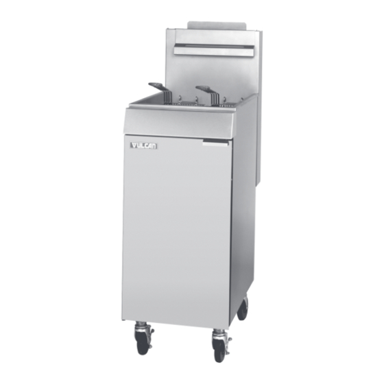
EF SERIES
GAS FRYERS
MODELS
EF3
EF4
EF5
- NOTICE -
P.O. BOX 696, LOUISVILLE, KY 40201-0696
ML-52099
ML-114943
ML-114944
TEL. (502) 778-2791
F-35641 (2-05)
Advertisement
Table of Contents

Related Manuals for Vulcan-Hart EF3 ML-52099


Summary of Contents for Vulcan-Hart EF3 ML-52099
- Page 1 Vulcan Service Technician. Reproduction or other use of this Manual, without the express written consent of Vulcan, is prohibited. For additional information on Vulcan-Hart or to locate an authorized parts and service provider in your area, visit our website at www.vulcanhart.com VULCAN-HART P.O.
-
Page 2: Table Of Contents
EF SERIES GAS FRYERS CONTENTS GENERAL ............................3 INTRODUCTION ........................3 Models ..........................3 INSTALLATION .......................... 3 OIL FILTERING .......................... 3 OPERATION ..........................3 CLEANING ..........................3 LIGHTING PILOT ........................3 SPECIFICATIONS ........................3 Gas Data ..........................3 TOOLS ............................3 Standard .......................... -
Page 3: General
EF SERIES GAS FRYERS GENERAL 4. While still holding knob in light the pilot INTRODUCTION with a taper. Continue to depress knob (approximately 30 seconds) until the pilot remains lit after the knob is released. If Models pilot does not remain lit, repeat steps 2, 3 &... -
Page 4: Removal And Replacement Of Parts
EF SERIES GAS FRYERS REMOVAL AND REPLACEMENT OF PARTS Heat Shield COVERS AND PANELS 1. Remove screws holding heat shield in place (Figure 2). WARNING: SHUT OFF THE GAS BEFORE SERVICING. Door 1. While holding onto the door remove (2) screws securing the door hinge to the fryer bottom front flange (Figure 1). -
Page 5: Burners
EF SERIES GAS FRYERS BURNERS WARNING: SHUT OFF THE GAS BEFORE SERVICING. 1. Remove heat shield as outlined under Cover and Panels. (Optional) 2. Loosen the two mounting bolts at the top of each burner (Figure 3). Figure 4 4. Reverse the procedure to install. THERMOSTAT WARNING: SHUT OFF THE GAS BEFORE SERVICING. - Page 6 EF SERIES GAS FRYERS 5. Remove thermostat mounting screws and 7. Loosen the packing nut and holding nut remove thermostat from mounting bracket (Figure 7). (Figure 5). Figure 7 8. Remove the thermostat bulb from the clamp (Figure 8). Figure 5 6.
-
Page 7: High Limit
EF SERIES GAS FRYERS 10. Reverse the procedure to install. When 6. Loosen the packing nut and the holding installing the new thermostat assembly, nut (Figure 10). do not kink the thermostat capillary. Wrap threads of packing nut with Teflon tape to prevent leakage. -
Page 8: Thermopile
EF SERIES GAS FRYERS 8. Pull the high limit bulb through the underside of the fry tank and remove the high limit. 9. Reverse the procedure to install. When installing the new high limit assembly, do not kink the high limit capillary. Wrap threads of packing nut with Teflon tape to prevent leakage. -
Page 9: Pilot Orifice
EF SERIES GAS FRYERS 3. Remove thermopile from pilot bracket by PILOT loosening the holding nut (Figure 13). WARNING: SHUT OFF THE GAS BEFORE SERVICING. WARNING: ALL GAS JOINTS DISTURBED DURING SERVICING MUST BE CHECKED FOR LEAKS. CHECK WITH SOAP AND WATER SOLUTION (BUBBLES). -
Page 10: Combination Valve
EF SERIES GAS FRYERS 6. Disconnect combination valve union and COMBINATION VALVE pressure fitting (Figure 16). WARNING: SHUT OFF THE GAS BEFORE SERVICING. WARNING: ALL GAS JOINTS DISTURBED DURING SERVICING MUST BE CHECKED FOR LEAKS. CHECK WITH SOAP AND WATER SOLUTION (BUBBLES). DO NOT USE AN OPEN FLAME. -
Page 11: Fry Tank
EF SERIES GAS FRYERS 7. Remove the manifold bracket from the FRY TANK tank assembly by removing the (4) bolts (Figure 18). WARNING: SHUT OFF THE GAS BEFORE SERVICING. WARNING: ALL GAS JOINTS DISTURBED DURING SERVICING MUST BE CHECKED FOR LEAKS. CHECK WITH SOAP AND WATER SOLUTION (BUBBLES). -
Page 12: Service Procedures And Adjustments
EF SERIES GAS FRYERS SERVICE PROCEDURES AND ADJUSTMENTS 7. Turn gas control valve knob to ON. Turn MILLIVOLT CONTROLS TEST thermostat to a setting higher than the shortening temperature. 1. Verify proper gas (natural or propane) is A. If the voltage measures 150 millivolts present. -
Page 13: Pilot Adjustment
EF SERIES GAS FRYERS 5. Allow temperature to stabilize at new setting and compare temperature tester to dial setting. Recalibrate if the temperature does not fall within the range of 330°F to 370°F. 6. If the temperature does not fall within the limits at both settings, replace the thermostat. -
Page 14: Combination Valve Regulator Adjustment
EF SERIES GAS FRYERS 2. Hold the burner nozzle with channel locks 1. Turn the gas control valve knob to OFF and remove the orifice, (Figure 22). Check (Figure 23). the orifice for obstructions or damage. Figure 23 2. Remove the plug from the submanifold and install pressure gauge at this point (Figure 24). - Page 15 EF SERIES GAS FRYERS 6. Read the pressure gauge. The manifold pressure reading should match the pressure rating on the data plate. A. To adjust, remove the cap covering the manifold pressure adjustment screw (Figure 25). Turn the recessed manifold pressure adjustment screw counterclockwise decrease pressure or clockwise to increase...
-
Page 16: Electrical Operation
EF SERIES GAS FRYERS ELECTRICAL OPERATION C. When the thermostat calls for heat CONTROL SYSTEM (closed circuit) power from the DESCRIPTION thermopile is then connected to the other combination valve thermostat 1. The thermopile (PG) provides the total connection through wire 2. control voltage for this system. -
Page 17: System Condition Quick Check Procedures
EF SERIES GAS FRYERS SYSTEM CONDITION QUICK SCHEMATIC CHECK PROCEDURES 1. Use the Pilot Lighting procedure and check millivolts (mV) at wires 3 and 4. A. lf the pilot lights, then pilot combination valve and high limit are good. B. If the pilot will not stay lit, check high limit and open the thermopile circuit. -
Page 18: Troubleshooting
EF SERIES GAS FRYERS TROUBLESHOOTING SYMPTOM CAUSE REMEDY The temperature of the Insufficient gas supply to Adjust gas supply at gas combination shortening drops, or unit. valve. excessive recovery time is required. Ventilation system pulling Relocate fryer. heat out of heat exchanger and flue box. - Page 19 EF SERIES GAS FRYERS SYMPTOM CAUSE REMEDY Leaking tank. Foam-over by depleted Replace shortening. shortening permits oil to drip from the tank surface, giving appearance of leaking. Careless draining Gas control valve knob should be in procedures. PILOT or OFF position before draining oil.
- Page 20 F35641 (02-05) PRINTED IN U.S.A.