Table of Contents
Advertisement
Advertisement
Table of Contents

Related Manuals for Powerware Powerware 5119


Summary of Contents for Powerware Powerware 5119
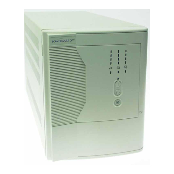
- Page 1 02/15/01 ® Powerware 5119 User’s Guide 1000-3000 VA www.powerware.com...
- Page 2 Powerware is a registered trademark and Advanced Battery Management (ABM) is a trademark of Powerware Corporation. Copyright 1999 Powerware Corporation, Raleigh, NC. All rights reserved. No part of this document may be reproduced in any way without the express written approval of Powerware Corporation.
- Page 3 For Users in the United States Only NOTE This equipment has been tested and found to comply with the limits for a Class A digital device pursuant to Part 15 of FCC Rules. These limits are designed to provide reasonable protection against harmful interference when this equipment is operated in a commercial environment.
-
Page 4: Special Symbols
Special Symbols The following are examples of symbols used on the UPS to alert you to important information: RISK OF ELECTRIC SHOCK associated warning should be observed. CAUTION: REFER TO OPERATOR’S MANUAL additional information, such as important operating and maintenance instructions. -
Page 5: Table Of Contents
ABLE OF 1 Powerware 5119 – One of the Best! 2 Installation ........... . . - Page 6 ..........Powerware 5119 User’s Guide...
-
Page 7: Powerware 5119 - One Of The Best
— causing hours of lost productivity and expensive repairs. With the Powerware 5119, you can safely eliminate the effects of power disturbances and guard the integrity of your equipment. The Powerware 5119’s flexibility to handle an array of network devices makes it the... - Page 8 Start-on-battery compatibility allows you to power up the UPS even if utility power is not available. Optional power communication cards provide enhanced communication capabilities for increased power protection and longer battery backup times. The Powerware 5119 is backed by worldwide agency approvals. Powerware 5119 User’s Guide www.powerware.com ®...
-
Page 9: Installation
SAVE THESE INSTRUCTIONS. This manual contains important instructions that you should follow during installation and maintenance of the UPS and batteries. Please read all instructions before operating the equipment and save this manual for future reference. Powerware 5119 User’s Guide www.powerware.com ®... -
Page 10: Installing The Ups
UPS. W A R N I N G • • C (104 F). Do not operate near water C A U T I O N Powerware 5119 User’s Guide ® www.powerware.com... - Page 11 “Operation” on page 11. To change the factory-set defaults, see “Configuration” on page 15. NOTE The UPS charges to 90% in approximately 4 hours. However, it is recommended that the UPS charge for 24 hours after installation or long storage. Powerware 5119 User’s Guide www.powerware.com ®...
- Page 12 Installation Connect communication cable from computer to UPS (optional) Connect battery to UPS (if applicable) Battery Cabinet & Powerware ® Connect equipment to UPS 5119 User’s Guide www.powerware.com...
-
Page 13: Ups Rear Panels
Installation UPS Rear Panels This section shows the rear panels of all Powerware 5119 models. Powerware 5119 User’s Guide www.powerware.com ®... - Page 14 Installation Powerware 5119 User’s Guide www.powerware.com ®...
- Page 15 Figure 8. 2000-2400 VA, 230V Rear Panel Communication Port Battery Connector Output Circuit Breakers Load Segment 1 (Three IEC-320 Receptacles) Load Segment 2 (Three IEC-320 Receptacles) (Three IEC-320 Receptacles) Powerware 5119 User’s Guide www.powerware.com ® Load Segment 3 Network Transient Protector Load Segment 3 Network Transient Protector Figure 9.
- Page 16 Installation Powerware 5119 User’s Guide www.powerware.com ®...
-
Page 17: Operation
To turn on the UPS without using utility power, press and hold the On button for three seconds. When the UPS starts on battery, it does not conduct a self-test to conserve battery power. Turning the UPS Off To turn off the UPS, press the Off Powerware 5119 User’s Guide www.powerware.com ®... -
Page 18: Ups Front Panel
Figure 10 shows the UPS front panel indicators and controls. AC Input LEDs Site Wiring Fault Indicator Test/Alarm Reset Button Battery Charge LEDs Communication Indicator On Button Off Button Powerware ® Load Level LEDs 5119 User’s Guide www.powerware.com... -
Page 19: Ac Input Leds
The third LED indicates that the UPS is using the Double Boost feature to automatically correct voltage fluctuations. If any AC Input LEDs are red, see page 34 for more information. Battery Charge LEDs Powerware 5119 User’s Guide www.powerware.com ®... -
Page 20: Load Level Leds
For more information, see “Troubleshooting” on page 33. NOTE All three Battery Charge LEDs should be lit and the UPS must not be in Battery mode to perform the self-test. 66-100% 33-66% 5-33% button for three seconds to initiate the self-test. Powerware ® 5119 User’s Guide www.powerware.com... -
Page 21: Configuration
When the UPS is in Configuration mode, the LEDs represent the configuration options. The control buttons (On button and are used to modify the UPS configuration. Figure 14 shows the LEDs and Table 1 explains the corresponding options. Powerware 5119 User’s Guide www.powerware.com ®... - Page 22 ONCE to toggle the selected option on or LEDs Press the On and Test/Alarm Reset buttons simultaneously to toggle between Configuration and Operation mode. Powerware button button simultaneously to & 5119 User’s Guide www.powerware.com...
- Page 23 Site Wiring Fault ON (default) Alarm OFF* Low Battery Alarm ON (default) Powerware 5119 User’s Guide www.powerware.com ® Explanation Nominal input voltage on low voltage models is 120V and on high voltage models is 230V; all other nominal input voltages are disabled.
- Page 24 The UPS accepts an input voltage within -20% to +20% of 100V or 208V nominal input voltage before switching to battery. All factory-set defaults are active. One or more factory-set defaults have been changed. Powerware ® 5119 User’s Guide www.powerware.com...
-
Page 25: Ups Maintenance
When the Battery Service indicator illuminates, the batteries may need replacing (see Figure 10 on page 12). Conduct a self-test by pressing the button. If the indicator stays on, contact your service representative to order new batteries. Powerware 5119 User’s Guide www.powerware.com ®... -
Page 26: Replacing Batteries
NOTE When the UPS is online, all three Battery Charge LEDs should be lit before hot-swapping the batteries. DO NOT DISCONNECT the batteries while the UPS is in Battery mode. W A R N I N G C A U T I O N Powerware 5119 User’s Guide ® www.powerware.com... -
Page 27: How To Replace External Batteries
2. Plug the new battery cabinet into the UPS as shown in Figure 15. Battery Connector Figure 15. External Battery Connections (120V Model Shown) Powerware 5119 User’s Guide www.powerware.com ® Battery Cabinet Plug the battery cable into the battery... -
Page 28: How To Replace Internal Batteries
UPS Maintenance How to Replace Internal Batteries Use the following steps to replace internal batteries: 1. Pull the front panel forward and snap into place as shown. Powerware 5119 User’s Guide www.powerware.com ®... -
Page 29: Testing New Batteries
Battery Charge LEDs should show a charge. If the Battery Service indicator stays on, check the battery connections. See the troubleshooting guide on page 33 or call your service representative if the problem persists. Powerware 5119 User’s Guide www.powerware.com ®... -
Page 30: Recycling The Used Battery
For more information, contact your local recycling or hazardous waste center. W A R N I N G C A U T I O N Powerware 5119 User’s Guide ® www.powerware.com... -
Page 31: Additional Ups Features
When the UPS receives a command from the computer to establish communication, the Communication indicator on the UPS front panel illuminates (see Figure 10 on page 12). When data is transferring, the Communication indicator flashes. Powerware 5119 User’s Guide www.powerware.com ®... -
Page 32: Pin Out
Plug-and-play software enable trigger (activates when pin changes from +12V to -12V) Remote Emergency Power-Off: UPS total output can be kept off with low signal or closing relay contact Auxiliary Control Power Connection to chassis Powerware 5119 User’s Guide www.powerware.com ®... -
Page 33: Network Transient Protector
Option modules help your UPS communicate in a variety of networking environments and are installed in the UPS option slot. See the manual that accompanies each module for more information, or contact your sales representative. Powerware 5119 User’s Guide www.powerware.com ®... - Page 34 Additional UPS Features Powerware 5119 User’s Guide www.powerware.com ®...
-
Page 35: Specifications
C H A P T E R 7 PECIFICATIONS This section provides the following specifications for the Powerware 5119 models: Electrical input and output Weights and dimensions Environmental and safety Indicators and controls Battery Table 3. Model List UPS Models Table 4. - Page 36 2400 VA: 36 lb (16 kg) 3000 VA: 41 lb (19 kg) 7 x 8.8 x 17.1 inches (17.8 x 22.3 x 43.4 cm) Powerware 230V Models PW5119 1000i: 1000 VA, 670W PW5119 1500i: 1500 VA, 960W PW5119 2000i: 2000 VA, 1400W...
- Page 37 Charging Advanced charging for faster recovery; approximately 4 hours to 90% usable capacity at nominal line and no supplementary power supply load Monitoring Advanced monitoring for earlier failure detection and warning Powerware 5119 User’s Guide www.powerware.com ® 120V Models 0°C to 40°C (32°F to 104°F); UL tested 25°C (77°F) -20°C to 60°C (-4°F to 140°F)
- Page 38 Table 10. Battery Run Times (in Minutes) Load (VA) 1000 Model 1000 1500 2000 2400 3000 NOTE Battery times are approximate and vary depending on the load configuration and battery charge. 1500 Model 2000 Model Powerware ® 2400 Model 3000 Model 5119 User’s Guide www.powerware.com...
-
Page 39: Troubleshooting
The UPS switches Input voltage in your area differs frequently between battery from the UPS nominal. and AC input. Powerware 5119 User’s Guide www.powerware.com ® button. If UPS Action Push the circuit breaker button or replace the fuse (see “UPS Rear Panels”... - Page 40 To disable this alarm, see “Configuration Mode” on page 15. 3 to 5 minutes or less of battery power remains (depending on load and battery charge). Prepare for a shutdown. Save your work and turn off your equipment. Powerware 5119 User’s Guide ® www.powerware.com...
-
Page 41: Service And Support
Serial number Version number (if available) Date of failure or problem Symptoms of failure or problem Customer return address and contact information Powerware 5119 User’s Guide www.powerware.com ® Action Plug the UPS into a wall outlet for 24 hours to charge the battery. - Page 42 A replacement or repair unit will be shipped, freight prepaid for all warrantied units. NOTE For critical applications, immediate replacement may be available. Call the for the dealer or distributor nearest you. Powerware 5119 User’s Guide www.powerware.com ®...