Table of Contents
Advertisement
Quick Links
Advertisement
Table of Contents

Related Manuals for Powerware UPS 1000 - 2200


Summary of Contents for Powerware UPS 1000 - 2200
- Page 1 UPS 1000 - 2200 VA User’s Manual...
-
Page 3: Table Of Contents
Powerware 5125 User’s Manual 1000–2200 VA 1019297 Revision A Table of contents 1. Introduction ... 7 2. Installation ... 8 Inspecting the Equipment ... 8 Installing the UPS ... 8 UPS Rear Panels ... 9 3. Operation and Configuration ... 10 Operating Models ... - Page 4 Copyright 2002 The contents of this manual are the copyright of the publisher and may not be reproduced (even extracts) unless permission granted. Every care has been taken to ensure the accuracy of the information contained in this manual, but no liability can be accepted for any errors or omission.
- Page 5 92/31/EEC, Amending Directive 89/336/EEC relating to EMC The EC Declaration of Conformity is available upon request for products with a CE mark. For copies of the EC Declaration of Conformity, contact: Powerware Oy Koskelontie 13 FIN-02920 Espoo, Finland Phone: +358-9-452 661...
-
Page 6: Special Symbols
Special Symbols The following are examples of symbols used on the UPS to alert you to important information: RISK OF ELECTRIC SHOCK - Indicates that a risk of electric shock is present and the associated warning should be observed. CAUTION: REFER TO OPERATOR’S MANUAL - Refer to your operator’ s manual for additional information, such as important operating and maintenance instructions. -
Page 7: Introduction
— causing hours of lost productivity and expensive repairs. With the Powerware 5125, you can safely eliminate the effects of power disturbances and guard the integrity of your equipment. The Powerware 5125 was designed for critical applications such as PCs, severs, workstations, and telecommunications equipment. -
Page 8: Installation
2 Installation Inspecting the Equipment If any equipment has been damaged during shipment, keep the shipping cartons and packing materials for the carrier or place of purchase and file a claim for shipping damage. If you discover damage after acceptance, file a claim for concealed damage. To file a claim for shipping damage or concealed damage: 1) File with the carrier within 15 days of receipt of the equipment;... -
Page 9: Ups Rear Panels
NOTE. If more than two EBMs are installed, an external battery charger is recommended for faster recharge times. Figure 2. Installation UPS Rear Panels This section shows the rear panels of the Powerware 5125 models. Figure 3. PW5125 1000i and PW5125 1500i Rear Panel 1019297 1000 - 2200 VA Revision A User’s Manual... -
Page 10: Operation And Configuration
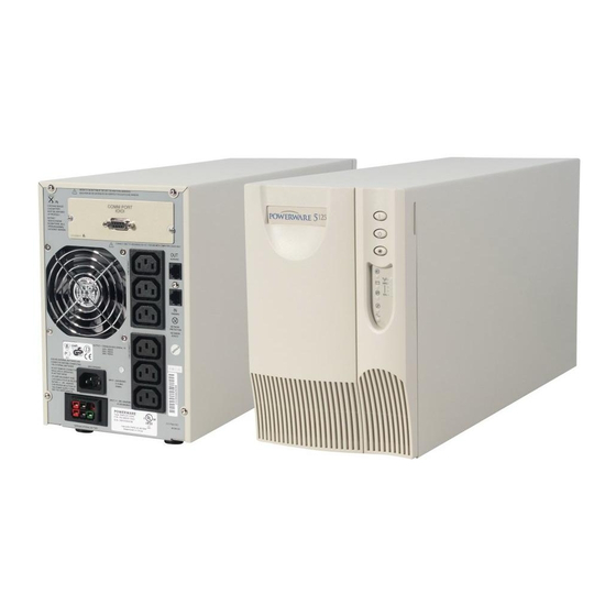
Figure 4. PW5125 2200i Rear Panel 3 Operation and Configuration Operating Modes Powerware 5125’ s front panel indicates the UPS status through the UPS indicators. Figure 5 shows the UPS front panel indicators and controls. Figure 5. UPS Front Panel... -
Page 11: Stanby Mode
Standby Mode When the UPS is turned off and remains plugged into a power outlet, the UPS is in Standby mode. The indicator flashes and the bar graph indicators are off, indicating that power is not available from the UPS output receptacles. The battery recharges when necessary. Normal Mode During Normal mode, the indicator illuminates and the front panel displays the... -
Page 12: Battery Mode
UPS Configuration Your PW5125 UPS can be configured by using a configuration software that can be find on web (www.emea.powerware.com/product/PW5125.htm). This software is a DOS based program that can be executed from either a DOS box, from a Windows shortcut, or from the Windows Start, Run dialog box. -
Page 13: Turning The Ups Off
UPS alarm indicator stays on, see Table 2 on page 22. Communication Port The Powerware 5125 is factory-installed with a Single-Port Module. To establish communication between the UPS and a computer, connect your computer to the UPS communication port using the supplied communication cable. -
Page 14: Network Transient Protector
Network Transient Protector The Network Transient Protector, shown in Figure 9, is located on the rear panel and has jacks labeled IN and OUT. This feature accommodates a single RJ–45 (10BaseT) network connector. Connect the input connector of the equipment you are protecting to the jack labeled IN. Connect the output connector to the jack labeled OUT. -
Page 15: Load Segments
Load Segments Load segments are sets of receptacles that can be controlled by power management software, providing an orderly shutdown and startup of your equipment. For example, during a power outage, you can keep key pieces of equipment running while you turn off other equipment. -
Page 16: Ups Maintenance
4 UPS Maintenance UPS and Battery Care For the best preventive maintenance, keep the area around the UPS clean and dust–free. If the atmosphere is very dusty, clean the outside of the system with a vacuum cleaner. For full battery life, keep the UPS at an ambient temperature of 25°C . Storing the UPS and Batteries If you store the UPS for a long period, recharge the battery every 6 months by plugging the UPS into a power outlet. - Page 17 How to Replace Extended Battery Modules Use the following procedure to replace EBMs: Unplug the EBM cable from the UPS. Replace the EBM. See “Recycling the Used Battery” on page 20 for proper disposal. Plug the new EBM into the UPS as shown in Figure 12. For additional EBMs, plug the EBM cable of the second cabinet into the battery connector on the first EBM.
- Page 18 Use the following procedure to replace internal batteries: Remove the UPS front panel by pulling the top. Slide up and remove the metal battery cover. 1000 VA units. Disconnect the red battery cable on the front of the battery. Pull the battery out onto a flat, stable surface.
-
Page 19: Testing New Batteries
1500 and 2200 VA units. Pull the battery out onto a flat, stable surface. Press on the black tab on the battery cable connector to disconnect the battery. See “Recycling the Used Battery” on page 20 for proper disposal. Install the new batteries in the reverse order of removal. Reinstall the metal battery cover removed in Step 2. -
Page 20: Recycling The Used Battery
Recycling the Used Battery Contact your local recycling or hazardous waste center for information on proper disposal of the used battery. WARNING Do not dispose of the battery or batteries in a fire. Batteries may explode. Proper disposal of batteries is required. Refer to your local codes for disposal requirements. Do not open or mutilate the battery or batteries. -
Page 21: Silencing An Audible Alarm
Silencing an Audible Alarm To silence the alarm for an existing fault, press the alarm beeps, overriding the previous alarm silencing. The alarm does not silence if there is a low battery condition. . t r a l f l i a Table 2. - Page 22 c i f 100% i l i a t l y l l . y l . s t t s i l l a . t e 1 – 1 – 1000 - 2000 VA User’s Manual . e l l i t a t l e f f...
-
Page 23: Specifications
6 Specifications Table 3. Model Specifications Table 4. Weights and Dimensions Table 5. Power Connections i t a e t l t a l t a l a t l Table 6. Technical Specifications 1019297 Revision A x D x ) –... - Page 24 i t a t i s i t a i t a i t l t i s i t l Table 7. Environmental and Safety Table 8. Battery Table 9. Battery Run Times (in Minutes at Full/Half Load) C ° C °...