Powerware 5125 User Manual
Two-in-one 2400-3000 va
Hide thumbs
Also See for 5125:
- User manual (24 pages) ,
- User manual (52 pages) ,
- Quick start manual (25 pages)
Table of Contents
Advertisement
Advertisement
Table of Contents

Related Manuals for Powerware 5125


Summary of Contents for Powerware 5125
-
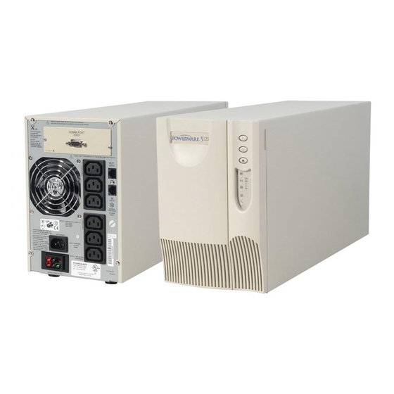
Page 1: Powerware 5125
® Powerware 5125 Two-in-One User’s Guide 2400–3000 VA www.powerware.com... - Page 2 Powerware is a registered trademark and Advanced Battery Management Plus (ABM Plus), X-Slot, and ConnectUPS are trademarks of Powerware Corporation. Copyright 2002 Powerware Corporation, Raleigh, NC, USA. All rights reserved. No part of this document may be reproduced in any way without the express written approval of Powerware Corporation.
- Page 3 Class A EMC Statements FCC Part 15 NOTE This equipment has been tested and found to comply with the limits for a Class A digital device, pursuant to part 15 of the FCC Rules. These limits are designed to provide reasonable protection against harmful interference when the equipment is operated in a commercial environment.
-
Page 4: Special Symbols
Special Symbols The following are examples of symbols used on the UPS to alert you to important information: RISK OF ELECTRIC SHOCK - Indicates that a risk of electric shock is present and the associated warning should be observed. CAUTION: REFER TO OPERATOR’S MANUAL - Refer to your operator’s manual for additional information, such as important operating and maintenance instructions. -
Page 5: Table Of Contents
............Powerware 5125 Two-in-One (2400–3000 VA) User’s Guide www.powerware.com... - Page 6 ............Powerware 5125 Two-in-One (2400–3000 VA) User’s Guide www.powerware.com...
-
Page 7: Powerware 5125
— causing hours of lost productivity and expensive repairs. With the Powerware 5125, you can safely eliminate the effects of power disturbances and guard the integrity of your equipment. The Powerware 5125 is designed for critical applications such as PCs, severs, workstations, and telecommunications equipment. - Page 8 Emergency shutdown control through the Remote Emergency Power-Off (REPO) port. Optional X-Slot modules provide enhanced communication capabilities for increased power protection and control. The Powerware 5125 is backed by worldwide agency approvals. Powerware 5125 Two-in-One (2400–3000 VA) User’s Guide www.powerware.com ®...
-
Page 9: Safety Warnings
(95% max). To comply with international standards and wiring regulations, the total equipment connected to the output of this UPS must not have an earth leakage current greater than 2.5 milliamperes. Powerware 5125 Two-in-One (2400–3000 VA) User’s Guide www.powerware.com ®... - Page 10 (maksimalt 95%). I overensstemmelse med internationale normer og bestemmelser for el-installation må det udstyr, der er forbundet til udgangen af denne UPS, tilsammen ikke overskride en jordafdelingsspænding på mere end 2,5 milliampere. Powerware 5125 Two-in-One (2400–3000 VA) User’s Guide www.powerware.com ®...
-
Page 11: Belangrijke Veiligheidsinstructies
(max. 95%). Om aan de internationale normen en bedradingsvoorschriften te voldoen mag de gehele apparatuur die op de uitgang van deze UPS is aangesloten, geen aardlekstroom van meer dan 2,5 milliampère hebben. Powerware 5125 Two-in-One (2400–3000 VA) User’s Guide www.powerware.com ®... - Page 12 Ympäristön lämpötila ei saa ylittää 40 •C. Älä käytä lähellä vettä ja vältä kosteita tiloja (95 % maksimi). Kansainväliset normit ja johdotusmääräykset vaativat, että kaikkien tämän UPS-laitteen ulostulokytkentöjen yhteinen maavuotovirta ei ylitä 2,5 milliampeeria (mA). Powerware 5125 Two-in-One (2400–3000 VA) User’s Guide www.powerware.com ®...
- Page 13 Afin d’être conforme aux normes et règlements internationaux de câblage, le courant de fuite à la terre de la totalité du matériel branché sur la sortie de l’onduleur ne doit pas dépasser 2,5 mA. Powerware 5125 Two-in-One (2400–3000 VA) User’s Guide www.powerware.com ®...
- Page 14 übersteigen. Die USV nicht in der Nähe von Wasser oder in extrem hoher Luftfeuchtigkeit (max. 95 %) betreiben. Um internationale Normen und Verdrahtungsvorschriften zu erfüllen, dürfen die an den Ausgang dieser USV angeschlossenen Geräte zusammen einen Erdschlußstrom von insgesamt 2,5 Milliampere nicht überschreiten. Powerware 5125 Two-in-One (2400–3000 VA) User’s Guide www.powerware.com ®...
- Page 15 Die Batterien müssen ordnungsgemäß entsorgt werden. Hierbei sind die örtlichen Bestimmungen zu beachten. Batterien niemals verbrennen, da sie explodieren können. ÐñïåéäïðïéÞóåéò ÁóöÜëåéáò ÓÇÌÁÍÔÉÊÅÓ ÏÄÇÃÉÅÓ ÁÓÖÁËÅÉÁÓ ÖÕËÁÎÔÅ ÁÕÔÅÓ ÔÉÓ ÏÄÇÃÉÅÓ ÔÏ ÐÁÑÏÍ ÅÃ×ÅÉÑÉÄÉÏ ÐÅÑÉÅ×ÅÉ ÓÇÌÁÍÔÉÊÅÓ ÏÄÇÃÉÅÓ ÁÓÖÁËÅÉÁÓ ÊÉÍÄÕÍÏÓ ÐÑÏÅÉÄÏÐÏÉÇÓÇÊ • Powerware 5125 Two-in-One (2400–3000 VA) User’s Guide www.powerware.com ®...
-
Page 16: Avvisi Di Sicurezza
Non rimuovere nè scollegare il cavo di ingresso quando il gruppo statico di continuità è acceso poichè in tal modo si disattiverebbe il collegamento a terra di sicurezza del gruppo statico di continuità e dell’apparecchiatura ad esso collegata. Powerware 5125 Two-in-One (2400–3000 VA) User’s Guide www.powerware.com ®... -
Page 17: Viktig Sikkerhetsinformasion
Romtemperaturen må ikke overskride 40•C. Den må ikke brukes i nærheten av vann eller ved meget høy luftfuktighet (95% maks.). Powerware 5125 Two-in-One (2400–3000 VA) User’s Guide www.powerware.com ®... - Page 18 Para estar de acordo com os padrões internacionais e os regulamentos de fiação, o equipamento total conectado à saída desta UPS não deve ter uma corrente de fuga à terra maior que 2,5 miliampères. Powerware 5125 Two-in-One (2400–3000 VA) User’s Guide www.powerware.com ®...
- Page 19 током устанавливайте ИБП в закрытом помещении с контролируемыми температурой и влажностью, в котором отсутствуют проводящие загрязняющие вещества. Температура окружающего воздуха не должна превышать 40•С. Не эксплуатируйте устройство около воды или в местах с повышенной влажностью (макс. 95%). Powerware 5125 Two-in-One (2400–3000 VA) User’s Guide www.powerware.com ®...
-
Page 20: Advertencias De Seguridad
No retire o desenchufe el cable de entrada mientras el SIE se encuentre encendido. Esto suprime la descarga a tierra de seguridad del SIE y de los equipos conectados al SIE. Powerware 5125 Two-in-One (2400–3000 VA) User’s Guide www.powerware.com ®... - Page 21 Denna UPS-enhet har en egen energikälla (batterier). De utgående kontakterna kan vara strömförande när UPS-enheten inte är ansluten till en växelströmkälla. Ta aldrig bort nätsladden när UPS-enheten är påslagen. Detta tar bort skyddsjordningen från både UPS-enheten och den anslutna utrustningen. Powerware 5125 Two-in-One (2400–3000 VA) User’s Guide www.powerware.com ®...
- Page 22 V I K T I G T Batterierna kan ge elektriska stötar eller brännskador från hög kortslutningsström. Följ tillämpliga anvisningar. Batterierna måste avyttras enligt anvisningarna i lokal lagstiftning. Använda batterier får aldrig brännas upp. De kan explodera. Powerware 5125 Two-in-One (2400–3000 VA) User’s Guide www.powerware.com ®...
-
Page 23: Installation
15 days to your service representative. UPS Setup The Powerware 5125 UPS is designed for flexible configurations and can be installed in a rack or as a standalone cabinet. If you are installing the UPS in a rack, continue to the following section, “Rack-Mount Setup;”... -
Page 24: Rack-Mount Setup
2. Attach the supplied mounting handles to the mounting brackets (see Figure 2). 3. If installing optional EBMs, repeat Steps 1 and 2 for each cabinet. Mounting Handle Mounting Bracket Figure 2. Installing the Mounting Handles Powerware 5125 Two-in-One (2400–3000 VA) User’s Guide www.powerware.com ®... -
Page 25: Cabinet Setup
The rack-mounting brackets must be removed before positioning the cabinets for the cabinet setup. Unscrew and remove the mounting brackets on each side of all cabinets as shown in Figure 4. Mounting Bracket Figure 4. Removing the Mounting Brackets Powerware 5125 Two-in-One (2400–3000 VA) User’s Guide www.powerware.com ®... - Page 26 3. Position the pedestals over the end of the UPS cabinet so that the weight of the unit is evenly distributed. Secure the pedestals with the screws provided in the accessory kit. Figure 6. Installing Pedestals on a Single Cabinet Powerware 5125 Two-in-One (2400–3000 VA) User’s Guide www.powerware.com ®...
- Page 27 7. Position two of the pedestals over the edge of each cabinet so that the weight of the unit is evenly distributed. Secure the pedestals with the screws provided in the accessory kit. Powerware 5125 Two-in-One (2400–3000 VA) User’s Guide www.powerware.com ®...
- Page 28 Figure 10. Pedestals with Two Cabinets NOTE Pedestals are required for one and two cabinet installations. EBM brackets are required for all vertical EBM installations. Air Vents Figure 11. Vertical Cabinet Setup Powerware 5125 Two-in-One (2400–3000 VA) User’s Guide www.powerware.com ®...
- Page 29 EBM Bracket Figure 12. Installing the EBM Brackets (Top View with Pedestals) 10. If installing additional EBMs, repeat Step 9 for each cabinet. Continue to the following section, “Installing the UPS.” Powerware 5125 Two-in-One (2400–3000 VA) User’s Guide www.powerware.com ®...
-
Page 30: Installing The Ups
EBM. Up to four EBMs may be connected to the UPS. Ground Bonding Screw Power Cord Output Receptacles Communication Port Circuit Breakers X-Slot UPS Battery Connector EBM Battery Cable Connectors Figure 13. Typical Installation with Two EBMs Powerware 5125 Two-in-One (2400–3000 VA) User’s Guide www.powerware.com ®... - Page 31 24 hours after installation or long-term storage. NOTE If more than two EBMs are installed, an external battery charger is recommended for faster recharge times. Powerware 5125 Two-in-One (2400–3000 VA) User’s Guide www.powerware.com ®...
-
Page 32: Ups Rear Panels
Installation UPS Rear Panels This section shows the rear panels of the Powerware 5125 models. Communication Port 5-15 Receptacles Circuit Breakers X-Slot L5-30 Receptacle Power Cord REPO Port with L5-30P Battery Connector Figure 14. 2400–3000 VA, 100/120V Rear Panel Communication Port... - Page 33 Installation 16A, IEC 320-C20 Communication Port IEC 320-C13 Receptacles Input Connector X-Slot Circuit Breakers REPO Port IEC 320-C19 Receptacle Battery Connector Figure 17. 3000 VA, 200–240V (PW5125 3000g RM) Rear Panel Powerware 5125 Two-in-One (2400–3000 VA) User’s Guide www.powerware.com ®...
- Page 34 Installation Powerware 5125 Two-in-One (2400–3000 VA) User’s Guide www.powerware.com ®...
-
Page 35: Operation
To turn off the UPS, press and hold the Off button until the long beep ceases (approximately five seconds). The indicator begins to flash and the UPS remains in Standby mode until you unplug the UPS from the power outlet. Powerware 5125 Two-in-One (2400–3000 VA) User’s Guide www.powerware.com ®... -
Page 36: Initiating The Self-Test
UPS are checked. If the alarm beeps or a UPS alarm indicator stays on, see Table 8 on page 52. Operating Modes Powerware 5125’s front panel indicates the UPS status through the UPS indicators. Figure 18 shows the UPS front panel indicators and controls. Indicator Legend... -
Page 37: Normal Mode
Immediately complete and save your work to prevent data loss and similar difficulties. When utility power is restored after the UPS shuts down, the UPS automatically restarts. Powerware 5125 Two-in-One (2400–3000 VA) User’s Guide www.powerware.com ®... -
Page 38: Bypass Mode
UPS is in Standby mode. The indicator flashes and the load level indicators are off, indicating that power is not available from the UPS output receptacles. The battery recharges when necessary. Powerware 5125 Two-in-One (2400–3000 VA) User’s Guide www.powerware.com ®... -
Page 39: Additional Ups Features
X-Slot modules allow the UPS to communicate in a variety of networking environments and with different types of devices. The Powerware 5125 is factory-installed with a Single-Port module and is compatible with any X-Slot module, including: Multi-Server Module - has six serial communication ports that can communicate with UPSs, terminals, computers, and modems. -
Page 40: Single-Port Module
Additional UPS Features Single-Port Module The Powerware 5125 is factory-installed with a Single-Port Module. To establish communication between the UPS and a computer, connect your computer to the UPS communication port using the supplied communication cable. When the communication cable is installed, power management software can exchange data with the UPS. - Page 41 2. Move the J3 jumper to the AS/400 position to enable the On-Bypass relay as shown in Figure 23. On-Bypass On-Bypass Disabled Enabled NORM AS/400 On-Bypass Relay Jumper (J3) Figure 23. On-Bypass Relay Jumper Powerware 5125 Two-in-One (2400–3000 VA) User’s Guide www.powerware.com ®...
-
Page 42: Load Segments
Load Segment 3 Load Segment 2 Figure 24. UPS Load Segments (120V Model Shown) Load Segment 2 Load Segment 1 Load Segment 3 Figure 25. UPS Load Segments (PW5125 3000g RM Model Shown) Powerware 5125 Two-in-One (2400–3000 VA) User’s Guide www.powerware.com ®... -
Page 43: Remote Emergency Power-Off
Additional UPS Features Remote Emergency Power-Off The Powerware 5125 includes a REPO port that allows power to be switched off at the UPS output receptacles from a customer-supplied switch in a remote location. The REPO feature shuts down the protected equipment immediately and does not follow the orderly shutdown procedure initiated by any power management software. - Page 44 6. Plug in the UPS and start the UPS by pressing the On button. 7. Activate the external REPO switch to test the REPO function. 8. De-activate the external REPO switch and restart the UPS. Powerware 5125 Two-in-One (2400–3000 VA) User’s Guide www.powerware.com ®...
-
Page 45: Ups Maintenance
24 hours after long-term storage. Check the battery recharge date on the shipping carton label. If the date has expired and the batteries were never recharged, do not use the UPS. Contact your service representative. Powerware 5125 Two-in-One (2400–3000 VA) User’s Guide www.powerware.com ®... -
Page 46: Replacing The Electronics Module
5. Replace the electronics module and secure to the UPS chassis with the screws removed in Step 3. 6. Replace the front panel. 7. Reconnect any cables removed in Step 1. Powerware 5125 Two-in-One (2400–3000 VA) User’s Guide www.powerware.com ®... -
Page 47: When To Replace Batteries
2) Use tools with insulated handles; 3) Do not lay tools or metal parts on top of batteries. ELECTRIC ENERGY HAZARD. Do not attempt to alter any battery wiring or connectors. Attempting to alter wiring can cause injury. Powerware 5125 Two-in-One (2400–3000 VA) User’s Guide www.powerware.com ®... -
Page 48: How To Replace Extended Battery Modules
6. For additional EBMs, plug the EBM cable into the battery connector of each EBM. EBM Brackets UPS Battery Connector EBM Battery Connectors EBM Cables Figure 27. EBM Connections (120V Model Shown) Powerware 5125 Two-in-One (2400–3000 VA) User’s Guide www.powerware.com ®... -
Page 49: How To Replace Internal Batteries
UPS. Use the following procedure to replace internal batteries: 1. Remove the UPS front panel by pulling on both ends. 2. Unscrew and set aside the battery retaining bracket. Powerware 5125 Two-in-One (2400–3000 VA) User’s Guide www.powerware.com ®... -
Page 50: Testing New Batteries
After the test is finished, the indicator should turn off. If the indicator stays on, check the battery connections. Call your service representative if the problem persists. Powerware 5125 Two-in-One (2400–3000 VA) User’s Guide www.powerware.com ®... -
Page 51: Recycling The Used Battery
Do not discard the UPS or the UPS batteries in the trash. This product contains sealed, lead-acid batteries and must be disposed of properly. For more information, contact your local recycling or hazardous waste center. Powerware 5125 Two-in-One (2400–3000 VA) User’s Guide www.powerware.com ®... - Page 52 UPS Maintenance Powerware 5125 Two-in-One (2400–3000 VA) User’s Guide www.powerware.com ®...
-
Page 53: Specifications
C H A P T E R 7 PECIFICATIONS This section provides the following specifications for the Powerware 5125 models: : Electrical input and output : Weights and dimensions : Environmental and safety : Battery Table 2. Model Specifications Power Levels... - Page 54 UL 1778, CAN/CSA C22.2, No. 107.1; EN 50091-1-1 and IEC 60950 Agency Markings UL, cUL UL and cUL; CE, TÜV-GS (model dependent) FCC Part 15, ICES-003, VCCI EN 50091-2, FCC Part 15, ICES-003 Powerware 5125 Two-in-One (2400–3000 VA) User’s Guide www.powerware.com ®...
- Page 55 4 EBMs 2400 VA 7/19 35/73 60/124 85/177 110/229 3000 VA 5/15 25/61 49/103 69/146 90/190 NOTE Battery times are approximate and vary depending on the load configuration and battery charge. Powerware 5125 Two-in-One (2400–3000 VA) User’s Guide www.powerware.com ®...
- Page 56 Specifications Powerware 5125 Two-in-One (2400–3000 VA) User’s Guide www.powerware.com ®...
-
Page 57: Troubleshooting
To silence the alarm for an existing fault, press the button. If UPS status changes, the alarm beeps, overriding the previous alarm silencing. The alarm does not silence if there is a low battery condition. Powerware 5125 Two-in-One (2400–3000 VA) User’s Guide www.powerware.com ®... - Page 58 3 minutes or less of battery power remains (depending on load configuration and battery charge). Save your work and turn off your equipment. The alarm cannot be silenced. 1 beep every 5 seconds. Powerware 5125 Two-in-One (2400–3000 VA) User’s Guide www.powerware.com ®...
- Page 59 UPS. UPS fault condition. Save your work and turn off your equipment. Turn off and unplug the UPS. Contact your service representative. The alarm cannot be silenced. Powerware 5125 Two-in-One (2400–3000 VA) User’s Guide www.powerware.com ®...
-
Page 60: Service And Support
A replacement or repair unit will be shipped, freight prepaid for all warrantied units. NOTE For critical applications, immediate replacement may be available. Call the Help Desk for the dealer or distributor nearest you. Powerware 5125 Two-in-One (2400–3000 VA) User’s Guide www.powerware.com ®...