Table of Contents
Advertisement
Quick Links
Advertisement
Table of Contents

Related Manuals for Delta 36-725 T2


Summary of Contents for Delta 36-725 T2
- Page 1 10-inch Contractor Table Saw www.DeltaMachinery.com Instruction Manual 36-725 T2 To reduce risk of serious injury, thoroughly read and comply with all warnings and instructions in this manual and on product. KEEP THIS MANUAL NEAR YOUR SAW FOR EASY REFERENCE AND TO INSTRUCT OTHERS.
-
Page 2: Table Of Contents
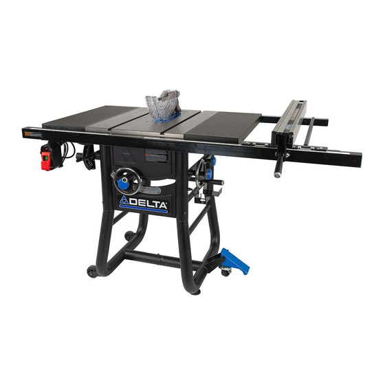
TILTING THE BLADE............26 PARTS, SERVICES AND WARRANTY ASSISTANCE... 44 FEATURES SPECIFICATIONS The DELTA #36-725 T2 10-inch Contractor Table Saw is ® designed for portability and high quality performance. It includes: Max depth of cut at 90°: 3 1/8 inch basic machine, sturdy tubular steel stand, integral dust chute, a Max depth of cut at 45°:... - Page 3 FEATURES Back View Extension Wing Blade Guard Push Stick Miter Gauge Throat Plate Pivoting Pedal and Caster Wheel Blade Rail Spreader Bar Adjustable Feet Anti-Kickback Pawls Rip Fence Fixed Wheels Riving Knife Fence Guides Hand Wheel Handle Rear Fence Rails Front Fence Rails Tubular Stand Dust Chute...
-
Page 4: Important Safety Instructions
AND TO INSTRUCT OTHERS. Improper operation, maintenance or modification of tools or equipment could result in serious injury and/or property damage. If you have any questions or concerns relative to the use of your tool or the contents of this manual, stop using the tool and contact Delta Power Equipment Corporation Customer Care at 1-800-223-7278. -
Page 5: General Power Tool Safety Warning
GENERAL POWER TOOL SAFETY WARNINGS Read all safety warnings, instructions, illustrations and specifications provided with this power tool. Failure to follow all instructions listed below may result in electric shock, fire and/or serious injury. Save all warnings and instructions for future reference. The term “power tool”... -
Page 6: Proposition 65 Warning
GENERAL POWER TOOL SAFETY WARNINGS h. Keep handles and grasping surfaces dry, clean and free from oil and grease. Slippery handles and grasping surfaces do not allow for safe handling and control of the tool in unexpected situations. Service a. Have your power tool serviced by a qualified repair person using only identical replacement parts. This will ensure that the safety of the power tool is maintained. - Page 7 TABLE SAW SAFETY RULES TABLE SAW SPECIFIC SAFETY RULES WARNING READ ALL SAFETY WARNINGS DESIGNATED BY THE SYMBOL AND ALL INSTRUCTIONS. Failure to follow these rules may result in serious personal injury. GUARDING RELATED WARNINGS a. Keep guards in place. Guards must be in working order and be properly mounted. A guard that is loose, damaged, or is not functioning correctly must be repaired or replaced.
- Page 8 TABLE SAW SAFETY RULES m. Never Cut Metals, Cement Board or Masonry. Certain man-made materials have special instructions for cutting on table saws. Follow the manufacturer’s recommendations at all times to avoid overheating the saw blade tips as well as melting the plastic.
-
Page 9: Saw Blade Guard, Anti-Kickback Pawls And Riving Knife Assembly
TABLE SAW SAFETY RULES brushes, or abrasive wheels on a table saw. Improper saw blade installation or use of accessories not recommended may cause serious injury. k. DO NOT REMOVE A WORKPIECE that is damaged or jammed without first turning off the saw and unplugging it from the power source. -
Page 10: Power Connections
POWER CONNECTIONS POWER SOURCE This saw is equipped with a 15-amp motor for use with a 120- than #12 wire and recommended to be protected with a 20-amp volt, 60-HZ alternating current. See instructions below regarding circuit breaker or a 20-amp time lag fuse. If an extension cord proper connections for your saw as wired. -
Page 11: Unpacking
Carefully inspect parts to make sure no damage occurred during shipping. If any parts are missing, damaged or pre-assembled, DO familiarize yourself with proper assembly, maintenance and safety procedures. NOT assemble. Instead, call DELTA Customer Care at 1-800-223- ® 7278 for assistance. -
Page 12: Package Contents
PC12 PC13 PC14 PC15 PC18 PC19 PC20 PC16 PC10 Rail Spreader Bar 36-725 T2 Saw Body Blade Wrench PC17 Rear Fence Rails (2) Left Leg (B) Extension Wings (2) PC10 PC18 Front Fence Rails (2) Right Leg (A) Anti-Kickback Pawls... -
Page 13: Hardware Package
UNPACKING HARDWARE PACKAGE Hardware Bag “D” Hardware Bag “B” Hardware Bag “A” 006291 005733 006109 006134 003578 005733 005733 003059 003331 HP10 006292 006293 HP11 HP12 006122 Hardware Bag “C” 006108 005679 006111 006109 HP13 HP15 Hardware Bag “F” Hardware Bag “E ” 004623 006113 HP16... -
Page 14: Assembly
ASSEMBLY TOOLS REQUIRED FOR ASSEMBLY (NOT INCLUDED): • 9/16 inch Wrench • Flat Head Screwdriver • 5/32 inch Allen Wrench • Phillips Head Screwdriver • Framing (Carpenter's) Square • 8mm Wrench • Combination Square • 10mm Wrench • Straight Edge •... -
Page 15: Front And Rear Rails
ASSEMBLY FRONT AND REAR RAILS Hardware Bag “D” Attach the Front Fence Rails (1&2) to the Table Front PC19 HP13 using (4) 5/16-18 x 1-1/8 inch Flat Countersunk Hex Screw PC19 HP15 , and (4) 5/16-18 Hex Flange Nuts , see Figure 5 FRONT LEFT RAIL FRONT LEFT RAIL HP15... -
Page 16: Extension Wings
ASSEMBLY EXTENSION WINGS Hardware Bag “C,D” Attach the Extension Wings to the Table using (6) 5/16-18 PC10 x 7/8 Hex Screw with Split Lock Washers , (3) for each Wing. The Wings attach from underneath as shown in Figure 10. Be sure to use a Level or Combination Square to keep the Extension Wings level with the Table. -
Page 17: Fence Guide And Power Control Box
ASSEMBLY FENCE GUIDE AND POWER CONTROL BOX RIGHT FENCE GUIDE (LONG) Hardware Bag “E” PC20 Attach the Right Fence Guide using (3) 1/4-20 x 1/2 PC20 inch Button Head Hex Screw with Split Lock Washers HP18 through the holes on the bottom side of the Front Rail. See Figure 13. -
Page 18: Installing The Handles
ASSEMBLY INSTALLING THE HANDLES Elevation and Bevel Hand Wheels The elevation and Bevel Handles are packaged together in the box, please install as follows: Insert one Handle to the Elevation Hand Wheel located PC14 in the front of the Saw, as seen in Figure 17. Insert one Handle to the Bevel Hand Wheel located on PC14... -
Page 19: Throat Plate
ASSEMBLY THROAT PLATE To install Throat Plate , lower Blade below Tabletop, then carefully feed the Throat Plate , slotted end first, starting at the rear and moving to the front, keeping the Blade centered within the slot on the Throat Plate To avoid serious injury the height of the Throat Plate MUST be properly adjusted. -
Page 20: Anti-Kickback Pawls
ASSEMBLY ANTI-KICKBACK PAWLS To reduce the risk of serious personal injury, Anti-Kickback Pawls MUST be in place when making a through cut See Figure 22 and locate the Anti-Kickback Pawls Mounting Slot in the middle of the top edge of the Riving Knife. Slide Slot in the middle of the Anti-Kickback Pawls Assembly along the top of the Riving Knife until the stem locates the center slot... -
Page 21: Rip Fence
See "ADJUSTING THE MITER SCALE" section on page 24 for adjustment of Miter Gauge Accuracy. ON-BOARD STORAGE The DELTA #36-725 T2 Contractor Table Saw comes with On- ® Board Storage for the provided Miter Gauge, Blade Wrench, Push Stick, Fence, Anti-Kickback Pawls and Blade Guard. There is also On-Board Storage for spare Saw Blades (sold separately). -
Page 22: Making Adjustments
MAKING ADJUSTMENTS ADJUSTING 90° AND 45° POSITIVE BEVEL STOPS There are Positive Stops at each end of the Bevel Range. To ensure accurate cuts, the Positive Stops MUST be positioned at exactly 90° and 45°. The Bevel Stops are properly adjusted as shipped. However, for maximum accuracy, you should check the position of the Stops upon assembly and from time to time to assure that the settings remain satisfactory. -
Page 23: Riving Knife Alignment With The Blade
MAKING ADJUSTMENTS RIVING KNIFE ALIGNMENT WITH THE BLADE This procedure requires a the supplied 3/16 inch T-handle Allen Wrench and straight edge ruler. See Figure 30. HP21 Completely disconnect saw from power source before making any adjustments. Carefully remove throat plate. Loosen the two hex-head screws shown in Figure 28. -
Page 24: Adjusting The Miter Gauge Scale
MAKING ADJUSTMENTS ADJUSTING THE MITER GAUGE SCALE Use the supplied 3/16 inch two-way Allen wrench to loosen the three Phillip screws located in the back of the miter gauge, see in Figure 31 Loosen the knob, see in Figure 31 Adjust the detent plate so that the indicator measures the correct angle, see in Figure 31 Once lined up, re-tighten the knob, and Phillip screws back... -
Page 25: Aligning Fence Parallel To Miter Slot
MAKING ADJUSTMENTS ALIGNING FENCE PARALLEL TO MITER SLOT Move fence adjacent to right miter gauge slot and secure to the guide tube by lowering the fence clamping lever. If the fence face , Figure 34, is not parallel to the miter slot , raise the clamping lever and lift the fence and place it on the saw table. -
Page 26: Preparing To Cut
PREPARING TO CUT Failure to comply with the following warnings may result in serious personal injury. • ALWAYS make sure your workpiece is not in contact with • Turn unit off and disconnect it from power source before the blade before operating the switch to start the saw. Blade installing and removing accessories, before adjusting and contact could result in kickback or thrown workpiece. -
Page 27: Selecting And Storing Saw Blades
PREPARING TO CUT SELECTING AND STORING SAW BLADES Riving knives MUST be matched to saw blade dimensions in order Saw blades should ALWAYS be kept sharp. It is recommended to function effectively. that you locate a reputable sharpening service to sharpen your blades when needed. -
Page 28: Riving Knife Position
PREPARING TO CUT RIVING KNIFE POSITION NOTE: Safety devices, blade guard assembly and anti-kickback assembly have been removed in Figure 40 in order to show the location of specific features. When operating the saw, these safety devices should be in place and working properly. The riving knife is a flat plate that fits into the cut made by the saw blade and effectively fights kickback by lessening the tension of the blade to bind in the cut. -
Page 29: Checking Riving Knife Alignment
ADJUSTING BLADE PARALLELISM TO MITER GAUGE GROOVE (HEEL) The 36-725 T2 Table Saw blade alignment has been set at factory to ensure full accuracy when assembled. If you have already checked the blade parallelism and your blade is not parallel to the miter slot,... -
Page 30: Using The Miter Gauge
If the fence is not aligned to the miter slot from the front to the back, see instructions for aligning rip fence on page 25 of this manual. If you are not able to successfully align the rip fence, replace the rip fence or call DELTA Customer Service at ®... -
Page 31: Operation
Is there proper clearance and support for the workpiece as it leaves the blade? • Are any cutting aids needed? If so, are they in place, or within reach for proper use? The use of attachments and accessories not recommended by DELTA may result in injury. ®... -
Page 32: Overload Protection
OPERATION OVERLOAD PROTECTION Your saw is supplied with overload protection. If the motor shuts NOTICE: If the motor continually shuts off due to off or fails to start due to overloading (cutting stock too fast, using overloading, contact a qualified electrician. a dull blade, using the saw beyond its capacity, etc.) or low voltage, let the motor cool three to five minutes. -
Page 33: Rip Cuts
MAKING CUTS RIP CUTS Rip cutting is performed predominantly in a parallel direction with the grain of the wood. Make sure blade is parallel to miter gauge slot prior to cutting. Instructions for adjustment on page 29. Remove miter gauge. Make sure bevel angle is set to 0°. -
Page 34: Crosscutting
MAKING CUTS CROSSCUTTING • Cross cutting is performed predominantly in a perpendicular direction with the grain of the wood. • Make sure blade is parallel to miter gauge slot prior to cutting. Instructions for adjustment on page 29. NEVER use the fence as a guide or length stop when •... -
Page 35: Bevel Crosscutting
MAKING CUTS BEVEL CROSSCUTTING Bevel crosscutting is the same as crosscutting except the bevel angle is set to an angle other than 90°. When making a bevel crosscut, place the miter gauge in the right miter slot so that the blade is tilted away from the gauge and hands. -
Page 36: Non-Through Cuts
MAKING CUTS NON-THROUGH CUTS Make sure the blade guard assembly and anti-kickback pawls are The use of a non-through cut is essential to cutting grooves and reinstalled upon completion of this type of cut. rabbets. Non-through cuts can be made using a standard blade having a diameter of 10 inches or less. -
Page 37: Cutting Aids And Accessories
CUTTING AIDS AND ACCESSORIES PUSH STICK In order to operate your table saw safely, you MUST use a push stick whenever the size or shape of the workpiece would otherwise cause your hands to be within 6 inches (152mm) of the saw blade or other cutter. A push stick is included with this saw. No special wood is needed to make additional push-sticks as long as it is sturdy and long enough with no knots, checks or cracks. -
Page 38: Flip Down Fence
CUTTING AIDS AND ACCESSORIES FLIP DOWN FENCE Use the flip down fence when cutting thin stock that might normally slide underneath the regular rip fence or in which the blade guard would normally interfere with the fence to make the desired cut. -
Page 39: Grooving And Rabbeting
CUTTING AIDS AND ACCESSORIES GROOVING AND RABBETING Clamping a featherboard in front of the blade can increase safety during non-through cuts, like grooving and rabbeting, and through cuts. Use a featherboard to guide the workpiece against the table and fence when making non-through cuts such as rabbeting. A featherboard helps prevent kickback. -
Page 40: Cut Off Gauge
CUTTING AIDS AND ACCESSORIES CUT OFF GAUGE When crosscutting a number of pieces to the same length, you can clamp a block of wood , see Figure 62, to the fence and use it as a cut-off gauge. The block MUST be at least 3/4 inch (19mm) thick to prevent the cut off piece from binding between the blade and the fence. -
Page 41: Maintenance
MAINTENANCE REMINDERS Wear certified safety equipment for eye, hearing and respiratory NOTE: If the riving knife clamp can’t move freely, have protection while using compressed air. the saw serviced by authorized DELTA service center ® personnel. ALWAYS turn saw off and unplug from power WORM GEARS: KEEP the worm gears free of dust and debris source before making adjustments or performing maintenance. -
Page 42: Dust Chute Clean Out
MAINTENANCE DUST CHUTE CLEAN OUT Remove the hex screw located in the back of the dust chute, using the supplied 3/16 inch Two-Way Allen Wrench (L Shape) . See Figure 64. HP23 Rotate the dust port downward, and clear any sawdust or woodchips that may be inside the dust chute. -
Page 43: Troubleshooting
TROUBLESHOOTING For assistance with your machine, visit our website at www.DeltaMachinery.com for a list of service centers or call Delta Power Equipment Customer Care at 1-800-223-7278. FAILURE TO START If your machine fails to start, check to make sure the prongs on the cord plug are making good contact in the receptacle, and check reset button on power switch housing. -
Page 44: Parts, Services And Warranty Assistance
24 hours/day. You can also write to us for information at Delta Power Equipment Corporation, 2651 New Cut Road, Spartanburg, SC 29303 Attention: Technical Service Manager. Be sure to indicate all of the information shown on the nameplate of your saw (model number,... - Page 45 2651 New Cut Road Spartanburg, SC 29303 (800) 223-7278 www.DeltaMachinery.com Copyright 2022 Delta Power Equipment Corporation © DPEC005496 Rev: 22 02/11/2022...