Delta 36-714 Instruction Manual
10" hybrid saw
Hide thumbs
Also See for 36-714:
- Instruction manual (80 pages) ,
- Instruction manual (88 pages) ,
- Instruction manual (96 pages)
Table of Contents
Advertisement
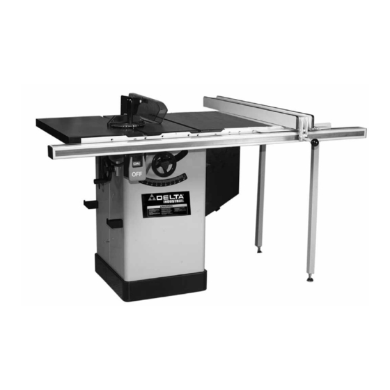
Delta 10" Hybrid Saw
(Model 36-714)
NOTE: Shown with BC30 30" Biesemeyer Fence
PART NO. A08139 - 11-12-04
Copyright © 2004 Delta Machinery
To learn more about DELTA MACHINERY
visit our website at: www.deltamachinery.com.
For Parts, Service, Warranty or other Assistance,
1-800-223-7278 (
1-800-463-3582).
please call
In Canada call
Advertisement
Table of Contents

Related Manuals for Delta 36-714


Summary of Contents for Delta 36-714
- Page 1 (Model 36-714) NOTE: Shown with BC30 30” Biesemeyer Fence PART NO. A08139 - 11-12-04 Copyright © 2004 Delta Machinery To learn more about DELTA MACHINERY visit our website at: www.deltamachinery.com. For Parts, Service, Warranty or other Assistance, 1-800-223-7278 ( 1-800-463-3582).
-
Page 2: Table Of Contents
NOT be modified and/or used for any application other than for which it was designed. If you have any questions relative to its application DO NOT use the product until you have written Delta Machinery and we have advised you. -
Page 3: Safety Guidelines
SAFETY GUIDELINES - DEFINITIONS It is important for you to read and understand this manual. The information it contains relates to protecting YOUR SAFETY and PREVENTING PROBLEMS. The symbols below are used to help you recognize this information. Indicates an imminently hazardous situation which, if not avoided, will result in death or serious injury. Indicates a potentially hazardous situation which, if not avoided, could result in death or serious injury. -
Page 4: General Safety Rules
GENERAL SAFETY RULES IMPORTANT SAFETY INSTRUCTIONS READ accessories and attachments not recommended by Delta may cause damage to the machine or injury to the user. 14. USE THE PROPER EXTENSION CORD. Make sure your extension cord is in good condition. When using PROTECTION. -
Page 5: Additional Specific Safety Rules
15. NEVER have any part of your body in line with the path of the saw blade. 16. NEVER REACH AROUND or over the saw blade. 17. NEVER attempt to free a stalled saw blade without first turning the machine “OFF”. 18. PROPERLY SUPPORT LONG OR WIDE workpieces. -
Page 6: Power Connections
POWER CONNECTIONS A separate electrical circuit should be used for your machines. This circuit should not be less than #12 wire and should be protected with a 20 Amp time lag fuse. If an extension cord is used, use only 3-wire extension cords which have 3- prong grounding type plugs and matching receptacle which will accept the machine’s plug. -
Page 7: Functional Description
This table saw has a maximum depth of cut of 3 The maximum dado width with this saw is 13/16 inch (21mm). The saw comes with two cast iron extension wings, one of three fence systems, see-through blade guard and splitter, table insert, equipment mounting hooks, a 10" diameter blade, dust port for 4"... -
Page 8: Carton Contents
19. Nylon Washer (2) 20. M5x20mm Screw (1) 21. Washer for Miter Gage (1) * Parts 8, 9 and 10 are included to attach the rear rail of the fence to the table of this saw. CARTON CONTENTS Fig. 1 Fig. 2... -
Page 9: Assembly
FOR YOUR OWN SAFETY, DO NOT CONNECT THE MACHINE TO THE POWER SOURCE UNTIL THE MACHINE IS COMPLETELY ASSEMBLED AND YOU READ AND UNDERSTAND THE ENTIRE INSTRUCTION MANUAL. THE SAW IS EXTREMELY HEAVY. HAVE TWO OR MORE PEOPLE HELP LIFT AND MOVE MACHINE AROUND DURING ASSEMBLY. ASSEMBLY... - Page 10 (D). Find the holes (E) Fig. 5 in the bottom of the saw and mark their position on the floor where you want to place the saw. Drill pilot holes in these spots and attach to floor using appropriate hardware.
- Page 11 Carefully lift motor and remove the block of wood. The weight of the motor will provide the correct tension on the belt. The belt (D) Fig. 8D is shown installed correctly as seen through the open door in the side of the saw. Fig. 8 Fig. 8A Fig. 8B...
- Page 12 Assemble left extension wing (A) Fig. 10A to the saw table. Align the three holes in the extension wing with the three holes (A) Fig. 9 in the side of the saw table. Place a 7/16" lockwasher, then a 7/16" flat washer on a 7/16- 20x1-1/4”...
-
Page 13: Installing The Switch
Assemble the fence system that comes with your saw and follow the instructions included with your fence. Be sure to locate the M8x25 bolts and M8 washers and lock washers (Nos. 8, 9 and 10 in Fig. 2) which were included in the saw package. - Page 14 USING THE SUPPLIED WRENCHES. 1. Fasten the rear splitter mounting bracket (A) Fig. 15, to the rear trunnion on the back of the saw using the two 1/4”-20 x 3/4″ hex head screws (B), 1/4” flat washers and 1/4” lock washers. Place flat washers,...
- Page 15 (L) of splitter (G); the blade guard will stay in this position. ALWAYS RETURN GUARD DOWN TO TABLE BEFORE OPERATING SAW. DO NOT OPERATE SAW WITHOUT THE TABLE INSERT AND GUARD IN PLACE. Fig. 18 Fig. 19 Fig.
-
Page 16: Saw Blade
DISCONNECT MACHINE FROM POWER SOURCE. Use a straight edge to check to see if the saw blade (B) is aligned with the rear of the splitter (G) in Figs. 24 and 25. If alignment is necessary, loosen the screws (A) Fig. - Page 17 INSTALLING TABLE INSERT DISCONNECT MACHINE FROM POWER SOURCE. Lower saw blade and install table insert (P) Fig. 26, in the saw table. IMPORTANT: When installing the table insert, make certain to hold on to the blade guard (L). The insert...
-
Page 18: Operation
STARTING AND STOPPING SAW The on/off switch is located underneath the switch shield (A) Fig. 32. To turn the saw “ON”, press the green button (B) Fig. 31 below the shield. To turn the saw “OFF”, push switch shield (A) Fig. 32. - Page 19 9. Replace blade guard and splitter before using the machine. CHECKING BLADE ALIGNMENT The saw has been aligned at the factory so the saw blade is parallel to the miter gage slots; however, it is recommended to check the alignment before initial...
- Page 20 ADJUSTING BLADE ALIGNMENT BLADE ALIGNMENT IS FACTORY SET SHOULD ADJUSTMENT. ADJUSTING BLADE ALIGNMENT IN THE FIELD IS A DIFFICULT AND TIME-CONSUMING PROCEDURE. ALL SAW BLADES HAVE SOME RUN- OUT. THEREFORE, RE-ADJUSTING ALIGNMENT SHOULD ONLY BE ATTEMPTED IF IT BECOMES NECESSARY. (SEE CHECKING BLADE ALIGNMENT.)
- Page 21 The following information describes the safe and proper method for performing the most common sawing operations. THE USE OF ATTACHMENTS AND ACCESSORIES NOT RECOMMENDED BY DELTA MAY RESULT IN THE RISK OF INJURY TO THE USER OR OTHERS.
- Page 22 Start the cut slowly and hold the work firmly against the miter gage and the table. One of the rules in running a saw is that you never hang onto or touch the part of the workpiece that will be cut off. Hold the supported piece, not the free piece that is cut off.
- Page 23 Since the work is pushed along the fence, it must have a straight edge and make solid contact with the table. THE SAW BLADE GUARD MUST BE USED. ON DELTA SAWS, THE GUARD HAS ANTI- KICKBACK FINGERS TO PREVENT KICKBACK AND A SPLITTER TO PREVENT THE WOOD KERF FROM CLOSING AND BINDING THE BLADE.
- Page 24 1 inch facing. 3. Position the wood-facing over the cutterhead with the cutterhead below the surface of the table. Turn the saw on and raise the cutterhead. The cutterhead will cut its own groove in the wood-facing. Fig. 52 shows a typical moulding operation.
- Page 25 2. Attach the dado head set (D) Fig. 56, to the saw arbor. NOTE: THE OUTSIDE ARBOR FLANGE CAN NOT BE USED WITH THE DADO HEAD SET, TIGHTEN THE ARBOR NUT AGAINST THE DADO HEAD SET BODY.
-
Page 26: Troubleshooting
Always replace the guard and splitter assembly when the non thru-sawing operation is completed. Further information on the safe and proper operation of table saws is available in the Delta “Getting the Most Out of Your Table Saw” How-To Book, Catalog No. -
Page 27: Constructing A Push Stick
CONSTRUCTING A PUSH STICK When ripping work less than 4 inches wide, a push stick should be used to complete the feed and could easily be made from scrap material by following the pattern shown in Fig. 78. -
Page 28: Maintenance
Also, check for blown fuses or open circuit breakers in the line. PARTS, SERVICE OR WARRANTY ASSISTANCE All Delta Machines and accessories are manufactured to high quality standards and are serviced by a network • of Porter-Cable Delta Factory Service Centers and Delta Authorized Service Stations. To obtain additional information regarding your Delta quality product or to obtain parts, service, warranty assistance, or the location of the nearest service outlet, please call 1-800-223-7278 (In Canada call 1-800-463-3582). -
Page 29: Accessories
Two Year Limited New Product Warranty Delta will repair or replace, at its expense and at its option, any new Delta machine, machine part, or machine accessory which in normal use has proven to be defective in workmanship or material, provided that the customer returns the product prepaid to a Delta factory service center or authorized service station with proof of purchase of the product within two years and provides Delta with reasonable opportunity to verify the alleged defect by inspection. - Page 30 NOTES...
- Page 31 NOTES...
- Page 32 Phone: (604) 420-0102 Fax: (604) 420-3522 The following are trademarks of PORTER-CABLE • DELTA (Las siguientes son marcas registradas de PORTER-CABLE • DELTA S.A.) (Les marques suivantes sont des marques de fabriquant de la PORTER-CABLE • DELTA): Auto-Set Contractor’s Saw II™, Delta ®...