
Related Manuals for GEM 1242


Summary of Contents for GEM 1242
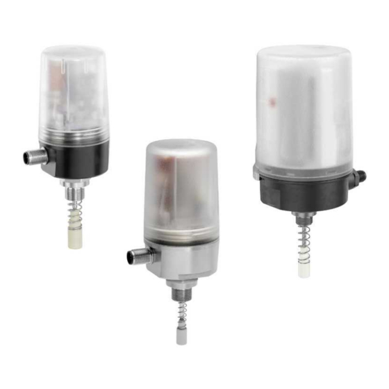
- Page 1 GEMÜ 1242 Electrical position indicator Operating instructions further information webcode: GW-1242...
- Page 2 All rights including copyrights or industrial property rights are expressly reserved. Keep the document for future reference. © GEMÜ Gebr. Müller Apparatebau GmbH & Co. KG 21.01.2022 GEMÜ 1242 2 / 41 www.gemu-group.com...
-
Page 3: Table Of Contents
14.1 Inputs ............. Product label ..........14.2 Outputs ............14.3 Switch point parameters ....... 4 GEMÜ CONEXO ............ 14.4 Error analysis ..........5 Correct use ............15 Specific data - DeviceNet ........6 Order data ............15.1 General data .......... -
Page 4: General Information
Speed Assembly and Programming, a particularly user- Hazardous situation friendly commissioning function for fast mounting, automated setting and initialization of GEMÜ products. Dependent on type, activation uses an external impulse signal or existing precautions on the device (magnetic or housing switch). -
Page 5: Safety Information
14. Do not carry out any maintenance work and repairs not de- scribed in this document without consulting the manufac- turer first. In cases of uncertainty: 15. Consult the nearest GEMÜ sales office. 3 Product description 3.1 Construction Size 1, 50 mm Size 2, 75 mm www.gemu-group.com... -
Page 6: Led Displays
A2, A3, Communica- tion error/ad- dress 0 Flashes red Device error PWR/FAULT Green SIO operation (IO-Link ver- Flashes green Communica- sion, code tion active IOL) Communica- tion error or supply voltage too low GEMÜ 1242 6 / 41 www.gemu-group.com... -
Page 7: Description
GEMÜ. The product was this document. manufactured in Germany. The GEMÜ 1242 is designed to be fitted to a GEMÜ valve in or- der to detect the position of linear actuators optically and electrically. The product has a microprocessor controlled in-... - Page 8 3. Warning label "Danger from electrostatic build-up". 4. Warning label "Do not disconnect when live". The housing must be installed protected from mechanical in- fluences. RFID chips must not be read out in potentially explosive areas. GEMÜ 1242 8 / 41 www.gemu-group.com...
-
Page 9: Order Data
Position feedback Open / Closed 6 Electrical connection M12 plug, 5-pin 7 Option Without 8 Switch Electronics 9 Connection diagram M12 plug, 5-pin 10 Travel length Potentiometer, 50 mm length 11 Special version Without www.gemu-group.com 9 / 41 GEMÜ 1242... -
Page 10: Technical Data
075: IO-Link face certificate specification V no. 125601 SIL: Product description: GEMÜ electrical position indicator 1242 Device type: Valid software version: V1.1.X.X Safety function: The fail-safe state is defined as a High (24 V DC) signal at pin 4 (device version 24 V IO-Link), if the current posi- tion of the integrated travel sensor is smaller than the switch point CLOSED (default setting 12%). - Page 11 IP NEMA 4X (UL 61010-1, UL 50E), only available as special version code Y Travel sensor: Size 1 Size 2 Minimum stroke: 2 mm 5 mm Maximum stroke: 46 mm 75 mm Hysteresis: 0.2 mm 0.5 mm Accuracy: 0.2% Full Scale www.gemu-group.com 11 / 41 GEMÜ 1242...
- Page 12 2 mm Min. switch point OPEN 0.5 mm 1.25 mm If the percentage switch points dependent on the programmed stroke are smaller than the permiss- ible min. switch points, the min. switch points apply automatically. GEMÜ 1242 12 / 41 www.gemu-group.com...
-
Page 13: Dimensions
Dimensions in mm 8.2 Size 2 WAF 20 for mounting kit M12x1, x = 9 mm WAF 24 for mounting kit M16x1, x = 11 mm depending on the valve that is used Dimensions in mm www.gemu-group.com 13 / 41 GEMÜ 1242... -
Page 14: Manufacturer's Information
2. Avoid UV rays and direct sunlight. 3. Do not exceed the maximum storage temperature (see chapter "Technical data"). 4. Do not store solvents, chemicals, acids, fuels or similar fluids in the same room as GEMÜ products and their spare parts. 10 Assembly and installation NOTICE Pay attention to the information on product labels, in ●... -
Page 15: Installing The Electrical Position Indicator On Linear Actuators
NOTICE ▶ For some valves (e.g. GEMÜ 650 and GEMÜ 687) it is ne- cessary to fit a pressure disc between the threaded ad- 1. Move the actuator to the closed position. - Page 16 4. Turn the housing clockwise to align the pneumatic or elec- trical connections. 5. Initialize the product. CAUTION Incorrect installation of the product. ▶ Damage to the housing. Only tighten the product using the spanner flats provided ● for this purpose. GEMÜ 1242 16 / 41 www.gemu-group.com...
-
Page 17: Mounting Kit Assembly (Quarter Turn Actuator)
Operating bush Compression spring 8. The product with mounting kit and stroke limiter is fully assembled. 10.3 Mounting kit assembly (quarter turn actuator) 1. Adjust the mounting bracket to the required borehole pat- tern. www.gemu-group.com 17 / 41 GEMÜ 1242... -
Page 18: Electrical Connection
The standard version of the product ● (without special function X or Y) must not be used in potentially explosive zones. Danger from sparking. Never discon- ● nect the connection cables when live. GEMÜ 1242 18 / 41 www.gemu-group.com... -
Page 19: Io-Link, Ordering Option Fieldbus Code 000, Electrical Connection Code 01
3 V DC at 100 mA Push-Pull Switching voltage Max. switching current push high drop ± 100 mA pull low drop Max. voltage drop Vdrop 3 V DC at 100 mA Switching voltage push high drop pull low drop www.gemu-group.com 19 / 41 GEMÜ 1242... -
Page 20: As-Interface, Ordering Option Fieldbus, Code A2, A3, A4
4. Connect the product in accordance with the pin assign- mechanical end positions have been changed (e.g. seal ment. replacement on the valve or actuator replacement). The initialization is retained even in the event of voltage cutoff. GEMÜ 1242 20 / 41 www.gemu-group.com... -
Page 21: Programming The End Positions
When programming via the communication interface, auto- matic programming is recommended. 12.1.1 On-site end position programming 1. Connect supply voltage. 2. Briefly (>100 ms) hold a magnet (e.g. 1242000ZMA) to the position marked PROG 1 on the housing cover. www.gemu-group.com 21 / 41 GEMÜ 1242... -
Page 22: Initialization Of The End Positions Via Io-Link
7. Programming mode is automatically terminated if the valve does not move for 5 seconds. ð The end positions are set. ð The OPEN, CLOSED and high visibility LEDs light up de- pending on the product. GEMÜ 1242 22 / 41 www.gemu-group.com... -
Page 23: End Position Programming Via Programming Input (Pin 5)
3. Open valve until end position is reached. 4. Close valve until end position is reached. 5. Programming mode is automatically terminated if the valve does not move for 5 seconds. ð The end positions are set. www.gemu-group.com 23 / 41 GEMÜ 1242... -
Page 24: Specific Data - Io-Link
Frame type in Operate: Min. cycle time: 2.3 ms Vendor-ID: Device-ID: 124201 Product-ID: 1242 IO-LINK ISDU support: SIO operation: IO-Link specification: V1.1 Note for IO-Link: IODD files can be downloaded via the hyperlinks https://ioddfinder.io-link.com/ %20oder%20www.gemu-group.com, https://ioddfinder.io-link.com or www.gemu-group.com. 13.1 Process data Device →... - Page 25 16 bit UIntegerT 0 CLOSED Programmed position 16 bit UIntegerT 0 STROKE 0x54 Last position OPEN 16 bit UIntegerT 0 Last position CLOSED 16 bit UIntegerT 0 Last position STROKE 16 bit UIntegerT 0 www.gemu-group.com 25 / 41 GEMÜ 1242...
-
Page 26: Description Of Parameter Values
High visibility position indicator on (33%) Step 4 High visibility position indicator on (66%) Error messages and location function are not affected by the setting and always remain active (100%). Programming mode Selection of programming mode. GEMÜ 1242 26 / 41 www.gemu-group.com... - Page 27 End position feedback takes place independently of the warning as long as the valve is within the set tolerance range for feedback (threshold). If the end position changes, a warning is therefore triggered first before the end position feedback is lost. www.gemu-group.com 27 / 41 GEMÜ 1242...
- Page 28 Programmed stroke Determined stroke of the linear actuator during the last correctly executed end position programming (in AD values). The change in valve stroke can be calculated in conjunction with the parameter "Last stroke". GEMÜ 1242 28 / 41 www.gemu-group.com...
- Page 29 Counter Prog error after sensor error Programming error counter/after sensor error. Counter Sensor error open Sensor error counter/OPEN position. Counter Sensor error closed Sensor error counter/CLOSED position. Counter over temperature Over-temperature counter. Actual AD-value Current value of AD converter. www.gemu-group.com 29 / 41 GEMÜ 1242...
-
Page 30: Events
14.2 Outputs Default Function Version Logic DO0, not used Setting slave in programming mode 0 = normal operation 1 = programming mode Programming mode 0 = manual programming 1 = automatic programming GEMÜ 1242 30 / 41 www.gemu-group.com... -
Page 31: Switch Point Parameters
Ordering option Fieldbus A3, A4 Parameter Switch point OPEN [%] Switch point CLOSED [%] *P0 and P1 are not used Switch points: The data in percent refer to the programmed stroke, before each end position www.gemu-group.com 31 / 41 GEMÜ 1242... -
Page 32: Error Analysis
Device status according to DeviceNet specifications Series No. Continuous serial number Name 1242 DN position indicator 1) Use EDS file in accordance with revision status of the device Note: Download EDS files from www.gemu-group.com 15.2 Net topology - DeviceNet system To avoid malfunction the trunk cable is fitted with resistors on both sides. -
Page 33: Inputs
Length Data type Access Stand- Value range value Inversion of LED colours 1 byte Boolean Get/Set 0 0 = standard 1 = inversed Inversion of signals 1 byte Boolean Get/Set 0 0 = standard 1 = inversed www.gemu-group.com 33 / 41 GEMÜ 1242... - Page 34 1 = Not calibrated 2 = No stroke 3 = Stroke < min. stroke 4 = Sensor error position closed 5 = Sensor error position open 6 = Sensor error position closed + open GEMÜ 1242 34 / 41 www.gemu-group.com...
- Page 35 3 = Stroke reduction position closed + open Valve cycles user 4 bytes UDINT Get/Set 0 Can be reset to 0, display of numerical values 0–429496729 Valve cycles total 4 bytes UDINT Display of numerical values 0–429496729 www.gemu-group.com 35 / 41 GEMÜ 1242...
-
Page 36: Troubleshooting
17.1 Spare parts Currently the pro- (see "Technical cess valve is in the data") No spare parts are available for this product. If it is faulty, valid sensor range. please return it to GEMÜ for repair. GEMÜ 1242 36 / 41 www.gemu-group.com... -
Page 37: Disassembly
Returned goods can be processed only when this note is completed. If no return delivery note is included with the product, GEMÜ cannot process credits or repair work but will dispose of the goods at the operator's expense. -
Page 38: Declaration Of Incorporation According To 2006/42/Ec (Machinery Directive)
21 Declaration of Incorporation according to 2006/42/EC (Machinery Directive) 21 Declaration of Incorporation according to 2006/42/EC (Machinery Directive) GEMÜ 1242 38 / 41 www.gemu-group.com... -
Page 39: Declaration Of Conformity According To 2014/30/Eu (Emc Directive)
22 Declaration of conformity according to 2014/30/EU (EMC Directive) 22 Declaration of conformity according to 2014/30/EU (EMC Directive) www.gemu-group.com 39 / 41 GEMÜ 1242... -
Page 40: Declaration Of Conformity In Accordance With 2014/34/Eu (Atex)
23 Declaration of Conformity in accordance with 2014/34/EU (ATEX) 23 Declaration of Conformity in accordance with 2014/34/EU (ATEX) GEMÜ 1242 40 / 41 www.gemu-group.com... - Page 41 GEMÜ Gebr. Müller Apparatebau GmbH & Co. KG Fritz-Müller-Straße 6-8, 74653 Ingelfingen-Criesbach, Germany Subject to alteration Phone +49 (0) 7940 1230 · info@gemue.de www.gemu-group.com 01.2022 | 88796460...