
Related Manuals for GEM 1240


Summary of Contents for GEM 1240
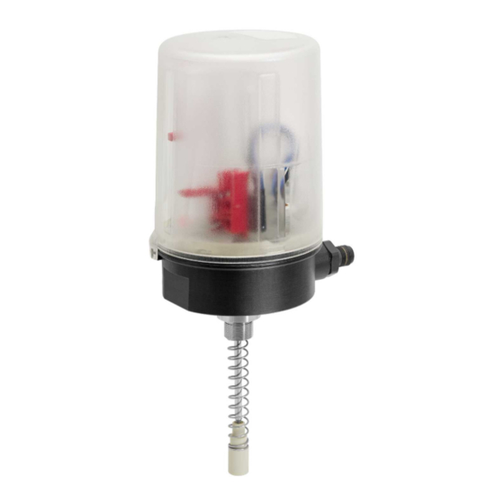
- Page 1 GEMÜ 1240 Electrical position indicator Operating instructions further information webcode: GW-1240...
- Page 2 All rights including copyrights or industrial property rights are expressly reserved. Keep the document for future reference. © GEMÜ Gebr. Müller Apparatebau GmbH & Co. KG 24.05.2022 GEMÜ 1240 2 / 18 www.gemu-group.com...
-
Page 3: Table Of Contents
2 Safety information ..........3 Product description ..........Construction ..........Description ............. Function ............Product label ..........4 GEMÜ CONEXO ............ 5 Correct use ............6 Order data ............Order codes ........... Order example ..........7 Technical data ............. 8 Dimensions ............ -
Page 4: General Information
▶ Non-observance can cause moderate 6. Define the areas of responsibility. to light injury. 7. Observe the safety data sheets. 8. Observe the safety regulations for the media used. GEMÜ 1240 4 / 18 www.gemu-group.com... -
Page 5: Product Description
Traceability number Serial number 3 Product description The month of manufacture is encoded in the traceability num- ber and can be obtained from GEMÜ. The product was manu- 3.1 Construction factured in Germany. The manufacturing month is coded under the traceability number and can be requested from GEMÜ. -
Page 6: Correct Use
The product is not intended for use in potentially explosive areas. The product is designed for fitting to a GEMÜ valve in order to detect the position of linear actuators electrically. It is non- positively connected with the actuator spindle by means of a mounting kit (spring, operating bush). -
Page 7: Order Data
7 Option Without 8 Switch Change-over contact, microswitch, 24 V DC, 250 V AC Crouzet, V4S, SPDT 9 Connection diagram Microswitch, change-over contact, SPDT 10 Travel sensor version Potentiometer, 75 mm length 11 CONEXO Without www.gemu-group.com 7 / 18 GEMÜ 1240... -
Page 8: Technical Data
10 to 30 V DC Current consumption: Switch Code M1 Code N1 Code P1 for DC: 5 mA to 5 A ≥ 3 mA (undamped) 0–200 mA for AC: 100 mA to 6 A ≤ 1 mA (damped) GEMÜ 1240 8 / 18 www.gemu-group.com... -
Page 9: Dimensions
8 Dimensions 8 Dimensions Ø 90 Square 86,5 SW 24 Dimensions in mm www.gemu-group.com 9 / 18 GEMÜ 1240... -
Page 10: Manufacturer's Information
"Technical data"). Spring Screws 4. Do not store solvents, chemicals, acids, fuels or similar Operating bush Pressure disc* fluids in the same room as GEMÜ products and their spare parts. Distance piece O-ring* O-ring O-ring* 10 Assembly and installation Adapter 1. - Page 11 NOTICE ▶ For some valves (e.g. GEMÜ 650 and GEMÜ 687) it is ne- cessary to fit a pressure disc between the threaded ad- apter and the actuator head. This is included in the re- quired mounting kits, sometimes with an additional O-ring (only GEMÜ...
- Page 12 4. Turn the housing clockwise to align the pneumatic or elec- trical connections. 5. Set the switch on the product. CAUTION Incorrect installation of the product. ▶ Damage to the housing. Only tighten the product using the spanner flats provided ● for this purpose. GEMÜ 1240 12 / 18 www.gemu-group.com...
- Page 13 6. Release red levers 3. 10. Release red levers 5. ð Switch 4 engages. ð Switch 6 engages. ð The upper switching ð The lower switching po- position is set. sition is set. 11. Make the electrical connection. www.gemu-group.com 13 / 18 GEMÜ 1240...
-
Page 14: Electrical Connection
11.1.1 Connection diagram CLOSED OPEN 11.2 2-wire NAMUR proximity switch, ordering option Connection diagram code N1 11.2.1 Connection diagram CLOSED OPEN 11.3 3-wire proximity switch, ordering option Connection diagram code P1 11.3.1 Connection diagram OPEN CLOSED GEMÜ 1240 14 / 18 www.gemu-group.com... -
Page 15: Troubleshooting
If base the cables if neces- no return delivery note is included with the product, GEMÜ sary cannot process credits or repair work but will dispose of the goods at the operator's expense. -
Page 16: Declaration Of Incorporation According To 2006/42/Ec (Machinery Directive)
17 Declaration of Incorporation according to 2006/42/EC (Machinery Directive) 17 Declaration of Incorporation according to 2006/42/EC (Machinery Directive) GEMÜ 1240 16 / 18 www.gemu-group.com... -
Page 17: Declaration Of Conformity According To 2014/30/Eu (Emc Directive)
18 Declaration of conformity according to 2014/30/EU (EMC Directive) 18 Declaration of conformity according to 2014/30/EU (EMC Directive) www.gemu-group.com 17 / 18 GEMÜ 1240... - Page 18 GEMÜ Gebr. Müller Apparatebau GmbH & Co. KG Fritz-Müller-Straße 6-8, 74653 Ingelfingen-Criesbach, Germany Subject to alteration Phone +49 (0) 7940 1230 · info@gemue.de www.gemu-group.com 05.2022 | 88729239...