
Related Manuals for GEM 1241


Summary of Contents for GEM 1241
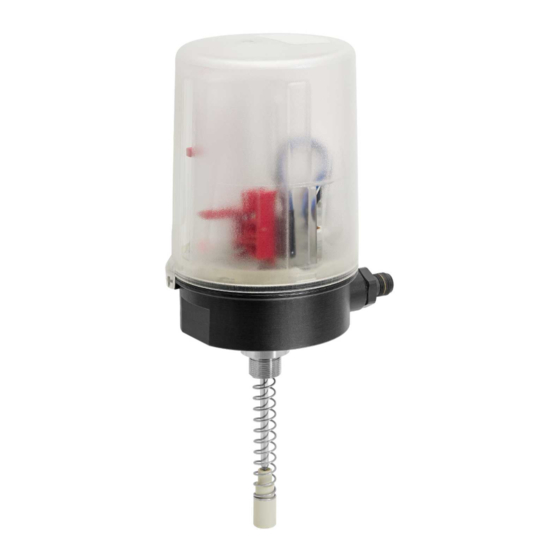
- Page 1 GEMÜ 1241 Electrical position indicator Operating instructions further information webcode: GW-1241...
- Page 2 All rights including copyrights or industrial property rights are expressly reserved. Keep the document for future reference. © GEMÜ Gebr. Müller Apparatebau GmbH & Co. KG 19.10.2023 GEMÜ 1241 2 / 20 www.gemu-group.com...
-
Page 3: Table Of Contents
Information ............ Symbols used ..........Warning notes ..........2 Safety information ..........3 Product description ..........Function ............4 GEMÜ CONEXO ............ 5 Correct use ............6 Order data ............7 Technical data ............. 8 Dimensions ............9 Manufacturer's information ........ -
Page 4: General Information
- Local safety regulations which must be adhered to by the Potentially dangerous situation! operator and by any additional installation personnel. ▶ Non-observance can cause death or severe injury. CAUTION Potentially dangerous situation! ▶ Non-observance can cause moderate to light injury. GEMÜ 1241 4 / 20 www.gemu-group.com... -
Page 5: Product Description
5. Ensure that the contents of the document have been fully 3.3 Function understood by the responsible personnel. The GEMÜ 1241 electrical position indicator is used to feed 6. Define the areas of responsibility. back and verify the position of valves operated with pneu- 7. -
Page 6: Gemü Conexo
4 GEMÜ CONEXO 4 GEMÜ CONEXO ATEX Gas: II 2G Ex ib IIB T4 Gb Order variant Dust: II 2D Ex ib IIIC T120°C Db In the corresponding design with CONEXO, this product has an RFID chip (1) for electronic identification purposes. The po- EC type examination certificate: IBExU21ATEX1097 X sition of the RFID chip can be seen below. -
Page 7: Order Data
5 Device version Open 6 Electrical connection M16 Skintop cable gland 7 Option Without 8 Switch Proximity switch, 2-wire, NAMUR P+F, NJ1,5-6,5-15-N-Y180094 9 Connection diagram Terminals, NAMUR 10 Travel sensor version Potentiometer, 75 mm length www.gemu-group.com 7 / 20 GEMÜ 1241... -
Page 8: Technical Data
Current consumption: ≤ 0.1 mA (damped) ≥ 3 mA (undamped) Intrinsically safe charac- Ui = 16 V teristic values: Ii = 52 mA Pi = 169 mW Li = 50 µH Ci = 30 nF GEMÜ 1241 8 / 20 www.gemu-group.com... -
Page 9: Dimensions
8 Dimensions 8 Dimensions Ø 90 86,5 SW 24 Dimensions in mm www.gemu-group.com 9 / 20 GEMÜ 1241... -
Page 10: Manufacturer's Information
2. Place O-rings 1 and 2 into threaded adapter 3. 4. Do not store solvents, chemicals, acids, fuels or similar 3. Screw threaded adapter 3 into the actuator opening as far fluids in the same room as GEMÜ products and their spare as it will go and tighten. parts. - Page 11 10 Assembly and installation NOTICE ▶ For some valves (e.g. GEMÜ 650 and GEMÜ 687) it is ne- cessary to fit a pressure disc between the threaded ad- apter and the actuator head. This is included in the re- quired mounting kits, sometimes with an additional O-ring (only GEMÜ...
-
Page 12: Assembling The Stroke Limiter (Linear Actuator)
4. Turn the housing clockwise to align the pneumatic or elec- trical connections. 5. Initialize the product. CAUTION Incorrect installation of the product. ▶ Damage to the housing. Only tighten the product using the spanner flats provided ● for this purpose. GEMÜ 1241 12 / 20 www.gemu-group.com... -
Page 13: Preparations For Assembly To The Valve (Quarter Turn Actuator)
Only tighten the product using the spanner flats provided ● for this purpose. 2. Remove the screw 1 from the trigger cam 2. 10.7 NAMUR sizes, quarter turn actuator, PTAZ The following borehole patterns are available: 80 x 30 x 20 www.gemu-group.com 13 / 20 GEMÜ 1241... - Page 14 17. If the settings need to be readjusted, switch off power to the product again and repeat the steps in "Setting the switching positions". Setting the upper switching Setting the lower switching position: position: GEMÜ 1241 14 / 20 www.gemu-group.com...
-
Page 15: Electrical Connection
11.2 M12 plug, 5-pin (code 01) 11.2.1 Connection diagram - NAMUR (code N2) Signal name L+, OPEN switch L-, OPEN switch L+, CLOSED switch L-, CLOSED switch n.c. * *Pin 5 is not connected. www.gemu-group.com 15 / 20 GEMÜ 1241... -
Page 16: Troubleshooting
If Exceptional maintenance work! no return delivery note is included with the product, GEMÜ ▶ Damage to the GEMÜ product cannot process credits or repair work but will dispose of the Any maintenance work and repairs not described in these ●... -
Page 17: Declaration Of Incorporation According To 2006/42/Ec (Machinery Directive)
17 Declaration of Incorporation according to 2006/42/EC (Machinery Directive) 17 Declaration of Incorporation according to 2006/42/EC (Machinery Directive) www.gemu-group.com 17 / 20 GEMÜ 1241... -
Page 18: Declaration Of Conformity According To 2014/30/Eu (Emc Directive)
18 Declaration of conformity according to 2014/30/EU (EMC Directive) 18 Declaration of conformity according to 2014/30/EU (EMC Directive) GEMÜ 1241 18 / 20 www.gemu-group.com... -
Page 19: Declaration Of Conformity In Accordance With 2014/34/Eu (Atex)
19 Declaration of Conformity in accordance with 2014/34/EU (ATEX) 19 Declaration of Conformity in accordance with 2014/34/EU (ATEX) www.gemu-group.com 19 / 20 GEMÜ 1241... - Page 20 GEMÜ Gebr. Müller Apparatebau GmbH & Co. KG Fritz-Müller-Straße 6-8, 74653 Ingelfingen-Criesbach, Germany Subject to alteration Phone +49 (0) 7940 1230 · info@gemue.de www.gemu-group.com 10.2023 | 88729327...