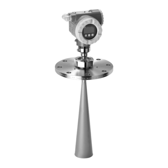
Endress+Hauser Micropilot S FMR540 Operating Instructions Manual
Level-radar
Hide thumbs
Also See for Micropilot S FMR540:
- Operating instructions manual (80 pages) ,
- Brief operating instructions (44 pages) ,
- Technical information (36 pages)

Related Manuals for Endress+Hauser Micropilot S FMR540


Summary of Contents for Endress+Hauser Micropilot S FMR540
- Page 1 Products Solutions Services BA00326F/00/EN/14.13 71229236 Valid as of software version: V 01.01.xx (amplifier) V 01.01.xx (communication) Operating Instructions Micropilot S FMR540 Level-Radar...
- Page 2 Brief operating instructions Micropilot S FMR540 - Brief operating instructions KA255F/00/a2/09.06 52027735 Contrast: measured set value value Group selection process empty check basic tank tank medium full pipe dist./ range of dist./ setup shape shape cond. cond. calibr. calibr. diameter...
-
Page 3: Table Of Contents
Installation conditions ..... 11 Contact addresses of Endress+Hauser ..71 Installation instructions ....15 Post-installation check . -
Page 4: Safety Instructions
Safety instructions Micropilot S FMR540 4 to 20 mA HART Safety instructions Designated use The Micropilot S is a compact radar level transmitter for the continuous, contactless measurement of predominantly solids. The device can also be freely mounted outside closed metal vessels because of its operating frequency in the K-band and a maximum radiated pulsed energy of 1 mW (average power output 1 μW). -
Page 5: Notes On Safety Conventions And Symbols
Micropilot S FMR540 4 to 20 mA HART Safety instructions Notes on safety conventions and symbols In order to highlight safety-relevant or alternative operating procedures in the manual, the following conventions have been used, each indicated by a corresponding symbol in the margin. - Page 6 Safety instructions Micropilot S FMR540 4 to 20 mA HART 1.4.4 Symbols for certain types of information Symbol Meaning Allowed Indicates procedures, processes or actions that are allowed. A0011182 Forbidden Indicates procedures, processes or actions that are forbidden. A0011184 Indicates additional information.
-
Page 7: Identification
Micropilot S FMR540 4 to 20 mA HART Identification Identification Device designation 2.1.1 Nameplate Device nameplate The following technical data are given on the device nameplate: ENDRESS+HAUSER Made in Germany MICROPILOT S D-79689 Maulburg Order Code: Ser.-No.: PN max. max. - Page 8 Identification Micropilot S FMR540 4 to 20 mA HART PTB type plate Hersteller / Producer : ENDRESS+HAUSER MICROPILOT S FMR Baujahr Year of constr. Tankreferenzhöhe Tank reference height Tank-Nr. Tank-no. Zert.Messbereich/Cert.Measuring range Umgeb./Environm. °C from A0020446 Note! The fields are only filled if in feature "70" "Weight + measures approval" the variant "G" is selected.
-
Page 9: Scope Of Delivery
The device complies with the applicable standards and regulations as listed in the EC declaration of conformity and thus complies with the statutory requirements of the EG directives. Endress+Hauser confirms the successful testing of the device by affixing to it the CE mark. -
Page 10: Installation
Installation Micropilot S FMR540 4 to 20 mA HART Installation Quick installation guide ° A0020810 Marker at sensor Marker at flange Incoming acceptance, transport, storage 3.2.1 Incoming acceptance Check the packing and contents for any signs of damage. Check the shipment, make sure nothing is missing and that the scope of supply matches your order. -
Page 11: Installation Conditions
Micropilot S FMR540 4 to 20 mA HART Installation Installation conditions 3.3.1 Engineering hints Orientation • Recommended distance (1) wall - outer edge of nozzle: ~1/6 of tank diameter ("Beam angle", ä 12). • Not in the centre (3), interference can cause signal loss. - Page 12 Installation Micropilot S FMR540 4 to 20 mA HART Beam angle The beam angle is defined as the angle where the energy density of the radar waves reaches half the value of the maximum energy density (3dB-width). Microwaves are also emitted outside the signal beam and can be reflected off interfering installations.
- Page 13 Micropilot S FMR540 4 to 20 mA HART Installation Measuring conditions • The measuring range begins, where the beam hits the tank bottom. Particularly with dish bottoms or conical outlets the level cannot be detected below this point. • Depending on its consistence, foam can either absorb microwaves or reflect them off the foam surface.
- Page 14 Installation Micropilot S FMR540 4 to 20 mA HART Measuring range The usable measuring range depends on the size of the antenna, the reflectivity of the medium, the mounting location and eventual interference reflections. To achieve an optimised signal strength it is recommended to use an antenna with as large as possible diameter (DN200(8") or DN250 (10") parabolic antenna).
-
Page 15: Installation Instructions
Micropilot S FMR540 4 to 20 mA HART Installation Installation instructions 3.4.1 Mounting kit For the mounting , you will require the following tool: • The tool for flange mounting • 90 mm wrench for adjustment of the alignment device (only for devices with alignment device) •... - Page 16 Installation Micropilot S FMR540 4 to 20 mA HART Standard installation FMR540 with horn antenna • Observe installation instructions, ä 11. • Marker must be aligned towards tank wall. The marker is located clearly visible on the sensor neck or the flange.
- Page 17 Micropilot S FMR540 4 to 20 mA HART Installation Standard installation FMR540 with parabolic antenna • Observe installation instructions, ä 11. • Marker is aligned towards tank wall. The marker is located clearly visible on the sensor neck or the flange.
- Page 18 Installation Micropilot S FMR540 4 to 20 mA HART FMR540 with alignment device Micropilot S should be installed vertically towards the Liquid surface for best measuring performance of ±1 mm (0.04 in). Using the alignment device it is possible to tilt the antenna axis by up to 15°...
- Page 19 Micropilot S FMR540 4 to 20 mA HART Installation Sensor alignment tool for alignment device A sensor alignment tool (1) is recommended to be used at the time of installation for FMR540 with alignment device. Alignment procedure This procedure is only applicable to the sensors purchased with alignment device (3).
- Page 20 Installation Micropilot S FMR540 4 to 20 mA HART Place the Sensor alignment tool (1) for Micropilot S FMR540. Please, note to avoid any obstacles between the backside of the Alignment tool and the nameplate of Micropilot S FMR540. °...
- Page 21 Micropilot S FMR540 4 to 20 mA HART Installation Sealing for custody transfer applications The alignment device can be sealed using the provided slotted capstan screws. The seal wires must be installed against the open direction in order to assure that a loosening of the alignment device is not possible.
- Page 22 Installation Micropilot S FMR540 4 to 20 mA HART 3.4.4 Endress+Hauser UNI flange The number of bolts has sometimes been reduced. The bolt-holes have been enlarged for adaption of dimensions, therefore, the flange needs to be properly aligned to the counterflange before the bolts are tightened.
-
Page 23: Post-Installation Check
Micropilot S FMR540 4 to 20 mA HART Installation 3.4.5 Alignment unit with Endress+Hauser UNI flange A0020791 Dimensions: mm (in) Viton-Dichtung Endress+Hauser UNI Flange DN200/DN250 Please, also see sensor alignment tool ä 63. Post-installation check After the measuring device has been installed, perform the following checks: •... -
Page 24: Wiring
Wiring Micropilot S FMR540 4 to 20 mA HART Wiring Quick wiring guide When grounding conductive screens, the corresponding directives EN 60079-14 and EN 1127-1 must be observed. Recommendation for safe grounding of conductive screens: CAUTION Before connection please note the following: ‣... - Page 25 Micropilot S FMR540 4 to 20 mA HART Wiring 4.1.2 Wiring with Tank Side Monitor NRF590 CAUTION Before connection please note the following: ‣ Make sure you use the specified cable gland. ‣ Befor removing housing cover at seperate connection compartment turn off the power supply! Insert cable through gland .
-
Page 26: Connecting The Measuring Unit
Wiring Micropilot S FMR540 4 to 20 mA HART Connecting the measuring unit Terminal compartment The housing features a separate terminal compartment. A0020471 Power supply Signal Load HART Minimum load for HART communication: 250 Cable entry Description Feature Option model... - Page 27 – The cable shall be protected e.g. routed in an armoured hose. Power supply • For stand alone operation via two Endress+Hauser RN221N. • Integrated in tank gauging system via Endress+Hauser Tank Side Monitor NRF590 (recommended operation mode). Highly accurate measurement For highly accurate measurements the measured variable must be transmitted using HART protocol to ensure the necessary resolution.
- Page 28 Wiring Micropilot S FMR540 4 to 20 mA HART 4.2.2 HART connection with two Endress+Hauser RN221N ≥ Ω 4...20 mA A0020488 Commubox FXA291 (USB) Power supply ToF Adapter FXA291 FieldCare Signal VIATOR Bluetooth modem with connecting cable Field Communicator 475...
-
Page 29: Recommended Connection
Micropilot S FMR540 4 to 20 mA HART Wiring Recommended connection 4.3.1 Equipotential bonding Connect the Equipotential bonding to the external ground terminal of the transmitter. 4.3.2 Wiring screened cable CAUTION In Ex applications, the device must only be grounded on the sensor side. Further safety instructions are given in the separate documentation for applications in explosion hazardous areas. -
Page 30: Operation
Operation Micropilot S FMR540 4 to 20 mA HART Operation Quick operation guide ENDRESS + HAUSER E S C – E S C E S C E S C >3 s Basic setup Tank shape medium property Return to group... - Page 31 Micropilot S FMR540 4 to 20 mA HART Operation 5.1.1 General structure of the operating menu The operating menu is made up of two levels: • Function groups (00, 01, 03, …, 0C, 0D): The individual operating options of the device are split up roughly into different function groups.
-
Page 32: Display And Operating Elements
Operation Micropilot S FMR540 4 to 20 mA HART Display and operating elements ENDRESS + HAUSER – A0020494-EN LCD (liquid crystal display) Red LED Symbols Green LED Operating keys Custody locking switch Snap-fit Sealing pin NOTICE To access the display the cover of the electronic compartment may be removed even in hazardous area. - Page 33 Micropilot S FMR540 4 to 20 mA HART Operation 5.2.2 Display symbols The following table describes the symbols that appear on the liquid crystal display: Symbols Meaning ALARM_SYMBOL This alarm symbol appears when the device is in an alarm state. If the symbol flashes, this indicates a warning.
- Page 34 Operation Micropilot S FMR540 4 to 20 mA HART 5.2.3 Key assignment The operating elements are located inside the housing and are accessible for operation by opening the lid of the housing. Function of the keys Key(s) Meaning • Navigate upwards in the selection list.
-
Page 35: Local Operation
Micropilot S FMR540 4 to 20 mA HART Operation Local operation 5.3.1 Locking of the configuration mode The Micropilot can be protected in two ways against unauthorised changing of device data, numerical values or factory settings: Function "unlock parameter" (0A4): A value <>... - Page 36 There is no need to change these parameters under normal circumstances and consequently, they are protected by a special code known only to the Endress+Hauser service organization. Please contact Endress+Hauser if you have any questions.
- Page 37 Micropilot S FMR540 4 to 20 mA HART Operation 5.3.3 Factory settings (Reset) CAUTION A reset sets the device back to the factory settings. This can lead to an impairment of the measurement. Generally, you should perform a basic setup again following a reset.
-
Page 38: Display And Acknowledging Error Messages
Operation Micropilot S FMR540 4 to 20 mA HART Display and acknowledging error messages Type of error Errors that occur during commissioning or measuring are displayed immediately on the local display. If two or more system or process errors occur, the error with the highest priority is shown on the display. -
Page 39: Hart Communication
Micropilot S FMR540 4 to 20 mA HART Operation HART communication Apart from local operation, you can also parameterise the measuring device and view measured values by means of a HART protocol. The following operating options are available: • Operation via the universal handheld operating unit, the Field Communicator 475 •... - Page 40 Operation with Endress+Hauser operating program FieldCare is an Endress+Hauser asset management tool based on FDT technology. With FieldCare, you can configure all Endress+Hauser devices as well as devices from other manufacturers that support the FDT standard. Hardware and software requirements you can find on the internet: www.endress.com »...
- Page 41 Micropilot S FMR540 4 to 20 mA HART Operation Signal analysis via envelope curve A0021212-EN Tank linearization A0021213-EN Endress+Hauser...
-
Page 42: Commissioning
Commissioning Micropilot S FMR540 4 to 20 mA HART Commissioning Function check Make sure that all final checks have been completed before you start up your measuring point: • Checklist "Post installation check", ä 23. • Checklist "Post connection check", ä 29. -
Page 43: Basic Setup
Micropilot S FMR540 4 to 20 mA HART Commissioning Basic Setup Tank shape flat ceiling Measuring cond. unknown 100% Process cond. standard Empty calibr. Full calibr. Empty calibr. (=zero); settings in 005 Distance (distance flange/product); display in 0A5 Safety settings; settings in 015 Full calibr. - Page 44 Commissioning Micropilot S FMR540 4 to 20 mA HART CAUTION The basic setup is sufficient for successful commissioning in most applications. Complex measuring operations necessitate additional functions that the user can use to customise the Micropilot as necessary to suit his specific requirements.
-
Page 45: Basic Setup With The Device Display Vu331
Micropilot S FMR540 4 to 20 mA HART Commissioning Basic Setup with the device display VU331 Function "measured value" (000) On-site display Meaning measured value This function displays the current measured value in the selected unit (see "customer unit" (042)) function). The 63.455 %... - Page 46 Commissioning Micropilot S FMR540 4 to 20 mA HART A0020493 Dome ceiling horizontal cyl Flat ceiling Sphere Bypass Stilling well Function "medium property" (003), liquids only On-site display Meaning medium property This function is used to select the dielectric constant.
- Page 47 Micropilot S FMR540 4 to 20 mA HART Commissioning Function "process cond." (004), liquids only On-site display Meaning process cond. This function is used to select the process conditions. standard calm surfaces. turb. surface Further options: • Standard • Calm surface •...
- Page 48 Commissioning Micropilot S FMR540 4 to 20 mA HART Function "empty calibr." (005) On-site display Meaning empty calibr. This function is used to enter the distance from the flange (reference point of the measurement) to the minimum level 5.000 (= zero).
- Page 49 Micropilot S FMR540 4 to 20 mA HART Commissioning Function "full calibr." (006) On-site display Meaning full calibr. This function is used to enter the distance from the minimum level to the maximum level (= span). In principle, it is 5.000...
- Page 50 Commissioning Micropilot S FMR540 4 to 20 mA HART Function "pipe diameter" (007) On-site display Meaning pipe diameter This function is used to enter the pipe diameter of the stilling well or bypass pipe. 204.425 inner diameter of bypass/stilling well...
- Page 51 Micropilot S FMR540 4 to 20 mA HART Commissioning Function "check distance" (051) On-site display Meaning check disttance This function triggers the mapping of interference echoes. To do so, the measured distance must be compared with the dist. unknown actual distance to the product surface.
- Page 52 Commissioning Micropilot S FMR540 4 to 20 mA HART CAUTION The range of mapping must end 0.5 m (1.6 ft) before the echo of the actual level. For an empty tank, do not enter E, but E – 0.5 m (1.6 ft). If a mapping already exists, it is overwriten up to the distance specified in "range of mapping"...
- Page 53 Micropilot S FMR540 4 to 20 mA HART Commissioning Function "set value" (009) On-site display Meaning set value This function enables the user to offset the difference between the reference level and the measured level 3.000 (or between ullage value and measured distance). To make...
- Page 54 Commissioning Micropilot S FMR540 4 to 20 mA HART 6.4.2 Envelope curve with the device display VU331 After the basic setup, an evaluation of the measurement with the aid of the envelope curve (function group "envelope curve" (0E)) is recommended.
- Page 55 Micropilot S FMR540 4 to 20 mA HART Commissioning Function "envelope curve display" (0E3) The envelope curve is displayed in this function. You can use it to obtain the following information: A0021046 Envelope curve only Envelope curve and interference echo suppression (map) Full calibr.
- Page 56 Commissioning Micropilot S FMR540 4 to 20 mA HART Move mode Then press to switch to Move mode. Either is displayed. • shifts the curve to the right. • shifts the curve to the left. A0021579 Vertical Zoom mode Press once more to switch to Vertical Zoom mode.
-
Page 57: Basic Setup With The Endress+Hauser Operating Program
Basic Setup with the Endress+Hauser operating program To carry out the basic setup with the Endress+Hauser operating program, proceed as follows: • Start the operating program and establish a connection. • Select the "basic setup" function group in the navigation bar. - Page 58 Commissioning Micropilot S FMR540 4 to 20 mA HART Basic Setup step 2/5: • Enter the application parameters: – Tank shape – Medium property – Process cond. A0021200-EN Basic Setup step 3/5: If "dome ceiling" is selected in the "tank shape" function, the following display appears on the screen: •...
- Page 59 Micropilot S FMR540 4 to 20 mA HART Commissioning If "horizontal cyl" or "sphere" is selected in the "tank shape" function, the following display appears on the screen: • Empty calibr. • Full calibr. A0021202-EN If "stilling well" or "bypass" is selected in the "tank shape" function, the following display appears on the screen: •...
- Page 60 Commissioning Micropilot S FMR540 4 to 20 mA HART If "flat ceiling" is selected in the "tank shape" function, the following display appears on the screen: • Empty calibr. • Full calibr. A0021204-EN Basic Setup step 4/5: • This step starts the tank mapping •...
- Page 61 Micropilot S FMR540 4 to 20 mA HART Commissioning 6.5.1 Signal analysis via envelope curve After the basic setup, an evaluation of the measurement using the envelope curve is recommended. A0021206-EN 6.5.2 User-specific applications (operation) For details of setting the parameters of user-specific applications, see separate documentation BA00341F/00/EN "Description of Instrument Functions"...
-
Page 62: Maintenance
• Carry out repairs according to the instructions. On completion of repairs, carry our the specifiedroutine test on the device. • Only Endress+Hauser Service may convert a certified device into a different certified variant. • Document all repair work and conversions. -
Page 63: Accessories
Micropilot S FMR540 4 to 20 mA HART Accessories Accessories Various accessories, which can be ordered separately from Endress+Hauser, are available for the Micropilot S. Weather protection cover A weather protective cover made of stainless steel is available for outdoor mounting (order code: 543199-0001). -
Page 64: Commubox Fxa195 Hart
Commubox FXA291 The Commubox FXA291 connects Endress+Hauser field devices with CDI interface (= Endress+Hauser Common Data Interface) to the USB interface of a personal computer or a notebook. For details refer to TI00405C/07/EN. For the device you need the "ToF Adapter FXA291" as an additional accessory. -
Page 65: Trouble-Shooting
Micropilot S FMR540 4 to 20 mA HART Trouble-shooting Trouble-shooting Trouble-shooting instructions Check voltage and Not ok compare it with the Instrument does Connect the Instrument works? Ready specifications on the not respond correct voltage nameplate. Check the polarity Not ok Correct the polarity of the voltage. -
Page 66: System Error Messages
Trouble-shooting Micropilot S FMR540 4 to 20 mA HART System error messages Code Description Possible cause Remedy A102 checksum error device has been powered off before reset; general reset & new data could be stored; avoid emc problem; calibr.required emc problem;... - Page 67 Micropilot S FMR540 4 to 20 mA HART Trouble-shooting Code Description Possible cause Remedy W601 linearisation ch1 curve linearization not monotonously correct linearisation table not monotone increasing W611 less than 2 linearisation number of entered linearization points correct linearisation table points for channel 1 <...
-
Page 68: Application Errors
Trouble-shooting Micropilot S FMR540 4 to 20 mA HART Application errors Error Output Possible cause Remedy A warning or Depending on the configuration See table of error 1. See table of error messages alarm has occurred messages ( ä 66) (... - Page 69 Micropilot S FMR540 4 to 20 mA HART Trouble-shooting Error Output Possible cause Remedy If the surface is not Signal is weakened by 1. Carry out tank mapping calm (e.g. filling, the rough surface – the basic setup emptying, agitator...
-
Page 70: Spare Parts
• Can be read out via the "Serial number" parameter in the "Device information" submenu.. Return The following procedures must be carried out before a transmitter is sent to Endress+Hauser e.g. for repair or calibration: • Remove all residue which may be present. Pay special attention to the gasket grooves and crevices where fluid may be present. -
Page 71: Disposal
Rev. 1, DD 1. 07.2009 V 01.01.02 Adaptation parabolic antenna Contact addresses of Endress+Hauser The addresses of Endress+Hauser are given on the back cover of this operating manual. If you have any questions, please do not hesitate to contact your Endress+Hauser representative. Endress+Hauser... -
Page 72: Technical Data
Technical data Micropilot S FMR540 4 to 20 mA HART Technical data 10.1 Additional technical data For the technical data, please refer to the Technical Information TI00412F/00/EN. 10.1.1 Supplementary Documentation Supplementary Documentation • Technical Information (TI00412F/00/EN) • Operating Instructions "Description of Instrument functions" (BA00341F/00/EN) •... - Page 73 Micropilot S FMR540 4 to 20 mA HART Technical data Endress+Hauser...
-
Page 74: Appendix
Appendix Micropilot S FMR540 4 to 20 mA HART Appendix 11.1 Operating menu HART (display modul) basic setup tank shape medium cond. process cond. empty calibr. full calibr. dome ceiling unknown standard enter value enter value horizontal cyl. DK: < 1.9 calm surface DK: 1.9 …... - Page 75 Micropilot S FMR540 4 to 20 mA HART Appendix dist./meas.value check distance range of mapping start mapping dist./meas.value set value distance = ok input of D and L dist. too small mapping range are displayed manual D and L are displayed dist.
- Page 76 Appendix Micropilot S FMR540 4 to 20 mA HART envelope curve plot settings recording curve envelope curve single curve env.curve+FAC cyclic env.curve+cust.map display language back to home format display no. of decimals enter time decimal default: 100 s 1/16” x.xx x.xxx...
- Page 77 Micropilot S FMR540 4 to 20 mA HART Appendix display test sep. character . point , comma measured dist. measured level detection window application par. not modified modified reset distance unit download mode A0021610-EN Endress+Hauser...
-
Page 78: Index
Micropilot S FMR540 4 to 20 mA HART Index Accessories ........63 Key assignment . - Page 79 Micropilot S FMR540 4 to 20 mA HART Unlock parameter ......35–36 VU331........45, 54 Warning .
- Page 80 71229236 www.addresses.endress.com...