Endress+Hauser Micropilot S FMR540 Safety Instructions
Hide thumbs
Also See for Micropilot S FMR540:
- Operating instructions manual (80 pages) ,
- Brief operating instructions (44 pages) ,
- Technical information (36 pages)
Advertisement
Available languages
Available languages
Quick Links
XA00338F-D/00/A3/13.16
71314016
0
Products
Safety Instructions
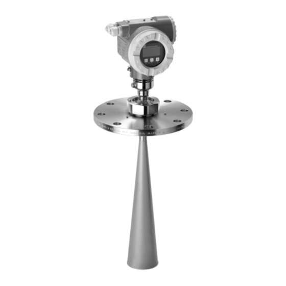
Micropilot S
FMR540
4-20 mA HART
ATEX: II 1/2 G Ex ia IIC T6...T1 Ga/Gb
II 2 G
Ex ia IIC T6...T1 Gb
IECEx: Ex ia IIC T6...T1 Ga/Gb
PTB 00 ATEX 2067 X; IECEx PTB 15.0034 X
DE Dokument: XA00338F-D
Sicherheitshinweise für elektrische Betriebsmittel für explosionsgefährdete Bereiche
→ 5
EN Document: XA00338F-D
Safety instructions for electrical apparatus for explosion-hazardous areas
→ 11
FR Document : XA00338F-D
Conseils de sécurité pour matériels électriques destinés aux zones explosibles
→ 17
Solutions
Services
Advertisement

Related Manuals for Endress+Hauser Micropilot S FMR540


Summary of Contents for Endress+Hauser Micropilot S FMR540
- Page 1 Products Solutions Services XA00338F-D/00/A3/13.16 71314016 Safety Instructions Micropilot S FMR540 4-20 mA HART ATEX: II 1/2 G Ex ia IIC T6...T1 Ga/Gb II 2 G Ex ia IIC T6...T1 Gb IECEx: Ex ia IIC T6...T1 Ga/Gb PTB 00 ATEX 2067 X; IECEx PTB 15.0034 X DE Dokument: XA00338F-D Sicherheitshinweise für elektrische Betriebsmittel für explosionsgefährdete Bereiche →...
- Page 2 ES atbilst bas apliecin jums eksplosionsfarlige områder. Hvis du ikke forstår denne manual, Ražot js Endress+Hauser ar šo atbilst bas apliecin jumu un CE z mola kan en oversat kopi af den på dit eget sprog bestilles fra os. lietojumu apstiprina, ka produkts izgatavots saka ar atbilstošaj m...
- Page 3 Micropilot S XA00338F-D Konfo Endress+Hauser...
- Page 4 XA00338F-D Micropilot S Endress+Hauser...
- Page 5 Ex ia IIC T6...T1 Ga/Gb Ex ia IIC T6...T1 Gb Ga/Gb Kennzeichnung nach IECEx Kennzeichnung der Zündschutzart Ex ia IIC T6...T1 Ga/Gb → 3 Angewendete Normen ATEX: , EG/EU-Konformitätserklärung IECEx: IEC 60079-0 :2011 IEC 60079-11 :2011 IEC 60079-26 :2014 Endress+Hauser...
- Page 6 • Der Zusammenhang zwischen zulässiger Umgebungstemperatur für das Elektronikgehäuse in Abhängigkeit des Einsatzbereiches und der Temperaturklassen ist den Tabellen (→ 8) zu entnehmen. • Nach einer Gehäuse-Ausrichtung (Verdrehen) die Arretierungsschraube wieder fest anziehen (Innensechskantschraube am Gewindehals). • Dauergebrauchstemperatur des Kabels T +5 K. Endress+Hauser...
- Page 7 Bescheinigtes zugehöriges Betriebsmittel (Versorgungsstromkreis) Bescheinigtes zugehöriges Betriebsmittel (Signalstromkreis) Anschluss Potentialausgleich Potentialausgleichsleitung * Potentialausgleich Anforderung gemäß IEC/EN 60079-14 für eigensichere Stromkreise in Zone 0, wenn das Risiko gefährlicher Potentialdifferenzen innerhalb der Zone 0 z.B. durch das Auftreten atmosphärischer Elektrizität besteht. Endress+Hauser...
- Page 8 Maximal zulässige Temperatur am Elektronik- an der Antenne (in Zone 0) gehäuse (in Zone 1) in Abhängigkeit von der Mediumstemperatur +60 °C +60 °C +60 °C +75 °C T4, T3, T2, T1 +60 °C +80 °C Zulässigen Antennentemperaturbereich beachten. Endress+Hauser...
- Page 9 In der Zusammenschaltung mit einem Micropilot S ergibt sich: 0,15 mH 0,5 mH 1 mH 2 mH 5 mH 8 μF 7 μF 5,5 μF 5 μF 4 μF für Stoffgruppe IIC für Stoffgruppe IIB 10 μF Endress+Hauser...
- Page 10 XA00338F-D Micropilot S Endress+Hauser...
- Page 11 Ex ia IIC T6...T1 Gb Designation according to IECEx Ga/Gb Designation of type of protection Ex ia IIC T6...T1 Ga/Gb → 3 Applied standards ATEX: , EC/EU Declaration of Conformity IECEx: IEC 60079-0 :2011 IEC 60079-11 :2011 IEC 60079-26 :2014 Endress+Hauser...
- Page 12 (→ 14). • After aligning (rotating) the housing, retighten the fixing screw (allen screw on the threaded neck). • Continuous duty temperature of the cable T +5 K. Endress+Hauser...
-
Page 13: Intrinsic Safety
Potential equalization connection Potentiel equalization line * Potential equalization Requirement as per IEC/EN 60079-14 for intrinsically safe circuits in Zone0, if the risk of dangerously high potential differences within Zone 0 exists, e.g. by the occurance of atmospheric electrical discharge. Endress+Hauser... - Page 14 Maximum permitted temperature at the at the antenna (in Zone 0) electronics housing (in Zone 1) dependent on the medium temperature +60 °C +60 °C +60 °C +75 °C T4, T3, T2, T1 +60 °C +80 °C Observe the permitted probe temperature range. Endress+Hauser...
- Page 15 When interconnected to a Micropilot S, the following results apply: 0.15 mH 0.5 mH 1 mH 2 mH 5 mH 8 μF 7 μF 5.5 μF 5 μF 4 μF For material group IIC For material group IIB 10 μF Endress+Hauser...
- Page 16 XA00338F-D Micropilot S Endress+Hauser...
- Page 17 Ex ia IIC T6...T1 Gb Marquage selon IECEx Ga/Gb Marquage du mode de protection Ex ia IIC T6...T1 Ga/Gb → 3 Normes appliquées ATEX : , Déclaration CE/UE de Conformité IECEx : CEI 60079-0 :2011 CEI 60079-11 :2011 CEI 60079-26 :2014 Endress+Hauser...
-
Page 18: Conditions Particulières
à déduire des tableaux (→ 20). • Après l' o rientation du boîtier (rotation), serrer fortement les vis de verrouillage (vis à six pans creux sur le col du filetage). • Température de service permanente du câble T +5 K. Endress+Hauser... - Page 19 Compensation de potentiel Exigence selon CEI/EN 60079-14 pour circuit des écurite intrinsèque en zone 0, lorsqu’il y a un risque de différences de potentiel dangereuses à l’intérieur de la zone 0 par ex. dû à la présence d’électricité atmosphérique. Endress+Hauser...
- Page 20 (en Zone 0) l'électronique (en zone 1) en fonction de la température du produit +60 °C +60 °C +60 °C +75 °C T4, T3, T2, T1 +60 °C +80 °C Tenir compte de la gamme de température admissible à la sonde. Endress+Hauser...
- Page 21 Lors d' u n raccordement à un Micropilot S on a : 0,15 mH 0,5 mH 1 mH 2 mH 5 mH 8 μF 7 μF 5,5 μF 5 μF 4 μF Pour groupe de produits IIC Pour groupe de produits IIB 10 μF Endress+Hauser...
- Page 22 XA00338F-D Micropilot S Endress+Hauser...
- Page 23 Micropilot S XA00338F-D Endress+Hauser...
- Page 24 71314016 www.addresses.endress.com...