Endress+Hauser Micropilot S FMR540 Brief Operating Instructions
Level-radar
Hide thumbs
Also See for Micropilot S FMR540:
- Operating instructions manual (80 pages) ,
- Brief operating instructions (40 pages) ,
- Technical information (36 pages)
Table of Contents
Advertisement
Quick Links
KA01059F/00/EN/13.13
71229238
Products
Brief Operating Instructions
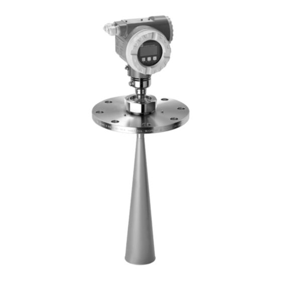
Micropilot S FMR540
Level-Radar
These Instructions are Brief Operating Instructions; they do not
replace the Operating Instructions included in the scope of
supply.
For detailed information, refer to the Operating Instructions and
other documentation on the CD-ROM provided or visit
"www.endress.com/deviceviewer".
Solutions
Services
Advertisement
Table of Contents

Related Manuals for Endress+Hauser Micropilot S FMR540


Summary of Contents for Endress+Hauser Micropilot S FMR540
- Page 1 Products Solutions Services KA01059F/00/EN/13.13 71229238 Brief Operating Instructions Micropilot S FMR540 Level-Radar These Instructions are Brief Operating Instructions; they do not replace the Operating Instructions included in the scope of supply. For detailed information, refer to the Operating Instructions and other documentation on the CD-ROM provided or visit "www.endress.com/deviceviewer".
-
Page 2: Table Of Contents
Table of contents Micropilot S FMR540 4 to 20 mA HART Table of contents 1 Safety instructions ............. 3 1.1 Designated use . -
Page 3: Safety Instructions
Micropilot S FMR540 4 to 20 mA HART Safety instructions Safety instructions Designated use The Micropilot S is a compact radar level transmitter for the continuous, contactless measurement of predominantly solids. The device can also be freely mounted outside closed metal vessels because of its operating frequency in the K-band and a maximum radiated pulsed energy of 1 mW (average power output 1 μW). -
Page 4: Return
Safety instructions Micropilot S FMR540 4 to 20 mA HART CAUTION Changes or modifications not expressly approved by the part responsible for compliance could void the user’s authority to operate the equipment. Return Follow the instructions on returning the device as outlined in the Operating Instructions (BA00326F/00/EN) on the CD-ROM provided. - Page 5 Micropilot S FMR540 4 to 20 mA HART Safety instructions 1.5.3 Tool symbols Symbol Meaning Allen key A0011221 1.5.4 Symbols for certain types of information Symbol Meaning Allowed Indicates procedures, processes or actions that are allowed. A0011182 Forbidden Indicates procedures, processes or actions that are forbidden.
- Page 6 Safety instructions Micropilot S FMR540 4 to 20 mA HART 1.5.6 Symbols at the device Symbol Meaning Safety instructions Observe the safety instructions contained in the associated Operating Instructions. A0019159 Temperature resistance of the connection cables Specifies the minimum value of the temperature resistance of the connection cables.
-
Page 7: Installation Instructions
Micropilot S FMR540 4 to 20 mA HART Installation instructions Installation instructions Quick installation guide ° A0020810 Marker at sensor Marker at flange Incoming acceptance, transport, storage 2.2.1 Incoming acceptance Check the packing and contents for any signs of damage. Check the shipment, make sure nothing is missing and that the scope of supply matches your order. -
Page 8: Installation Instructions
Installation instructions Micropilot S FMR540 4 to 20 mA HART Installation instructions 2.3.1 Mounting kit For the mounting , you will require the following tool: • The tool for flange mounting • 90 mm wrench for adjustment of the alignment device (only for devices with alignment device) •... - Page 9 Micropilot S FMR540 4 to 20 mA HART Installation instructions 2.3.3 Orientation Orientation • Recommended distance (1) wall - outer edge of nozzle: ~1/6 of tank diameter ("Beam angle", ä 9). • Not in the centre (3), interference can cause signal loss.
- Page 10 Installation instructions Micropilot S FMR540 4 to 20 mA HART Horn antenna Antenna size 100 mm (4") Beam angle () 8° Recommended distance to wall Measuring distance Beamwidth diameter (W) 0° tilting 3° tilting 5 m (16 ft) 0,70 m (2.3 ft) 0,89 m (2.9 ft)
- Page 11 Micropilot S FMR540 4 to 20 mA HART Installation instructions 2.3.5 Measuring conditions • The measuring range begins, where the beam hits the tank bottom. Particularly with dish bottoms or conical outlets the level cannot be detected below this point.
- Page 12 Installation instructions Micropilot S FMR540 4 to 20 mA HART Behaviour if measuring range is exceeded The behaviour in case of the measuring range being exceeded can be freely set: The default setting is a current of 22 mA and the generation of a digital warning (E651).
- Page 13 Micropilot S FMR540 4 to 20 mA HART Installation instructions 2.3.7 Standard installation FMR540 with parabolic antenna • Observe installation instructions, ä 8. • Marker is aligned towards tank wall. The marker is located clearly visible on the sensor neck or the flange.
- Page 14 Installation instructions Micropilot S FMR540 4 to 20 mA HART 2.3.8 FMR540 with alignment device Micropilot S should be installed vertically towards the Liquid surface for best measuring performance of ±1 mm (0.04 in). Using the alignment device it is possible to tilt the antenna axis by up to 15°...
- Page 15 Micropilot S FMR540 4 to 20 mA HART Installation instructions 2.3.9 Sensor alignment tool for alignment device A sensor alignment tool (1) is recommended to be used at the time of installation for FMR540 with alignment device. Alignment procedure This procedure is only applicable to the sensors purchased with alignment device (3).
- Page 16 Installation instructions Micropilot S FMR540 4 to 20 mA HART Place the Sensor alignment tool (1) for Micropilot S FMR540. Please, note to avoid any obstacles between the backside of the Alignment tool and the nameplate of Micropilot S FMR540.
- Page 17 Micropilot S FMR540 4 to 20 mA HART Installation instructions 2.3.10 Sealing for custody transfer applications The alignment device can be sealed using the provided slotted capstan screws. The seal wires must be installed against the open direction in order to assure that a loosening of the alignment device is not possible.
-
Page 18: Post-Installation Check
Installation instructions Micropilot S FMR540 4 to 20 mA HART Post-installation check After the measuring device has been installed, perform the following checks: • Is the measuring device damaged (visual check)? • Does the measuring device correspond to the measuring point specifications such as process temperature/pressure, ambient temperature, measuring range, etc.? -
Page 19: Wiring
Micropilot S FMR540 4 to 20 mA HART Wiring Wiring Quick wiring guide When grounding conductive screens, the corresponding directives EN 60079-14 and EN 1127-1 must be observed. Recommendation for safe grounding of conductive screens: CAUTION Before connection please note the following: ‣... - Page 20 Wiring Micropilot S FMR540 4 to 20 mA HART 3.1.1 Wiring CAUTION Before connection please note the following: ‣ The power supply to be delivered by a transmitter supply unit. ‣ Befor removing housing cover at seperate connection compartment turn off the power supply! Insert cable through gland .
- Page 21 Micropilot S FMR540 4 to 20 mA HART Wiring 3.1.2 Wiring with Tank Side Monitor NRF590 CAUTION Before connection please note the following: ‣ Make sure you use the specified cable gland. ‣ Befor removing housing cover at seperate connection compartment turn off the power supply! Insert cable through gland .
-
Page 22: Connecting The Measuring Unit
Wiring Micropilot S FMR540 4 to 20 mA HART Connecting the measuring unit Load HART Minimum load for HART communication: 250 Cable entry Description Feature Option model Thread for cable gland M20 Cable gland M20 Thread for cable gland G ½"... -
Page 23: Equipotential Bonding
– The cable shall be protected e.g. routed in an armoured hose. Power supply • For stand alone operation via two Endress+Hauser RN221N. • Integrated in tank gauging system via Endress+Hauser Tank Side Monitor NRF590 (recommended operation mode). Highly accurate measurements For highly accurate measurements the measured variable must be transmitted using HART protocol to ensure the necessary resolution. -
Page 24: Operation
Operation Micropilot S FMR540 4 to 20 mA HART Operation General structure of the operating menu The operating menu is made up of two levels: • Function groups (00, 01, 03, …, 0C, 0D): The individual operating options of the device are split up roughly into different function groups. -
Page 25: Display And Operating Elements
Micropilot S FMR540 4 to 20 mA HART Operation The third digit numbers the individual functions within the function group: • tank shape • basic setup • medium property • process cond..Hereafter the position is always given in brackets (e.g. "tank shape" (002)) after the described function. - Page 26 Operation Micropilot S FMR540 4 to 20 mA HART 4.2.1 Display Liquid crystal display (LCD) Four lines with 20 characters each. Display contrast adjustable through key combination. ENDRESS + HAUSER – A0020501 Operating keys Bargraph Symbols Function name Parameter Identification number 4.2.2 Display symbols...
- Page 27 Micropilot S FMR540 4 to 20 mA HART Operation 4.2.3 Light emitting diods (LEDs) There is a green and a red LED besides the Liquid crystal display. LED (LED) Meaning red LED continuously on Alarm red LED flashes Warning red LED off...
-
Page 28: Commissioning
Commissioning Micropilot S FMR540 4 to 20 mA HART Commissioning Function check Make sure that all final checks have been completed before you start up your measuring point: • Checklist "Post installation check", ä 18. • Checklist "Post connection check", ä 23. -
Page 29: Overview Basic Setup
Micropilot S FMR540 4 to 20 mA HART Commissioning Overview Basic Setup Tank shape: flat ceiling Measuring cond.: unknown 100% Process cond.: standard Empty calibr. Full calibr. Empty calibr. (=zero); settings in 005 Pipe diameter Distance (distance flange/product); display in 0A5 (only for bypass/stilling well) Safety settings;... - Page 30 Commissioning Micropilot S FMR540 4 to 20 mA HART CAUTION The basic setup is sufficient for successful commissioning in most applications. Complex measuring operations necessitate additional functions that the user can use to customise the Micropilot as necessary to suit his specific requirements. The functions available to do this are described in detail in the BA00341F/00/EN.
-
Page 31: Basic Setup With Device Display Vu331
Micropilot S FMR540 4 to 20 mA HART Commissioning Basic Setup with device display VU331 5.4.1 Function "measured value" (000) On-site display Meaning measured value This function displays the current measured value in the selected unit (see "customer unit" (042)) function). The 63.455 %... - Page 32 Commissioning Micropilot S FMR540 4 to 20 mA HART Function "tank shape" (002), liquids only On-site display Meaning tank shape This function is used to select the tank shape. dome ceiling horizontal cyl bypass Further options: • Dome ceiling •...
- Page 33 Micropilot S FMR540 4 to 20 mA HART Commissioning Function "medium property." (003), liquids only On-site display Meaning medium property This function is used to select the dielectric constant. unknown DC: < 1.9. DC: 1.9...4 Further options: • unknown •...
- Page 34 Commissioning Micropilot S FMR540 4 to 20 mA HART Function "process cond." (004), liquids only On-site display Meaning process cond. This function is used to select the process conditions. standard calm surfaces. turb. surface Further options: • Standard • Calm surface •...
- Page 35 Micropilot S FMR540 4 to 20 mA HART Commissioning Function "empty calibr." (005) On-site display Meaning empty calibr. This function is used to enter the distance from the flange (reference point of the measurement) to the minimum level 5.000 (= zero).
- Page 36 Commissioning Micropilot S FMR540 4 to 20 mA HART Function "pipe diameter" (007) On-site display Meaning pipe diameter This function is used to enter the pipe diameter of the stilling well or bypass pipe. 204.425 inner diameter of bypass/stilling well Microwaves propagate slower in pipes than in free space.
- Page 37 Micropilot S FMR540 4 to 20 mA HART Commissioning Function "check distance" (051) On-site display Meaning check disttance This function triggers the mapping of interference echoes. To do so, the measured distance must be compared with the dist. unknown actual distance to the product surface.
- Page 38 Commissioning Micropilot S FMR540 4 to 20 mA HART dist. too small • At the moment, an interference is being evaluated • Therefore, a mapping is carried out including the presently measured echoes • The range to be suppressed is suggested in the "range of mapping." (052) function dist.
- Page 39 Micropilot S FMR540 4 to 20 mA HART Commissioning Function "start mapping" (053) On-site display Meaning start mapping This function is used to start the interference echo mapping up to the distance given in "range of mapping" (052). off Selection: •...
- Page 40 Commissioning Micropilot S FMR540 4 to 20 mA HART Function "set value" (009) On-site display Meaning set value This function enables the user to offset the difference between the reference level and the measured level 3.000 (or between ullage value and measured distance). To make...
-
Page 41: Envelope Curve With Device Display Vu331
Micropilot S FMR540 4 to 20 mA HART Commissioning On-site display Meaning Return to Group Selection After 3 s, the following message appears Group selection 00 basic setup safety settings linearisation NOTICE After the basic setup, an evaluation of the measurement with the aid of the envelope curve (function group "Envelope curve"... - Page 42 Commissioning Micropilot S FMR540 4 to 20 mA HART 5.5.2 Function "recording curve" (0E2) This function defines whether the envelope curve is read as a • single curve or • cyclic. On-site display recording curve 0 single curve cyclic...
- Page 43 Micropilot S FMR540 4 to 20 mA HART Commissioning 5.5.3 Function "envelope curve display"" (0E3) The envelope curve is displayed in this function. You can use it to obtain the following information: A0021046 Envelope curve only Envelope curve and interference echo suppression (map) Full calibr.
- Page 44 71229238 www.addresses.endress.com...