Table of Contents
Advertisement
Quick Links
Advertisement
Table of Contents

Related Manuals for DURKOPP ADLER 911-210-3020-10

Summary of Contents for DURKOPP ADLER 911-210-3020-10
- Page 1 911-210-10 Operating Instructions...
- Page 2 IMPORTANT READ CAREFULLY BEFORE USE KEEP FOR FUTURE REFERENCE All rights reserved. Property of Dürkopp Adler AG and protected by copyright. Any reuse of these contents, including extracts, is prohibited without the prior written approval of Dürkopp Adler AG. Copyright © Dürkopp Adler AG 2020...
-
Page 3: Table Of Contents
Table of Contents About these instructions ............5 For whom are these instructions intended?........5 Representation conventions – symbols and characters ....5 Other documents ................7 Liability..................7 Safety ................... 9 Basic safety instructions ............... 9 Signal words and symbols used in warnings ......10 Machine description .............. - Page 4 Table of Contents 5.7.3 Updating the bobbin capacity ............. 49 Continuing a seam after an error ..........50 5.8.1 Continuing a seam in Repair mode after an error....... 50 5.8.2 Continuing a seam after thread breaking ........51 Resetting the counter ..............52 5.10 Seam programs and seam sequences ........
- Page 5 Table of Contents 7.4.1 Adjusting the working height for stands with rollers....101 7.4.2 Adjusting the working height for stands without rollers..... 102 Adjusting the pedal ..............103 Assembling the reel stand ............104 Assembling the rear machine cover (911-210-6055-10 only) ............105 Electrical connection..............
- Page 6 Table of Contents Operating Instructions 911-210-10 - 00.0 - 06/2020...
-
Page 7: About These Instructions
About these instructions About these instructions These instructions have been prepared with utmost care. They contain information and notes intended to ensure long-term and reliable operation. Should you notice any discrepancies or if you have improvement requests, then we would be glad to receive your feedback through Customer Service (... - Page 8 About these instructions Steps to be performed when operating the machine (sewing and equipping) Steps to be performed for service, maintenance, and installation Steps to be performed via the software control panel The individual steps are numbered: First step Second step The steps must always be followed in the specified order.
-
Page 9: Other Documents
About these instructions 1.3 Other documents The machine includes components from other manufacturers. Each man- ufacturer has performed a hazard assessment for these purchased parts and confirmed their design compliance with applicable European and na- tional regulations. The proper use of the built-in components is described in the corresponding manufacturer's instructions. - Page 10 About these instructions Operating Instructions 911-210-10 - 00.0 - 06/2020...
-
Page 11: Safety
Safety Safety This chapter contains basic information for your safety. Read the instruc- tions carefully before setting up or operating the machine. Failure to do so can result in serious injury and property damage. 2.1 Basic safety instructions The machine may only be used as described in these instructions. These instructions must be available at the machine's location at all times. -
Page 12: Signal Words And Symbols Used In Warnings
Safety Check the machine during operating for any externally visible damage. Operation Stop working if you notice any changes to the machine. Report any chang- es to your supervisor. Do not use a damaged machine any further. Safety equipment should not be disassembled or deactivated. If it is essen- Safety equipment tial to disassemble or deactivate safety equipment for a repair operation, it... - Page 13 Safety Symbol Type of danger Puncture Crushing Environmental damage Examples of the layout of warnings in the text: Examples DANGER Type and source of danger! Consequences of non-compliance. Measures for avoiding the danger. This is what a warning looks like for a hazard that will result in serious injury or even death if ignored.
- Page 14 Safety CAUTION Type and source of danger! Consequences of non-compliance. Measures for avoiding the danger. This is what a warning looks like for a hazard that could result in environmental damage if ignored. NOTICE Type and source of danger! Consequences of non-compliance.
-
Page 15: Machine Description
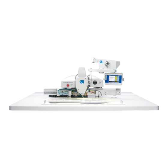
Machine description Machine description 3.1 Components of the machine Fig. 1: Components of the machine ① ② ⑩ ③ ⑨ ④ ⑧ ⑤ ⑥ ⑦ (1) - Machine head (6) - Compressed air maintenance unit (2) - Quick-stop (7) - Pedal (3) - Reel stand (8) - Compressed air gun (4) - Tabletop... -
Page 16: Proper Use
Machine description 3.2 Proper use The machine may only be used with sewing material that satisfies the requirements of the specific application at hand. The machine is intended only for use with dry sewing material. The sewing material must not contain any hard objects. The needle thicknesses permissible for the machine are listed in the Technical data (... -
Page 17: Declaration Of Conformity
Machine description 3.3 Declaration of Conformity The machine complies with European regulations ensuring health, safety, and environmental protection as specified in the declaration of conformity or in the declaration of incorporation. Operating Instructions 911-210-10 - 00.0 - 06/2020... - Page 18 Machine description Operating Instructions 911-210-10 - 00.0 - 06/2020...
-
Page 19: Operation
Operation Operation The operating sequence consists of several different steps. Fault-free operation is necessary in order to achieve a good sewing result. 4.1 Preparing the machine for operation WARNING Risk of injury from moving, cutting and sharp parts! Crushing, cutting and punctures are possible. If possible, make preparations only when the machine is switched off. -
Page 20: Switching On And Off The Machine
Operation 4.2 Switching on and off the machine Fig. 2: Switching on and off the machine ① (1) - Main switch Switching on the machine To switch on the machine: 1. Turn the main switch (1) to the right into the I position. ... -
Page 21: Switching On Quick-Stop
Operation 4.3 Switching on Quick-stop The quick-stop switch (1) can be used to immediately stop all working steps on the machine, e.g. after an operating mistake. Fig. 3: Switching on Quick-stop ① (1) - Quick-stop switch To switch on quick-stop: 1. -
Page 22: Changing The Needle
Operation 4.4 Changing the needle WARNING Risk of injury from sharp and moving parts! Puncture possible. Switch off the machine before you change the needle. Do not reach into the needle tip. NOTICE Property damage may occur! Machine damage possible from incorrect hook side clearance. When switching to a different needle thickness, adjust the distance between needle and hook (... -
Page 23: Switching On Threading Mode
Operation 4.5 Switching on threading mode WARNING Risk of injury from sharp and moving parts! Puncture or crushing possible. Prior to any maintenance or cleaning work, switch off the machine or set the machine to threading mode. When threading mode is active, do not reach into the hook area until this is lit up. -
Page 24: Threading The Needle Thread
Operation 4.6 Threading the needle thread WARNING Risk of injury from sharp and moving parts! Puncture or crushing possible. Switch off the machine before threading the needle thread. Fig. 6: Threading the needle thread ① ⑰ ② ⑯ ③ ⑮ ④... - Page 25 Operation To thread the needle thread: 1. Place the thread reel on the reel stand and guide the needle thread through the hole in the guide on the thread guide. Important The thread guide must be parallel to the reel stand. 2.
-
Page 26: Adjusting The Needle Thread Regulator
Operation 4.7 Adjusting the needle thread regulator The needle thread regulator determines the needle thread quantity to be guided around the hook. The required thread quantity depends on the thickness of the sewing material, the thread strength, and the stitch length. Larger thread quantity for •... -
Page 27: Winding The Hook Thread
Operation 4.8 Winding the hook thread The separate winder allows the hook thread to be wound both during sewing and when the sewing process is stopped. Fig. 8: Winding the hook thread ⑥ ① ⑤ ② ④ ③ (1) - Thread guide plate (4) - Bobbin winder flap (2) - Thread guide channel (5) - Bobbin shaft... -
Page 28: Changing The Bobbin
Operation 9. Press the bobbin winder flap (4) against the bobbin. The winder starts and stops automatically when the configured bobbin filling volume is reached. 4.9 Changing the bobbin WARNING Risk of injury from sharp and moving parts! Puncture or crushing possible. Switch the machine to threading mode before changing the bobbin. - Page 29 Operation Fig. 10: Changing the bobbin (2) ④ ⑤ ⑥ ⑦ ⑧ (4) - Bobbin (7) - Tension spring (5) - Bobbin case retainer (8) - Slot (6) - Guide 3. Swivel up the bobbin case retainer (5). 4. Remove the empty bobbin. 5.
-
Page 30: Thread Tension
Operation 4.10 Thread tension Together with the hook thread tension, the needle thread tension influences the final seam pattern. With thin sewing material, excessive thread tension can lead to undesired ruffing and thread breaking. Proper setting If the tension of needle thread and hook thread is identical, the thread interlace lies in the middle of the sewing material. - Page 31 Operation Adjusting the hook thread tension WARNING Risk of injury from sharp and moving parts! Puncture or crushing possible. Switch off the machine before you adjust the hook thread tension. Fig. 12: Adjusting the hook thread tension ① ② (1) - Tension spring (2) - Adjusting wheel The hook thread tension is generated by the tension spring (1) and adjusted via the adjusting wheel (2).
-
Page 32: Swiveling The Machine Head Up And Down
Operation 4.11 Swiveling the machine head up and down WARNING Risk of injury from moving parts! Crushing possible. When swiveling down the machine head, hold the machine head in place until it has returned to its position. 4.11.1 Swiveling up the machine head Fig. -
Page 33: Swiveling Down The Machine Head
Operation 2. Lift the machine head in the head cover area (1) and swivel up carefully. The latch (3) latches into place. The space under the stand is now accessible. 4.11.2 Swiveling down the machine head NOTICE Property damage may occur! Risk of machine damage from falling machine head. - Page 34 Operation Operating Instructions 911-210-10 - 00.0 - 06/2020...
-
Page 35: Programming
Programming Programming Fig. 15: Programming ① (1) - Control panel OP7000 The control is operated via the control panel OP7000 (1) located on the right next to the machine head. The screen is a touchscreen, i.e. the buttons are displayed on the screen rather than provided as physical buttons. -
Page 36: Structure Of The Software
Programming 5.1 Structure of the software You can create and manage seam programs and sequences via software. During sewing, these programs are called up and processed stitch by stitch. Information Seam program: A seam program consists of a seam contour with parameters defining the individual contour sections. -
Page 37: Starting The Software
Programming Menu items in popup menus Menu item Function Sub-items Sub-items Described on p. 45 Extras Display options: Vollbild ein/aus Full-screen and zoom (Full screen on / off) p. 45 Zoom ein/aus Technician menu: (Zoom on / off) Adjustments, system ... - Page 38 Programming Information Both functions can also be selected later from within the program via the menu items Extras > Service (See chapters Testing the functions of the machine p. 79) and Changing the language ( p. 77).) If you do not press any buttons, the software automatically switches to the start screen after a few seconds.
- Page 39 Programming • Program bar (4) The seam programs of the seam sequence currently open are displayed in this line. The program currently being executed is highlighted in black. You can use the arrow buttons (6) at the right side of the bar to navigate along the bar and display any additional programs that do not fit on the bar.
-
Page 40: General Operation Of The Software
Programming Information You can use the buttons Speed, Thread tension and Stitch length to access the sewing parameters directly ( p. 59). • Button for Repair mode (9) The topmost button at the right side is used for switching the repair mode on and off. -
Page 41: Closing Windows
Programming 5.4.2 Closing windows A number of different buttons can be used for closing the currently open window. Button Meaning At the upper right in the title bar of all windows: The program jumps back by one navigation level. In windows with data entry or selection fields: ... -
Page 42: Scrolling The Display
Programming 5.4.4 Scrolling the display Fig. 21: Scrolling the display ① (1) - Scrollbar A scrollbar (1) is displayed on the right when a displayed image is larger than the screen height. To scroll the display: 1. Drag the scrollbar (1) up or down. 5.4.5 Selecting options from a list When selecting options, a distinction is made between round radio buttons and square check boxes. - Page 43 Programming To select options using radio buttons: 1. Press the desired option. The selected option (1) is marked with a dot. Selection with check boxes Fig. 23: Selection with check boxes ① (1) - Check box: Selected elements Square check boxes allow for the selection of multiple entries. To select options using check boxes: 1.
-
Page 44: Using File Filters
Programming 5.4.6 Using file filters Fig. 24: File filter When opening, copying or deleting seam programs a list of all available files is displayed. You can use the filter functions to make the list more manageable: To use file filters: 1. -
Page 45: Entering Text
Programming 5.4.7 Entering text A text entry window is displayed when text needs to be entered, e.g. for the name of a seam program. Fig. 25: Entering text ① ② ⑤ ④ ③ (1) - Input line (4) - DEL: Delete a character (2) - Keyboard (5) - Aa: Switching between uppercase/ (3) - OK (CR): Adopt the entered text... -
Page 46: Entering Parameter Values
Programming 5.4.8 Entering parameter values A numeric entry window opens when numeric values for program or machine parameters need to be entered. Fig. 26: Entering parameter values ① ② ③ ⑥ ④ ⑤ (1) - Title bar (4) - Value range (2) - Status bar (5) - Input field (3) - Symbol... -
Page 47: Switching The Full-Screen Display On And Off
Programming 5.4.9 Switching the full-screen display on and off In order to see the seam contour in more detail you can switch the main window (1) to occupy the full screen and hide the buttons (2) on the right side of the start screen. Fig. -
Page 48: Opening A Seam Program Or Seam Sequence For Sewing
Programming 5.5 Opening a seam program or seam sequence for sewing To open a seam program or seam sequence for sewing: Datei (File) Öffnen (Open) 1. Press the menu items > The file selection screen is displayed. All existing seam programs and seam sequences are displayed. Information Dateifilter (File Filter) You can use the... -
Page 49: Briefly Sewing With Modified Values
Programming 5.6 Briefly sewing with modified values If you wish to briefly sew with a special material or use a particular thread strength with different values, without changing the seam program, you can use the Korrektur (Correction) menu item to temporarily change the values for thread tension and speed. -
Page 50: Sewing With A Modified Speed
Programming 5.6.2 Sewing with a modified speed To sew with a modified speed: Korrektur (Correction) 1. Press the menu items > Nähdrehzahl (Speed) The window for changing the thread tension appears: Fig. 31: Sewing with a modified speed 2. Enter the desired speed. 3. -
Page 51: Changing The Bobbin
Programming 5.7.1 Changing the bobbin Fig. 32: Changing the bobbin To change the bobbin: 1. Press the Spulenwechsel (Bobbin change) button. 2. Change the bobbin ( p. 48). 3. Use the Vor (Forwards) Zurück (Back) buttons to move to the point where sewing is to continue. 4. -
Page 52: Continuing A Seam After An Error
Programming 5.8 Continuing a seam after an error 5.8.1 Continuing a seam in Repair mode after an error In Repair mode you can move to any desired point on the contour, e.g. in order to continue the seam program from this position after an error has occurred. -
Page 53: Continuing A Seam After Thread Breaking
Programming 5.8.2 Continuing a seam after thread breaking When the machine was set up, the needle thread monitor mode that is supposed to be active was selected in the machine parameters (MP 3 ( p. 73)). In the event of an error, the machine will undo a certain number of preset stitches and stop. -
Page 54: Resetting The Counter
Programming Checking or changing the bobbin To change or check the bobbin: 1. Press the Spulenwechsel (Bobbin change) button. The display shows a prompt asking whether you wish to reset the bobbin counter. 2. Press the JA (YES) button if you wish to change the bobbin. ... -
Page 55: Seam Programs And Seam Sequences
Programming 5.10 Seam programs and seam sequences 5.10.1 Creating a new seam program New seam programs are created using a Teach-In procedure. Individual seam paths with specific sewing parameters are defined via the control panel in order to do this. To create a new seam program: Datei (File) Neu (New) - Page 56 Programming 3. Press the OK (4) button. The desired starting point is adopted and marked with a green / blue dot. Selecting the line type 4. Use the line selection buttons (8) to select the type of line to be defined: •...
- Page 57 Programming Button Meaning Thread tension Stroke height Thread cutting Drawing a path 7. Use the arrow buttons to move the cursor to the end point of the desired path. Information Alternatively, you can press an arrow button once in order to define the direction and then continue moving in this direction by pressing the pedal.
-
Page 58: Performing A Contour Test
Programming Saving a seam program After you have defined all the seam paths, you can save the seam program and specify a name for the program. 1. Press the Speich...(Save...) button. The window for entering the name of the seam program opens. 2. -
Page 59: Editing A Seam Program
Programming Fig. 37: Performing a contour test 2. Move along the contour stitch by stitch using the Vor (Forwards) and Zurück (Back) buttons or the pedal. 3. Check that all points lie within the sewing field. 5.10.3 Editing a seam program You can change the contour and the sewing parameters of existing seam programs. - Page 60 Programming Fig. 38: Changing the contour of a seam program (1) ① ② (1) - Cursor (2) - Scale: First to last stitch 2. Use the arrow buttons to move the cursor (1) to the position on the contour that is to be changed. Information You can also use the slider control on the scale (2) to select the stitching area you wish to change:...
- Page 61 Programming Fig. 40: Changing the contour of a seam program (3) 6. Select the desired technology operation(s) for the new seam path ( p. 40). 7. Confirm the selection with OK. You are returned to the detail window with the modified contour. 8.
- Page 62 Programming Fig. 41: Changing seam program parameters 2. Press the desired parameter group. The individual parameters of this group are displayed. 3. Press the desired parameter. The window for modifying the parameter value opens. 4. Set the parameter to the desired value ( p. 44). Operating Instructions 911-210-10 - 00.0 - 06/2020...
- Page 63 Programming There are 8 program parameter groups: Symbol Parameter group PP1 - Configuration General settings PP2 - Load mode Load mode and position PP3 - Deposit mode Deposit mode and position PP4 - Soft start Number of stitches and speed PP5 - Needle thread monitor Sensitivity value for the needle thread monitor PP6 - Thread consumption...
- Page 64 Programming Symbol Meaning Marking lamps Up to 4 marking lamps for easier alignment of the sewing material can be controlled (the additional equipment must be activated) Reversal mode The following options can be set: • Not activated: The needle remains at the Stop position •...
- Page 65 Programming Symbol Meaning Loading position X The value range varies depending on the subclass and sewing field size. Loading position Y The value range varies depending on the subclass and sewing field size. PP3 - Deposit mode Symbol Meaning Deposit mode The following options can be set: •...
- Page 66 Programming PP4 - Soft start Symbol Meaning Soft-start stitch count (min. = 0.. max. = 10; Def. 5) Soft-start speed (min. = 100 .. max. = 2000; Def. 300 rpm) PP5 - Needle thread monitor (min. = 0 .. max. = 99; Def. 5) Only active if activated in the machine parameters.
-
Page 67: Creating A New Seam Sequence
Programming PP8 - Scaling. Symbol Meaning X scaling (min. = 80… max. = 120; Def. = 100 %) 100% corresponds to the original size. Y scaling (min. = 80… max. = 120; Def. = 100 %) X scaling origin (min. = -150.0… max. = 150.0; Def. = 0.0 mm) Y scaling origin (min. -
Page 68: Editing A Seam Sequence
Programming 2. Press the desired seam program. The selected seam program is highlighted with a dark background. 3. Press the Einfügen (Insert) button. The seam program is transferred to the seam sequence and is displayed in the Sequenz (Sequence) field on the left side of the screen. -
Page 69: Saving A Seam Program Or Seam Sequence Under A Different Name
Programming Fig. 43: Editing a seam sequence 3. Use the buttons Einfügen (Insert) and Löschen (Delete) to add programs to the seam sequence or remove programs from the seam sequence. 5.10.6 Saving a seam program or seam sequence under a different name You can also save existing seam programs or seam sequences under a different name. -
Page 70: Copying A Seam Program Or Seam Sequence
Programming 4. Enter the desired name and adopt the change by pressing (CR) ( p. 43). The seam program or seam sequence is now available under this name for sewing, editing or copying. 5.10.7 Copying a seam program or seam sequence You can also copy seam programs or seam sequences from a USB key to the control or from the control to a USB key. -
Page 71: Deleting A Seam Program Or Seam Sequence
Programming 4. Press the Datei koperen (Copy File) button. The selected file is copied to the USB key or the control. 5.10.8 Deleting a seam program or seam sequence Seam programs or seam sequences that are no longer required can be deleted from the control. -
Page 72: Editing Machine Parameters
Programming 5.11 Editing machine parameters You use the machine parameters to define the basic machine settings. These basic settings apply to all programs. To edit the machine parameters: 1. Press the menu items Bearbeiten (Edit) > Maschinen- parameter (Machine parameters) ... - Page 73 Programming Overview of the individual machine parameters MP1 - Configuration Symbol Meaning Needle cooling The following options can be set: • Without: No needle cooler activated. • Air cooling (Def.): The needle is cooled with air while sewing the seam •...
- Page 74 Programming Symbol Meaning Pedal mode The following options are available: • Mode 1: The current position of the pedal is evaluated • Mode 2 (Def.): The pedal must be returned to the initial position after every actuation before a new actuation is recognized •...
- Page 75 Programming MP2 - Limit values Symbol Meaning Max. speed (min. = 500 .. max. = 2700; Def. 2700 rpm) All sewing programs are limited to this maximum speed Max. run-empty speed (min. = 10 .. max. = 100; Def. 100 %) Limits all clamp movements between the seams to this value Feed starting angle (min.
- Page 76 Programming Symbol Meaning Position of bobbin change X The value range varies depending on the subclass and sewing field size Position of bobbin change Y The value range varies depending on the subclass and sewing field size MP4 - Thread cutting Symbol Meaning Cutting speed...
- Page 77 Programming MP6 - Counters Symbol Meaning Counter type The following options are available: • Increment counter (Def.): The counter is incremented after each sewn program • Decrement counter: The counter is decremented after each sewn program • Increment seam sequence counter: The counter is incremented after each seam sequence sewn •...
-
Page 78: Checking And Changing The Technical Settings
Programming 5.12 Checking and changing the technical settings The technical settings are made via the menu item Extras > Service Fig. 49: Checking and changing the technical settings Important A password must always be entered in order to access the additional Extras Service menu items in... -
Page 79: Changing The Language
Programming Defining the password protected areas To define the password protected areas: Extras Service Einstellungen 1. Press the menu items > > (Settings) The Einstellungen (Settings) window appears. Operator Passwort (Password) 2. Press the option. In the next window the Aktivieren/De-aktivieren (Activate/Deactivate) option indicates the type of... -
Page 80: Setting The Brightness
Programming 5.12.4 Setting the brightness To set the brightness: Extras Service Einstellungen 1. In the menu item > > (Settings) Bedienfeld-Einstellungen press the (Control panel settings) option. Kontrast (Contrast) 2. In the following window press the Helligkeit (Brightness) option. A window with slider controls is displayed. 3. -
Page 81: Testing The Functions Of The Machine
Programming 5.13 Testing the functions of the machine You can use the Extras > Service > Multitest (Multi test) menu item to check the inputs and outputs, test the sewing motor and set the stroke position. Fig. 50: Testing the functions of the machine Information Transportklammer (Transport clamp) function... - Page 82 Programming Fig. 51: Testing inputs and outputs ① ② (1) - Area for input elements (2) - Area for output elements The input elements are listed and selected at the left side (1) and the output elements at the right side (2). ausgewählt: (selected:) 2.
-
Page 83: Adjusting The Stroke Position
Programming Output elements Meaning Foot mode Hook cover Needle cooling on Right clamp Left clamp Stitch position optimization Threading switch lamp on Oil level indicator warning light on Marking lamp 1 (Z) Marking lamp 2 (Z) Marking lamp 3 (Z) Marking lamp 4 (Z) 5.13.2 Adjusting the stroke position WARNING... -
Page 84: Testing The Sewing Motor
Programming Symbol Meaning Go to position Adjust the sewing foot height Switch off the power to the drives Manually check the freedom of motion of the sewing foot rod 2. Press the desired symbol and execute the function. 5.13.3 Testing the sewing motor WARNING Risk of injury from sharp and moving parts! Puncture or crushing possible. -
Page 85: Calling Up Log Displays And Error Lists
Programming 3. Enter the desired value (300 - 2000 rpm). 4. Press the button. The window for entering the cutting speed opens. 5. Enter the desired value (70 - 500 rpm). 6. Press the button. The sewing motor runs at the entered speed. 7. -
Page 86: Initializing The Control And Performing Updates
Programming Symbol Meaning Control unit events List of the latest errors Log configuration Only for Dürkopp Adler Service personnel Log display List of the last log settings State of control panel Status appears in the log display 5.14 Initializing the control and performing updates Extras Service Initialisierung... -
Page 87: Initializing The Control
Programming 5.14.1 Initializing the control Important Initializing the control resets all values to the factory default settings. All changes are lost. Only execute this option if you really want to return to the factory settings. Order Save your seam programs and seam sequences to a USB key before performing initialization. -
Page 88: Cad Professional
Programming Fig. 55: Performing an update of the control ① (1) - USB port 3. Switch on the machine. The software update is performed automatically. Information If the automatic update does not function then you can use the menu items Extras Service Initialisierung (Initialize) -
Page 89: Maintenance
Maintenance Maintenance WARNING Risk of injury from sharp parts! Punctures and cutting possible. Prior to any maintenance work, switch off the machine or set the machine to threading mode. WARNING Risk of injury from moving parts! Crushing possible. Prior to any maintenance work, switch off the machine or set the machine to threading mode. -
Page 90: Cleaning
Maintenance 6.1 Cleaning WARNING Risk of injury from flying particles! Flying particles can enter the eyes, causing injury. Wear safety goggles. Hold the compressed air gun so that the particles do not fly close to people. Make sure no particles fly into the oil pan. NOTICE Property damage from soiling! Sewing dust and thread residues can impair the operation of... -
Page 91: Cleaning The Motor Fan Mesh
Maintenance Areas particularly susceptible to soiling: • Knife on the winder (4) • Area under the throat plate (3) • Hook (2) • Area around the needle (1) To clean the machine: 1. Remove any dust and thread residues using a compressed air gun or a brush. -
Page 92: Lubricating
Maintenance 6.2 Lubricating CAUTION Risk of injury from contact with oil! Oil can cause a rash if it comes into contact with skin. Avoid skin contact with oil. If oil has come into contact with your skin, wash the affected areas thoroughly. NOTICE Property damage from incorrect oil! Incorrect oil types can result in damage to the machine. -
Page 93: Lubricating The Machine Head
Maintenance 6.2.1 Lubricating the machine head Proper setting The oil level is between the minimum level marking and the maximum level marking. Fig. 58: Lubricating the machine head ① ② ③ (1) - Refill opening (3) - Minimum level marking (2) - Maximum level marking To lubricate the machine head: 1. -
Page 94: Lubricating The Hook
Maintenance 6.2.2 Lubricating the hook The approved oil quantity for hook lubrication is a factory specification. Proper setting 1. Hold a piece of blotting paper next to the hook (1) while sewing. After sewing a stretch of approx. 1 m, the blotting paper will have been sprayed with a thin and even film of oil. -
Page 95: Servicing The Pneumatic System
Maintenance 6.3 Servicing the pneumatic system 6.3.1 Adjusting the operating pressure NOTICE Property damage from incorrect adjustment! Incorrect operating pressure can result in damage to the machine. Ensure that the machine is only used when the operating pressure is set correctly. Proper setting Refer to the Technical Data (... -
Page 96: Draining The Water-Oil Mixture
Maintenance 6.3.2 Draining the water-oil mixture NOTICE Property damage from excess liquid! Too much liquid can result in damage to the machine. Drain liquid as required. The collection tray (2) of the pressure regulator will show accumulation of a water-oil mixture. Proper setting The water-oil mixture must not rise up to the level of the filter element (1). -
Page 97: Cleaning The Filter Element
Maintenance 6.3.3 Cleaning the filter element NOTICE Damage to the paintwork from solvent-based cleaners! Solvent-based cleaners damage the filter. Use only solvent-free substances for washing out the filter tray. Fig. 62: Cleaning the filter element ① ② ③ (1) - Filter element (3) - Drain screw (2) - Collection tray To clean the filter element:... -
Page 98: Servicing Specific Components
Maintenance 6.4 Servicing specific components Checking the toothed belt WARNING Risk of injury from moving parts! Crushing possible. Switch off the machine before checking the condition of the toothed belt. The condition of the toothed belt must be checked once a month. Important A damaged toothed belt must be replaced immediately. -
Page 99: Setup
Setup Setup WARNING Risk of injury from cutting parts! Cutting injuries may be sustained while unpacking and setting up the machine. Only qualified specialists may set up the machine. Wear safety gloves. WARNING Risk of injury from moving parts! Crushing injuries may be sustained while unpacking and setting up the machine. -
Page 100: Transporting The Machine
Setup 7.2 Transporting the machine WARNING Risk of injury from moving parts! Crushing possible. The machine is heavy. ALWAYS use a lifting carriage or stacker for lifting the machine to avoid back injuries or crushing injuries if the machine falls down. WARNING Risk of injury from unsafe positioning of the machine! - Page 101 Setup Fig. 63: Transporting the machine ① ② (1) - Nut (2) - Stand foot To transport a machine with rollers: 1. Loosen the nuts (1). 2. Rotate the stand feet (2) fully upwards. 3. Tighten the nuts (1) so that the stand feet (2) remain upwards. 4.
-
Page 102: Removing The Transport Locks
Setup 7.3 Removing the transport locks The transport locks protect the machine during movement and must be removed prior to setup. 1. Remove all transport locks before setting up the machine. Important NOTICE Property damage may occur! Damage to the machine during transport. NEVER transport the machine without the transport locks. -
Page 103: Adjusting The Working Height For Stands With Rollers
Setup 7.4.1 Adjusting the working height for stands with rollers The working height is continuously adjustable between 800 and 1050 mm (clearance between the floor and upper edge of the tabletop). Fig. 64: Adjusting the working height for stands with rollers ①... -
Page 104: Adjusting The Working Height For Stands Without Rollers
Setup 7.4.2 Adjusting the working height for stands without rollers The working height is continuously adjustable between 760 and 910 mm (clearance between the floor and upper edge of the tabletop). Fig. 65: Adjusting the working height for stands without rollers ②... -
Page 105: Adjusting The Pedal
Setup 7.5 Adjusting the pedal The pedal can be freely positioned in front of the machine as far as the cable allows. Fig. 66: Adjusting the pedal ① (1) - Pedal To adjust the pedal: 1. Position the pedal (1) in front of the machine so that pedal and machine can be comfortably operated. -
Page 106: Assembling The Reel Stand
Setup 7.6 Assembling the reel stand Fig. 67: Assembling the reel stand ① ④ ③ ① ② ② ③ (1) - Reel stand (3) - Thread reel holder (2) - Nut (4) - Thread guide To assemble the reel stand: 1. -
Page 107: Assembling The Rear Machine Cover (911-210-6055-10 Only)
Setup 7.7 Assembling the rear machine cover (911-210-6055-10 only) Fig. 68: Assembling the rear machine cover (1) ① ① (1) - Screws To assemble the rear machine cover: 1. Loosen the 4 screws (1). Fig. 69: Assembling the rear machine cover (2) ①... -
Page 108: Electrical Connection
Setup Fig. 70: Assembling the rear machine cover (3) ② (2) - Cover 3. Tighten the screws (1). 7.8 Electrical connection DANGER Risk of death from live components! Unprotected contact with electricity can result in serious injuries or death. Only qualified specialists may perform work on electrical equipment. -
Page 109: Pneumatic Connection
Setup 7.9 Pneumatic connection NOTICE Property damage from oily compressed air! Oil particles in the compressed air can cause malfunctions of the machine and soil the sewing material. Ensure that no oil particles enter the compressed air supply. NOTICE Property damage from incorrect adjustment! Incorrect system pressure can result in damage to the machine. -
Page 110: Adjusting The Operating Pressure
Setup 7.9.2 Adjusting the operating pressure NOTICE Property damage from incorrect operating pressure! Incorrect operating pressure can result in damage to the machine. Ensure that the machine is only used when the operating pressure is set correctly. Proper setting Refer to the Technical Data ( p. 123) chapter for the permissible operating pressure. -
Page 111: Performing A Test Run
Setup 7.10 Performing a test run When setup is complete, perform a test run to check the functionality of the machine. To perform a sewing test: 1. Switch off the machine. 2. Thread the needle thread ( p. 22). 3. Insert the bobbin ( p. 26). 4. - Page 112 Setup Operating Instructions 911-210-10 - 00.0 - 06/2020...
-
Page 113: Decommissioning
Decommissioning Decommissioning WARNING Risk of injury from a lack of care! Serious injuries may occur. ONLY clean the machine when it is switched off. Allow ONLY trained personnel to disconnect the machine. CAUTION Risk of injury from contact with oil! Oil can cause a rash if it comes into contact with skin. - Page 114 Decommissioning Operating Instructions 911-210-10 - 00.0 - 06/2020...
-
Page 115: Disposal
Disposal Disposal CAUTION Risk of environmental damage from improper disposal! Improper disposal of the machine can result in serious environmental damage. ALWAYS comply with the national regulations regarding disposal. The machine must not be disposed of in the normal household waste. The machine must be disposed of in a suitable manner in accordance with all applicable national regulations. - Page 116 Disposal Operating Instructions 911-210-10 - 00.0 - 06/2020...
-
Page 117: Troubleshooting
Troubleshooting 10 Troubleshooting 10.1 Customer Service Contact for repairs and issues with the machine: Dürkopp Adler AG Potsdamer Str. 190 33719 Bielefeld, Germany Tel. +49 (0) 180 5 383 756 Fax +49 (0) 521 925 2594 Email: service@duerkopp-adler.com Internet: www.duerkopp-adler.com 10.2 Messages of the software Code Description... - Page 118 Troubleshooting Code Description Troubleshooting 1058 Sewing motor speed 1302 • Sewing motor defective • Replace sewing motor 1342 Sewing motor error • Check the cable from the pulse Control not receiving pulses from encoder in the motor to the control 1344 pulse encoder in motor •...
- Page 119 Troubleshooting Code Description Troubleshooting 2255 Y-axis stepper motor overload • Eliminate sluggishness • Feed system not moving freely • Remove obstacles/adjust the motion • Obstacles to the feed motion 2256 Y-axis stepper motor overtemperature • Feed system not moving freely •...
- Page 120 Troubleshooting Code Description Troubleshooting 3123 Oil sensor active Top off the oil 3210 Thread broken Re-thread the thread 3215 Bobbin empty (remaining thread Insert full bobbin counter) 3220 Bobbin empty (remaining thread Insert full bobbin counter) 3500 Error in calculating the contour data •...
- Page 121 Troubleshooting Code Description Troubleshooting 8351 Test pins error • Switch off and on the machine • Software update • Notify DA Service 8400 Control panel has no valid program Load the current program into the for the DAC. control panel from a USB key. 8401 Control panel has no valid program Load the current program into the...
-
Page 122: Errors In Sewing Process
Troubleshooting 10.3 Errors in sewing process Error Possible causes Remedial action Unthreading at seam Needle thread tension is Check needle thread tension beginning too firm Thread breaking Needle thread and hook Check threading path thread have not been threaded correctly Needle is bent or sharp- Replace needle edged... - Page 123 Troubleshooting Error Possible causes Remedial action Loose stitches Thread tensions are not Check thread tensions adjusted to the sewing material, the sewing material thickness or the thread used Needle thread and hook Check threading path thread have not been threaded correctly Needle breakage Needle thickness is Use recommended needle...
- Page 124 Troubleshooting Operating Instructions 911-210-10 - 00.0 - 06/2020...
-
Page 125: Technical Data
Technical data 11 Technical data 11.1 Data and characteristic values Technical data Unit Type of stitches Hook type Vertical hook Number of needles Needle system 134/35 Needle strength [Nm] 80 - 180 Thread strength [Nm] Needle thread 10/3 Hook thread 20/3 Stitch length [mm] up to 12.7, dependent on seam pattern... -
Page 126: Requirements For Fault-Free Operation
Technical data 11.2 Requirements for fault-free operation Compressed air quality must conform to ISO 8573-1: 2010 [7:4:4]. Operating Instructions 911-210-10 - 00.0 - 06/2020... - Page 128 DÜRKOPP ADLER AG Potsdamer Str. 190 33719 Bielefeld Germany Phone: +49 (0) 521 925 00 Email: service@duerkopp-adler.com www.duerkopp-adler.com...