Table of Contents
Advertisement
Quick Links
Advertisement
Table of Contents

Related Manuals for EverFocus EPTZ3150


Summary of Contents for EverFocus EPTZ3150
- Page 1 Speed Dome EPTZ Series USER MANUAL Date: Dec. 2009...
-
Page 2: Table Of Contents
1. EPTZ SERIES OVERVIEW ...7 1.1. Introduction ...7 1.2. Specifications (3600 series) ...8 1.3. Specifications (3100 series) ...10 1.4. Feature ...12 1.4.1. Profile of EPTZ...12 1.4.2. EPTZ Base Board ...13 1.5. EPTZ Quick Operation Guide (Work with EKB500) ...15 2. EPTZ INSTALLATION...16 2.1. - Page 3 2.5.4. Indoor Concrete Ceiling Mount Adapter ...40 3. EPTZ3600 SERIES CAMERA SETUP MENU ...41 3.1. Structure of the Setup Menu ...41 3.2. VIDEO SETTINGS ...42 3.2.1. EXPOSURE ...42 3.2.2. FOCUS MODE ...44 3.2.3. DIGITAL ZOOM...44 3.2.4. WHITE BALANCE ...44 3.2.5. BACKLIGHT...45 3.2.6.
- Page 4 3.5.5. AUTO RESUME ...67 3.5.6. RESUME TO ...67 3.5.7. POWER UP FUNC...68 3.5.8. AUTO FLIP...68 3.5.9. EXIT ...69 3.6. ALARM ...69 3.6.1. ALARM INPUTS...69 3.6.2. ALARM OUTPUTS...71 3.6.3. MOTION DETECT...72 3.6.4. EXIT ...74 3.7. PRIVATE ZONES ...74 3.8. SYSTEM...77 3.9. INFO...78 3.10.
- Page 5 4.4. OSD/AREAS ...90 4.4.1. CAM. TITLE...90 4.4.2. AREAS ...90 4.4.3. DIRECTIONS ...92 4.4.4. DISPLAY ...93 4.4.5. EXIT ...95 4.5. AUTO MODES ...95 4.5.1. AUTO TRACKING (For Auto Tracking Model Only) ...95 4.5.2. AUTOPAN ...102 4.5.3. PRESET TOURS ...104 4.5.4. PATTERN ...105 4.5.5.
- Page 6 5.1. Manual Control Mode ... 118 5.2. Auto Tracking Mode (For Auto Tracking Models Only) ... 118 5.3. Auto Pan Mode ... 118 5.4. Position Setting ... 119 5.5. Tour Mode ...121 5.6. Alarm Link to a Position/Tour...122 5.7. Other Operations...122...
-
Page 7: Eptz Series Overview
IP66 Available in different models: Models Outdoor (without auto tracking) EPTZ3600 Indoor (without auto tracking) Outdoor (with auto tracking) Indoor (with auto tracking) 180° 36x Optical Zoom Lens EPTZ3600I EPTZ3650 EPTZ3650I 30x Optical Zoom Lens EPTZ3100 EPTZ3100I EPTZ3150 EPTZ3150I... -
Page 8: Specifications (3600 Series)
1.2. Specifications (3600 series) Product Model Pickup Device Video Format Scanning System Picture Elements Horizontal Resolution Sensitivity S/N Ratio Electronic Shutter Digital Slow Shutter Shutter Selection Lens Type Zoom Ratio True Day & Night Backlight Comp. Wide Dynamic Range White Balance Motion Detection Privacy Zone Masking Gamma Correction... - Page 9 Horizontal Rotation Speed Horizontal Rotation Range Tilt Rotation Range Auto Zoom Speed Control Auto Pan, 2 points scanning Auto Pan Speed Dwell Time (2 points) Preset Positions Running to position speed Dwell time at preset position Tour Tour point per group Pattern Position Accuracy Alarm...
-
Page 10: Specifications (3100 Series)
1.3. Specifications (3100 series) Product Model Pickup Device Video Format Scanning System Picture Elements Horizontal Resolution Sensitivity S/N Ratio Electronic Shutter Digital Slow Shutter Shutter Selection Lens Type Zoom Ratio True Day & Night Backlight Comp. Wide Dynamic Range White Balance Motion Detection Privacy Zone Masking Video Output... - Page 11 4 patterns with 90 sec long each Fan auto starts 4 in 2 out with tour/position auto triggering Yes (only for EPTZ3150) 1200/2400/4800/9600bps EVF-1; EVF-2; Pelco-P ;Pelco-D; A-Type; Plus-D; AUTO; (Plus-D supports all other brands, it is equivalent to Pelco-D) Yes (through DIP switch) Pan: 0.01º...
-
Page 12: Feature
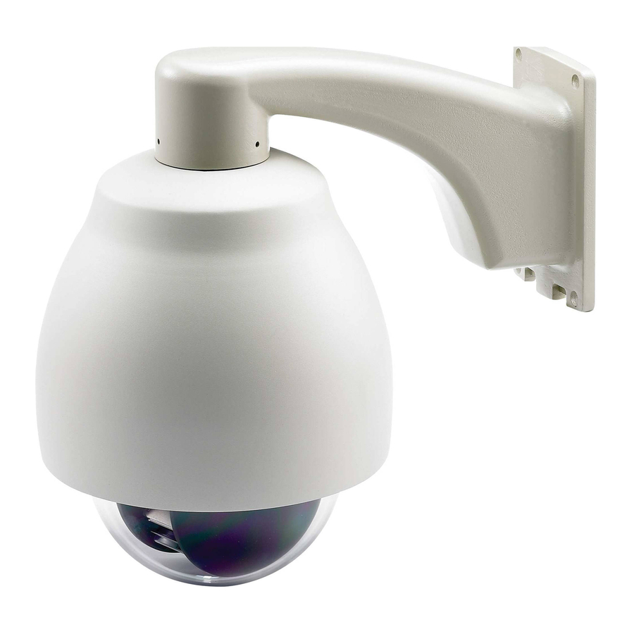
1.4. Feature 1.4.1. Profile of EPTZ Top housing Outer housing Camera main body Camera module Top housing Camera main body Camera Module Outdoor model Wall Mount Bracket Indoor model Sun shield (optional) Bubble Outer housing Bubble... -
Page 13: Eptz Base Board
1.4.2. EPTZ Base Board The base board that is inside the top housing connects to power cable, video cable, control cable, alarm cable and fan. The housing must be removed in order to properly connect the cables. The connectors of cable names are marked on the board in white text. The details of the alarm connector are shown on the APPENDIX. - Page 14 Pin # ALM_NO_B (Alarm Output Normal Open B) ALM_COM_B (Alarm Output Common B) ALM_NC_B (Alarm Output Normal Close B) ALM_NO_A (Alarm Output Normal Open A) ALM_COM_A (Alarm Output Common A) ALM_NC_A (Alarm Output Normal Close A) ALMIN1 (Alarm Input 1) ALMIN2 (Alarm Input 2) ALMIN3 (Alarm Input 3) ALMIN4 (Alarm Input 4)
-
Page 15: Eptz Quick Operation Guide (Work With Ekb500)
1.5. EPTZ Quick Operation Guide (Work with EKB500) EPTZ and EKB500 (Keyboard) can work together by using factory default setting. You just need to connect cables by the following steps: 1. Connect the RS-485 cable to EPTZ and a keyboard (EKB500). 2. -
Page 16: Eptz Installation
2. EPTZ INSTALLATION 2.1. Packing List There are 3 boxes that are camera main body with a camera module, top housing with a base board & pin connector and outer housing with bubble, plus one tool packet in the package. The detail accessories are listed below: Standard Camera Main Body x 1 Top Housing x1... - Page 17 * Wall Mount Bracket * EKB500 (Keyboard) * Indoor Concrete Ceiling Mount Adapter * EKB200 (USB Controller Keyboard)
-
Page 18: Connections
2.2. Connections Power Cable An adapter with 24VAC/3.5A output provides the power to the EPTZ. An extension power line may be needed. Note: Different regions may use different ranges for AC voltage. Be sure to check the voltage range in your area before installing. Video Cable A BNC cable is used for connecting an EPTZ to a DVR or a monitor. -
Page 19: Address Setting
(such as a keyboard or DVR). Notice: Please make sure the power is off while making changes. EPTZ must be restarted before new values will take effect. 2.3.1. Address Setting The address code of the EPTZ should be set to correspond properly with a control device to control multiple dome cameras. - Page 20 Note: You will see the label of Protocol & Baud Rate as well as RS-485 ID address show on the speed dome. For example: for EVF protocol, white keys are all switched downward; for ID Address 0, white keys are all switched downward.
- Page 21 Switch Address Switch Switch Switch Address Address Address Switch Switch Switch Switch Address Address Address Address Switch Switch Switch Switch Switch Address Address Address Address Address...
- Page 22 Switch Address Switch Switch Switch Address Address Address Switch Switch Switch Switch Address Address Address Address Switch Switch Switch Switch Switch Address Address Address Address Address...
-
Page 23: Communication Protocol Setting
2.3.2. Communication Protocol Setting The 1 and 3 bits are used to set communication protocol. The factory default protocol is EVF. Notice: If all protocol switches are set to ON, the EPTZ will enter a self-test mode. 2.3.3. Transmission Speed Setting (Baud Rate Setting) The 4 and 5 bits on the PCB board are used to set the Baud Rate. -
Page 24: Bracket And Speed Dome Installation
2.4. Bracket and Speed Dome Installation 2.4.1. Installation Requirements 1. Installation should be handled by a qualified service agent and should comply with all local regulations. Service personnel should expect potential problems such as surface strength, surface material, falling objects, outer breaches, building vibration or other similar conditions. -
Page 25: Eptz Dome Camera Wall Mount Simple Installation
2.4.2. EPTZ Dome Camera Wall Mount Simple Installation 1. Screw the top housing to bracket and secure it using the included hexagon wrench. 2. Put the waterproof silicon pad on top of the bracket base for waterproof purpose. Waterproof silicon pad Bracket base... - Page 26 3. Connect the RS485, video, and power cables through the top hole of the base board. If necessary, connect the alarm cable as well using the bottom hole. 4. Screw in 4 screws for mounting the bracket base. RS485 cable Video cable Power cable Alarm cable...
- Page 27 5. Screw in 4 long screws to fix the bracket to bracket base.
-
Page 28: Eptz Dome Camera Wall Mount Installation
2.4.3. EPTZ Dome Camera Wall Mount Installation Note: Installations on a wall, pole, or ceiling must be able to support at least five times the weight of the full camera assembly (about 16kg). 1. Pull the hole of the base board to open it. Detach the power and RS485 wires first by using a screw driver. - Page 29 2. Apply the adhesive stripe at back of desiccant pack to the inner side of the top housing. Three packs are included in the package. 3. When the desiccant packs are pasted and the alarm and video cables are reconnected, return the base board to its original position.
- Page 30 4. Put the waterproof silicon pad on top of the base board for waterproof purpose. Waterproof silicon pad 5. Connect the RS485, video, and power cables through the top hole of the base board. If necessary, connect the alarm cable as well using the bottom hole. Base board RS485 cable Video cable...
- Page 31 6. Screw in 4 screws for mounting the bracket base. 7. Thread the cable through the bracket.
- Page 32 8. Screw the top housing to bracket by using a hexagon wrench. 9. Screw in 4 long screws to fix the bracket to bracket base.
- Page 33 10. Pull the hole of base board to open it again. Connect the power and RS485 wires back to power pin and RS485 pin. If you need to connect alarm, connect alarm cable to alarm pin. 11. Hold and push the main body toward the bracket until it is firmly fixed to the bracket. To release it, press orange buttons at both sides of the body.
- Page 34 Note 1: When you push the orange buttons to detach the main body from bracket, please hold the main body carefully, otherwise it may fall down. Note 2: Aim the Arrow label of the main body to the same Arrow label of the bracket when you need to push the main body toward bracket.
-
Page 35: Eptz Dome Camera Ceiling Mount Installation
Note 1: In order to protect the bubble from dirt and scrape, please put on the gloves before installing the bubble. Note 2: The camera module on the mechanical part is very sensitive. Please be careful when installing this part. 13. - Page 36 2. Screw the 3 screws of EPTZ top housing to the 3 holes of indoor recessed mount bracket. 3. Put the indoor recessed mount bracket to the hole that you just made on ceiling. 4. Use a screwdriver to turn the rotation clips (x 3) until they firmly fix to the ceiling. rotation clip →...
- Page 37 5. Snap main body to the indoor recessed mount bracket. NOTE: Aim the Arrow label of the main body to the same Arrow label of the bracket when you need to push the main body toward bracket. 6. Turn the housing of speed dome until it fixes to the top housing.
- Page 38 7. Aim bracket’s fillister to surface ring’s fillister, turn it until it is firmly fixed.
-
Page 39: Bracket & Adapter
2.5. Bracket & Adapter 2.5.1. Indoor Ceiling Pendent Mount Bracket The indoor ceiling pendent mount bracket is used for installing a speed dome on the ceiling. 2.5.2. Pole Mount Adapter The pole adapter is used for installing a wall mount bracket to a pole indoors or outdoors. -
Page 40: Corner Mount Adapter
2.5.3. Corner Mount Adapter The corner mount is used for installing a wall mount bracket to a 270° corner of walls indoors or outdoors. 2.5.4. Indoor Concrete Ceiling Mount Adapter Indoor Concrete Ceiling Mount Adapter is used for indoor installation to concrete ceiling. -
Page 41: Eptz3600 Series Camera Setup Menu
3. EPTZ3600 SERIES CAMERA SETUP MENU This section will show how to navigate and set up the menu of the EPTZ3600/3600I. There are 9 items of the setting menu. NOTE: The controls described in this section are based on using the EKB500 keyboard. 3.1. -
Page 42: Video Settings
3.2. VIDEO SETTINGS In main menu, turn joystick Up / Down to select VIDEO SETTINGS. Turn joystick Left / Right to enter VIDEO SETTINGS sub-menu (see diagram 3.2). VIDEO SETTINGS POSITIONS OSD/AREAS AUTO MODES ALARM PRIVATE ZONES SYSTEM INFO EXIT 3.2.1. - Page 43 EL.SHUTTER: Select electronic shutter mode from the options of the menu. There are AUTO, A.FLK , 1/60, 1/180 , 1/250 , 1/1000 , 1/3000 and 1/10000 at NTSC model; and AUTO, A.FLK, 1/50, 1/150, 1/215, 1/1000, 1/2500 and 1/10000 at PAL model. AUTO: Auto electrical shutter A.FLK: Anti-Flicker.
-
Page 44: Focus Mode
cursor between 0~6) EXIT: Select Exit to save settings and exit from current page. 3.2.2. FOCUS MODE In Focus mode, we define focus type from ONE PUSH, AUTO and Manual. ONE PUSH: Enable the one push trigger focus mode. The focus lens holds the same position until the next trigger command is received. -
Page 45: Backlight
3.2.5. BACKLIGHT This is the function of Back Light Compensation. When the background of subject is too bright, or when the subject is too dark due to shooting in AE mode, back light compensation will make the subject appear clearer. ON: Enable Back Light Compensation. -
Page 46: Negative
3.2.8. NEGATIVE In Negative mode, it will switch ON/OFF the negative art image output. Select from ON and OFF. ON: Enable Negative function OFF: Disable Negative function 3.2.9. WIDE DYNAMIC RANGE In Wide Dynamic Range, we define wide dynamic range from ON and OFF. This function is effective when shooting images against the sun or any other bright light source. -
Page 47: Positions
3.3. POSITIONS In main menu, turn joystick Up or Down to select POSITION option. Press Enter key or turn joystick Left / Right to enter POSITION sub-menu (See diagram 3.4). VIDEO SETTINGS POSITIONS OSD/AREAS AUTO MODES ALARM PRIVATE ZONES SYSTEM INFO EXIT Press Enter key of keyboard to enter SET POSITIONS sub-menu. - Page 48 PRESET NO. 1 POSITION <┘ SPEED DWELL TIME (S) FOCUS MODE MANUAL WHITE BALANCE AUTO TITLE DEFAULT RETURN POSITION: Select from SET and CLEAR. SET: Select SET and press Enter key of keyboard, you will be entered to a sub-menu. Turn the joystick to your desired position.
- Page 49 SPEED: Select the speed for the preset position. The value is from 1 to 255 and 255 is the highest speed. DWELL TIME (S): Select the dwell time (in second) for the preset position from 1 to 99. FOCUS MODE: Select focus mode for the preset position from MANUAL, ONE PUSH and AUTO.
-
Page 50: Osd/Areas
3.4. OSD/AREAS In main menu, turn joystick Up or Down to select OSD/AREAS. Turn joystick Left or Right to enter OSD/AREAS sub-menu (see diagram 3.8) VIDEO SETTINGS POSITIONS OSD/AREAS AUTO MODES ALARM PRIVATE ZONES SYSTEM INFO EXIT 3.4.1. CAM. TITLE Enter the title name for the camera, up to a maximum of 10 characters. - Page 51 In zone menu, you can set a zone and name it, when the speed dome turns to the zone you set, it will display zone name on the screen (only if “OSD/AREAS->Display -> Zone” is set as “YES”). Tilt the joystick up and down to scroll through the characters, then tilt left or right to move to the previous/next position.
-
Page 52: Directions
Tilt the joystick right or left to highlight the current zone or tilt up/down to select a different zone. If you wish to clear the zone you have set, go to “CLR” and press Enter key. 3.4.3. DIRECTIONS Press Enter key of keyboard or turn joystick Left/Right to enter DIRECTIONS sub-menu (see diagram 3.12) CAM. -
Page 53: Display
4. Go to “DEFAULT NORTH” and press Enter key to set the north position as default north position. 5. Go to Return and turn joystick Left/Right to return to previous menu. 3.4.4. DISPLAY Press Enter key of keyboard or turn joystick Left/Right to enter DISPLAY sub-menu (see diagram 3.14) CAM. - Page 54 NO: do not show camera title 3. DIRECTIONS YES: show directions NO: do not show directions 4. ZONES YES: show zones NO: do not show zones 5. PRESET TITLE YES: show preset title NO: do not show preset title 6. ZOOM YES: show zoom multiple when zoom in or zoom out.
-
Page 55: Exit
9. CAMERA STATUS YES: shows camera status NO: do not show camera status 10. RETURN Turn joystick Left/Right to return to previous menu 3.4.5. EXIT Select Exit to save settings and exit from current page. 3.5. AUTO MODES In main menu, turn joystick Up/Down to select AUTO MODES. Turn joystick Left/Right to enter AUTO MODES sub-menu (See diagram 3.15) VIDEO SETTINGS POSITIONS... - Page 56 User can also use preset keys to operate auto tracking related functions. Please refer to ”5.2 Auto Tracking Mode”. AUTO TRACKING ON<┘ AUTOPAN <┘ PRESET TOURS <┘ PATTERN <┘ AUTO RESUME RESUME TO POS.1(H) POWER UP FUNC PREV MODE AUTO FLIP EXIT a.
- Page 57 b. PAN/TILT LIMITS ON: Turn joystick Left/Right to switch Limits on or off. When Limits is on, press Enter key to enter AUTO TRACKING LIMIT menu (see diagram 3.18). Turn the joystick Up/Down to select one of the four following functions and press Enter key to enter its setting menu.
- Page 58 UPPER: In MOVE TO UP LIMIT window (see diagram 3.20), turn the joystick to select the position where you wish to set up limit. Press IRIS+ key of keyboard to save setting and return to previous menu. AUTO TRACKING LIMIT 0 –...
- Page 59 CLEAR PAN: select this option and press Enter key to clear pan setting. CLEAR UPPER: select this option and press Enter key to clear upper limit setting. CLEAR LOWER: select this option and press Enter key to clear lower limit setting. RETURN: select this option and press Enter key to save setting and return to previous menu.
- Page 60 MASK1 CLEAR MASK1 <┘ OFF: disable tracking mask function. d. ZOOM MODE: While tracking an object, the system will zoom in to a suitable ratio for closer view. e. SET DURATION Press Enter key to enter SET DURATION menu. DURATION(S): Set tracking duration time in seconds. Lost Mode: User can set tracking mode when the object is lost on screen.
- Page 61 f. ACTIONS MODE Press Enter key to enter ACTION MODE menu. TOUR 1-8: Track an object while running tour 1-8. TOUR 9-16: Track an object while running tour 9-16. AB PAN: Track an object at poison A/B while running AB PAN ALARM INPUT: If this option is ON, when the alarm is triggered, PTZ start tracking the position or tour depending on the reaction set in “Alarm Inputs”.
-
Page 62: Autopan
3.5.2. AUTOPAN Press Enter key of keyboard or turn joystick Left/Right to enter AUTOPAN sub-menu (see diagram 3.25) AUTO TRACKING <┘ AUTOPAN <┘ PRESET TOURS <┘ PATTERN <┘ AUTO RESUME RESUME TO POS.1(H) POWER UP FUNC PREV MODE AUTO FLIP EXIT a. - Page 63 Press Enter key or turn the joystick Left/Right to enter SET LEFT POS. menu. Turn the joystick to the position where you wish to set Left position. Press IRIS+ key of keyboard to save setting and return to previous menu. (see diagram 3.26) AUTOPAN ENDLESS MODE SPEED...
-
Page 64: Preset Tours
h. DEFAULT ON: all settings in AUTOPAN menu will be returned to default values. OFF: the setting in AUTOPAN menu is not default value. i. RETURN Turn joystick Left/Right to return to previous menu 3.5.3. PRESET TOURS Press Enter key or turn the joystick Left/Right to enter PRESET TOURS sub-menu (see diagram 3.28) AUTO TRACKING <┘... -
Page 65: Pattern
default. e. SPEED: Turn the joystick Right after setting dwell time. Turn the joystick Up or Down to select tour speed from 1 ~255 or default. Press Enter key when you finish Tour setting of preset position. PREV PAGE/NEXT PAGE: Turn the joystick Left to go previous page or turn joystick Right to go next page. - Page 66 PATTERN SETUP PATTERN DURATION ACTION PAT1 PAT2 PLAY PAT3 PLAY PAT4 PLAY IRIS+: RETURN d. Turn the joystick to record the tour you wish to set. Press IRIS+ when you finish setting pattern tour. Press IRIS- if you wish to cancel this action. At duration column of PATTERN SETUP menu, you will see the duration time of pattern you set.
-
Page 67: Auto Resume
3.5.5. AUTO RESUME Return to previous mode, if no action for a period. Turn the joystick Left/Right to set AUTO RESUME. Auto Resume is selectable from OFF, After 30 sec, After 1 min, after 5 min, After 10 min, After 30 min and After 60 min. After this period of time, speed dome will resume to the mode you set in “RESUME TO”. -
Page 68: Power Up Func
3.5.7. POWER UP FUNC Turn the joystick Left or Right to select the mode to return to when power failure occurs. It is selectable from PREV MODE, POS.1 (H), TOUR1, PAT.1, AUTOPAN and OFF. (see diagram 3.34) AUTO TRACKING <┘ AUTOPAN <┘... -
Page 69: Exit
3.5.9. EXIT Exit from the current menu. 3.6. ALARM In main menu, turn joystick Up or Down to select ALARM. Turn joystick Left or Right to enter ALARM sub-menu (see diagram 3.36) VIDEO SETTINGS POSITIONS OSD/AREAS AUTO MODES ALARM PRIVATE ZONES SYSTEM INFO EXIT... - Page 70 NIGHT NO: Set camera at night mode with normal open alarm input. When there is event triggered, the camera will be changed to day mode. OFF: Disable alarm input. ALARM INPUTS <┘ ALARM OUTPUTS <┘ MOTION DETECT <┘ EXIT c. REACTION: The action will be taken when alarm is triggered. OFF: No reaction will be taken when alarm is triggered.
-
Page 71: Alarm Outputs
d. DURATION: Duration of alarm input. TIMEOUT: Turn the joystick Left or Right to select on TIMEOUT and press Enter key to select time-out. Time-out is selectable from 1~99. Press Enter key again to confirm selection. LATCHED: Turn the joystick Left or Right to select on LATCHED. The alarm output will not stop until there is any operation on keyboard TRANSPARENT: Turn the joystick Left or Right to select on TRANSPARENT. -
Page 72: Motion Detect
a. OUTPUT NUM: Select Output number from 1~2. b. INPUT1: Select YES to enable Alarm input 1 for the alarm output selected. Select NO to disable Alarm input 1. c. INPUT2: Select YES to enable Alarm input 2 for the alarm output selected. Select NO to disable Alarm input 2. - Page 73 ALARM INPUTS <┘ ALARM OUTPUTS <┘ MOTION DETECT <┘ EXIT a. Turn the joystick Left or Right to select ON for motion detection. A window as below pops up. MOTION DETECT INFO M1: 67 M2: 87 b. Press Enter key to enter Motion Detection Setting. Use the joystick to select motion area.
-
Page 74: Exit
MOTION DETECT SETTING 1 LEFT RIGHT 0----------12 UPPER 0-------8 LOWER 0-------8 RETURN SENSITIVITY: select motion detection sensitivity level from 1~255. INTERVAL TIME (S): select interval time in seconds from 1~255. Speed dome will stop detecting motion during this interval time. 3.6.4. - Page 75 VIDEO SETTINGS POSITIONS OSD/AREAS AUTO MODES ALARM PRIVATE ZONES SYSTEM INFO EXIT a. ON: Turn joystick Left/Right to select ON/OFF. For private zone ON, press Enter key to enter private zone position. b. Turn the joystick and move to position of private zone. Press IRIS+ or IRIS- key to set private zone size.
- Page 76 c. Select the area to be covered first. Turn joystick Left/Right to adjust width of the private zone area. Turn joystick Up or Down to adjust height of the private zone area. Press IRIS- key to set private zone position. Press IRIS+ to save and return to previous menu.
-
Page 77: System
3.8. SYSTEM In main menu, turn joystick Up/Down to select SYSTEM. Turn joystick Left/Right to enter SYSTEM sub-menu (see diagram 3.44) VIDEO SETTINGS POSITIONS OSD/AREAS AUTO MODES ALARM PRIVATE ZONES SYSTEM INFO EXIT a. AUTO INIT: Select auto initiation time from OFF, DAILY, WEEKLY. Speed dome will automatically initiate and return to the previous position by maintaining all the settings you have done. -
Page 78: Info
-PASSWORD ACTIVE: Select YES to activate password mode. Select NO to disable password mode. -ENTER PASSWORD: Enter the password -VERIFY PASSWORD: Enter the password again to confirm your input. Press IRIS+ key to save and return to previous menu. Press IRIS- key to cancel. -SAVE AND RETURN: Turn joystick Left/Right to save the changes and return to previous menu. -
Page 79: Exit
c. BAUDRATE: shows baud rate of this speed dome d. RS-485-ID: shows RS-485 ID of this speed dome e. PRESET-CNT: Preset counter. This counter counts the preset movement, and 1 is counted when the speed dome runs to preset position. f. -
Page 80: Eptz3100 Series Camera Setup Menu
4. EPTZ3100 SERIES CAMERA SETUP MENU This section will show how to navigate and set up the menu of the EPTZ3100/EPTZ3100I. There are 9 items of the setting menu. NOTE: The controls described in this section are based on using the EKB500 keyboard. 4.1. -
Page 81: Video Settings
4.2. VIDEO SETTINGS In main menu, turn joystick Up / Down to select VIDEO SETTINGS. Turn joystick Left / Right to enter VIDEO SETTINGS sub-menu (see diagram 4.2). VIDEO SETTINGS POSITIONS OSD/AREAS AUTO MODES ALARM PRIVATE ZONES SYSTEM INFO EXIT 4.2.1. - Page 82 EL.SHUTTER: Select electronic shutter mode from the options of the menu. There are AUTO, A.FLK , 1/50, 1/160 , 1/250 , 1/1000 , 1/2500, 1/10000, 1/120,000, X2, X4, X6 and X8. AUTO: The AUTO electronic shutter mode is enabled. The shutter speed is controlled automatically according to the brightness of the screen A.FLK: Anti-Flicker.
-
Page 83: Focus Mode
sec for PAL. AUTO X8, AUTO X12, AUTO X16, AUTO X32, AUTO X64, and AUTO X128 work the same as AUTO X4 with different times of shutter speeds. NOTE: If EL. SHUTTER is selected, SLOW SHUTTER will be disabled. IRIS MODE: AUTO mode or MANUAL mode can be selected. MANUAL: The brightness of the image can be adjusted manually. -
Page 84: Digital Zoom
MANUAL: Enable the manual focus mode. 4.2.3. DIGITAL ZOOM Magnification of the digital zoom can be selected among OFF, 2X, 4X and 8X. OFF: Disable the digital zoom function. 4.2.4. WHITE BALANCE The white balance function corrects the abnormal white color into the normal white color under any color temperature lighting. -
Page 85: Dig. Noise Reduce
built-in infrared (IR) cut-filter which can be disengaged from the image path for increased sensitivity in low light environments. Select from AUTO, DAY and NIGHT NIGHT: IR cut filter is always removed (ICR ON). DAY: IR cut filter is always attached (ICR OFF). AUTO: Auto Day/Night mode switch. -
Page 86: Exit
Notice: When the wide dynamic range is ON, some part of the image may appear solarized. This is normal for the wide dynamic range, and is not a camera malfunction. 4.2.8. EXIT Select Exit to save settings and exit from current page. -
Page 87: Positions
4.3. POSITIONS In main menu, turn joystick Up or Down to select POSITION option. Press Enter key or turn joystick Left / Right to enter POSITION sub-menu (see diagram 4.4). VIDEO SETTINGS POSITIONS OSD/AREAS AUTO MODES ALARM PRIVATE ZONES SYSTEM INFO EXIT Press Enter key of keyboard to enter SET POSITIONS sub-menu. - Page 88 PRESET NO. 1 POSITION <┘ SPEED DWELL TIME (S) FOCUS MODE MANUAL WHITE BALANCE AUTO TITLE DEFAULT RETURN POSITION: Select from SET and CLEAR. SET: Select SET and press Enter key of keyboard, you will be entered to a sub-menu. Turn the joystick to your desired position.
- Page 89 SPEED: Select the speed for the preset position. The value is from 1 to 255 and 255 is the highest speed. DWELL TIME (S): Select the dwell time (in second) for the preset position from 1 to 99. FOCUS MODE: Select focus mode for the preset position from MANUAL, ONE PUSH and AUTO.
-
Page 90: Osd/Areas
4.4. OSD/AREAS In main menu, turn joystick Up or Down to select OSD/AREAS. Turn joystick Left or Right to enter OSD/AREAS sub-menu (see diagram 4.8) VIDEO SETTINGS POSITIONS OSD/AREAS AUTO MODES ALARM PRIVATE ZONES SYSTEM INFO EXIT 4.4.1. CAM. TITLE Enter the title name for the camera, up to a maximum of 10 characters. - Page 91 In zone menu, you can set a zone and name it, when the speed dome turns to the zone you set, it will display zone name on the screen (only if “OSD/AREAS->Display -> Zone” is set as “YES”). Tilt the joystick up and down to scroll through the characters, then tilt left or right to move to the previous/next position.
-
Page 92: Directions
Tilt the joystick right or left to highlight the current zone or tilt up/down to select a different zone. If you wish to clear the zone you have set, go to “CLR” and press Enter key. 4.4.3. DIRECTIONS Press Enter key of keyboard or turn joystick Left/Right to enter DIRECTIONS sub-menu (see diagram 4.12) CAM. -
Page 93: Display
4.4.4. DISPLAY Press Enter key of keyboard or turn joystick Left/Right to enter DISPLAY sub-menu (see diagram 4.14) CAM. TITLE EPTZ3100__ AREAS <┘ DIRECTIONS <┘ DISPLAY <┘ EXIT 2. SHOW OSD: ON: show OSD of Camera Title, Directions, Zones, Preset Title, Motion, Zoom, Fan and Camera Status. - Page 94 4. ZONES YES: show zones NO: do not show zones 5. PRESET TITLE YES: show preset title NO: do not show preset title 6. ZOOM YES: show zoom multiple when zoom in or zoom out. NO: do not show zoom multiple. 7.
-
Page 95: Exit
4.4.5. EXIT Select Exit to save settings and exit from current page. 4.5. AUTO MODES In main menu, turn joystick Up/Down to select AUTO MODES. Turn joystick Left/Right to enter AUTO MODES sub-menu (See diagram 4.15) VIDEO SETTINGS POSITIONS OSD/AREAS AUTO MODES ALARM PRIVATE ZONES... - Page 96 AUTO TRACKING ON<┘ AUTOPAN <┘ PRESET TOURS <┘ PATTERN <┘ AUTO RESUME RESUME TO POS.1(H) POWER UP FUNC PREV MODE AUTO FLIP EXIT a. START POINT ON: Turn joystick Left/Right to switch Start Point on or off. When Start Point is on, press Enter key to enter TRACKING START POS.
- Page 97 key to enter AUTO TRACKING LIMIT menu (see diagram 4.18). Turn the joystick Up/Down to select one of the four following functions and press Enter key to enter its setting menu. AUTO TRACKING START POINT PAN/TILT LIMITS <┘ MASK ZONE ZOOM MODE SET DURATION <┘...
- Page 98 to save setting and return to previous menu. AUTO TRACKING LIMIT <┘ 0 – 360 UPPER <┘ 90 degree LOWER <┘ 0 degree CLEAR PAN <┘ CLEAR UPPER <┘ CLEAR LOWER <┘ RETURN LOWER: In MOVE TO DOWN LIMIT window (see diagram 4.21), turn the joystick to select the position where you wish to set down limit.
- Page 99 CLEAR LOWER: select this option and press Enter key to clear lower limit setting. RETURN: select this option and press Enter key to save setting and return to previous menu. c. MASK ZONE ON: press Enter key to enter TRACKING MASK menu. Turn the joystick Up/Down to select a mask number.
- Page 100 OFF: disable tracking mask function. d. ZOOM MODE: While tracking an object, the system will zoom in to a suitable ratio for closer view. e. SET DURATION Press Enter key to enter SET DURATION menu. DURATION(S): Set tracking duration time in seconds. Lost Mode: User can set tracking mode when the object is lost on screen.
- Page 101 f. ACTIONS MODE Press Enter key to enter ACTION MODE menu. TOUR 1-8: Track an object while running tour 1-8. TOUR 9-16: Track an object while running tour 9-16. AB PAN: Track an object at poison A/B while running AB PAN ALARM INPUT: If this option is ON, when the alarm is triggered, PTZ start tracking the position or tour depending on the reaction set in “Alarm Inputs”.
-
Page 102: Autopan
4.5.2. AUTOPAN Press Enter key of keyboard or turn joystick Left/Right to enter AUTOPAN sub-menu (see diagram 4.25) AUTOPAN <┘ PRESET TOURS <┘ PATTERN <┘ AUTO RESUME RESUME TO POS.1(H) POWER UP FUNC PREV MODE AUTO FLIP EXIT a. TRACKING MODE: (For Auto Tracking Models Only) Auto tracking can be set on when Auto-Pan function is working. - Page 103 Select dwell time of the left position from 1~99 seconds. e. DWELL TIME R (S) Select dwell time of the right position from 1~99 seconds f. SET LEFT POS. Press Enter key or turn the joystick Left/Right to enter SET LEFT POS. menu. Turn the joystick to the position where you wish to set Left position.
-
Page 104: Preset Tours
AUTOPAN ENDLESS MODE SPEED DWELL TIME L (S) DWELL TIME R (S) SET LEFT POS. <┘ SET RIGHT POS. <┘ DEFAULT IRIS-: RETURN h. DEFAULT ON: all settings in AUTOPAN menu will be returned to default values. OFF: the setting in AUTOPAN menu is not default value. i. -
Page 105: Pattern
TRACKING MODE (For Auto Tracking Models Only): Auto tracking can be set on when tour function is working. Turn joystick Left/Right to select tracking mode on/off. The system will go back to tour mode when tracking is not working. Tour NO.: Turn the joystick Left/Right to select tour number first PRE: Turn the joystick Left/Right to select preset position. - Page 106 b. Turn the joystick Left or Right to select action mode, either PLAY, SET or CLEAR. c. Select SET and press Enter key of keyboard. PATTERN SETUP PATTERN DURATION ACTION PAT1 PAT2 PLAY PAT3 PLAY PAT4 PLAY IRIS+: RETURN d. Turn the joystick to record the tour you wish to set. Press IRIS+ when you finish setting pattern tour.
-
Page 107: Auto Resume
4.5.5. AUTO RESUME Return to previous mode, if no action for a period. Turn the joystick Left/Right to set AUTO RESUME. Auto Resume is selectable from OFF, After 30 sec, After 1 min, after 5 min, After 10 min, After 30 min and After 60 min. After this period of time, speed dome will resume to the mode you set in “RESUME TO”. -
Page 108: Alarm Inputs
VIDEO SETTINGS POSITIONS OSD/AREAS AUTO MODES ALARM PRIVATE ZONES SYSTEM INFO EXIT 4.6.1. ALARM INPUTS Press Enter key of keyboard to enter ALARM INPUTS sub-menu. (see diagram 4.33) a. Go to INPUT NO. selection and turn the joystick Left/Right to select alarm input number from 1 ~4. - Page 109 ALARM INPUTS <┘ ALARM OUTPUTS <┘ MOTION DETECT <┘ EXIT c. REACTION: The action will be taken when alarm is triggered. OFF: No reaction will be taken when alarm is triggered. POSITION: When the alarm is triggered, speed dome will go to the preset position. Turn the joystick Left or Right to select on Position and press Enter key to select position number.
- Page 110 to select time-out. Time-out is selectable from 1~99. Press Enter key again to confirm selection. LATCHED: Turn the joystick Left or Right to select on LATCHED. The alarm output will not stop until there is any operation on keyboard TRANSPARENT: Turn the joystick Left or Right to select on TRANSPARENT. The alarm output will not stop until the alarm is stopped.
-
Page 111: Alarm Outputs
4.6.2. ALARM OUTPUTS Press Enter key of keyboard to enter ALARM OUTPUTS sub-menu. (see diagram 4.34) ALARM INPUTS <┘ ALARM OUTPUTS <┘ MOTION DETECT <┘ EXIT a. OUTPUT NUM: Select Output number from 1~2. b. INPUT1: Select YES to enable Alarm input 1 for the alarm output selected. Select NO to disable Alarm input 1. -
Page 112: Motion Detect
Select NO to disable this function. i. RETURN: RETURN to the previous menu. 4.6.3. MOTION DETECT Press Enter key of keyboard to enter MOTION DETECT sub-menu. (see diagram 4.35) ALARM INPUTS <┘ ALARM OUTPUTS <┘ MOTION DETECT <┘ EXIT a. Turn the joystick Left or Right to select ON for motion detection. A window as below pops up. -
Page 113: Private Zones
4.7. PRIVATE ZONES In main menu, turn joystick Up/Down to select PRIVATE ZONES masking. Turn joystick Left/Right to enter PRIVATE ZONE sub-menu (see diagram 4.37) VIDEO SETTINGS POSITIONS OSD/AREAS AUTO MODES ALARM PRIVATE ZONES SYSTEM INFO EXIT a. ON: Turn joystick Left/Right to select ON/OFF. For private zone ON, press Enter key to enter private zone position. - Page 114 c. Select the area to be covered first. Turn joystick Left/Right to adjust width of the private zone area. Turn joystick Up or Down to adjust height of the private zone area. Press IRIS- key to set private zone position. Press IRIS+ to save and return to previous menu.
-
Page 115: System
4.8. SYSTEM In main menu, turn joystick Up/Down to select SYSTEM. Turn joystick Left/Right to enter SYSTEM sub-menu (see diagram 4.40) VIDEO SETTINGS POSITIONS OSD/AREAS AUTO MODES ALARM PRIVATE ZONES SYSTEM INFO EXIT a. AUTO INIT: Select auto initiation time from OFF, DAILY, WEEKLY. Speed dome will automatically initiate and return to the previous position by maintaining all the settings you have done. -
Page 116: Info
PASSWORD ACTIVE: Select YES to activate password mode. Select NO to disable password mode. ENTER PASSWORD: Enter the password VERIFY PASSWORD: Enter the password again to confirm your input. Press IRIS+ key to save and return to previous menu. Press IRIS- key to cancel. SAVE AND RETURN: Turn joystick Left/Right to save the changes and return to previous menu. -
Page 117: Exit
c. BAUDRATE: shows baud rate of this speed dome d. RS-485-ID: shows RS-485 ID of this speed dome e. PRESET-CNT: Preset counter. This counter counts the preset movement, and 1 is counted when the speed dome runs to preset position. f. -
Page 118: Eptz Function Setup And Operation
5. EPTZ FUNCTION SETUP AND OPERATION 5.1. Manual Control Mode Manual control: Shift Joystick Up/Down/Left/Right, and turn it Clockwise/Counterclockwise to control speed dome. Use the control keys which are Zoom, Focus and IRIS function keys on the keyboard to Zoom In/Out, focus N (near)/F (Far), or IRIS +/-. Note: Zoom In/Out control keys will be disabled when entering to OSD menu mode. -
Page 119: Position Setting
B clockwise. 360° auto pan: Press Shift + A.Pan to enter the 360° auto pan. Sy stem will ask you to enter 360° auto pan speed (1~239). The camera wi ll turn 360° automatically, but not tilt. 5.4. Position Setting Focus on a preset position: Press the number key, and then press Position to focus on the number of preset position;... - Page 120 94 => Initial 96 => Stop Scan 97 => Start running tour 1 98 => Frame scan (60 degree / step) Default speed is 32. It can be changed by EVF Keyboard (Shift + A.Pan setting speed. Dwell time: default is 2 sec; It can be changed by EVF Keyboard Set + A.Pan setting dwell time of A pos or B pos.
-
Page 121: Tour Mode
5.5. Tour Mode In the tour mode, you can set a tour for viewing. There are 16 tours can be set, and 16 preset positions in a tour. One-way tour Mode: Press Tour to enter the tour mode. The system will ask you to enter the tour number you would like to run, and starts the tour after pressing Enter. -
Page 122: Alarm Link To A Position/Tour
5.6. Alarm Link to a Position/Tour The speed dome has 4 alarm inputs that can be set to link to a position or a tour when an alarm is triggered. Set an alarm link: Press F1 to set an alarm link. Enter the alarm number, and then press Enter. Switch the Joystick up/down to select a position or a tour, enter a position or tour number, and then press Enter to confirm the alarm link setting. - Page 123 EverFocus Electronics Corp. Head Office: 12F, No.79 Sec. 1 Shin-Tai Wu Road, Hsi-Chih, Taipei, Taiwan TEL: +886-2-26982334 FAX: +886-2-26982380 www.everfocus.com.tw USA L.A. Office: 1801 Highland Ave. Unit A Duarte, CA 91010, U.S.A. TEL: +1-626-844-8888 FAX: +1-626-844-8838 www.everfocus.com USA N.Y. Office:...