EverFocus Speed Dome EPTZ3100 User Manual
Speed dome
Hide thumbs
Also See for Speed Dome EPTZ3100:
- User manual (123 pages) ,
- Specifications (11 pages) ,
- Brochure & specs (8 pages)
Table of Contents
Advertisement
Quick Links
Download this manual
See also:
Quick Reference Manual
Advertisement
Table of Contents

Related Manuals for EverFocus Speed Dome EPTZ3100


Summary of Contents for EverFocus Speed Dome EPTZ3100
- Page 1 Speed Dome EPTZ3100/EPTZ3100I USER MANUAL Date: Jan. 2009...
-
Page 2: Table Of Contents
Table of Contents 1. EPTZ3100/EPTZ3100I OVERVIEW............5 1.1. Introduction ....................5 1.2. Specifications .....................7 1.3. Feature ......................9 1.3.1. Profile of EPTZ3100/EPTZ3100I............9 1.3.2. EPTZ3100/EPTZ3100I Base Board ............10 1.4. EPTZ3100/EPTZ3100I Quick Operation Guide (Work with EKB500) ..12 2. EPTZ3100/EPTZ3100I INSTALLATION ..........13 2.1. Packing List ....................13 2.2. - Page 3 3. EPTZ3100/EPTZ3100I CAMERA SETUP MENU .........38 3.1. Structure of the Setup Menu ..............38 3.2. VIDEO SETTINGS ..................39 3.2.1. EXPOSURE ..................39 3.2.2. FOCUS MODE ..................41 3.2.3. DIGITAL ZOOM...................42 3.2.4. WHITE BALANCE ................42 3.2.5. DAY/NIGHT ..................42 3.2.6. DIG. NOISE REDUCE .................43 3.2.7. WIDE DYNAMIC RANGE..............43 3.2.8.
- Page 4 3.5.8. EXIT ....................60 3.6. ALARM ......................60 3.6.1. ALARM INPUTS..................60 3.6.2. ALARM OUTPUTS................63 3.6.3. MOTION DETECT................64 3.6.4. EXIT ....................64 3.7. PRIVATE ZONES ..................65 3.8. SYSTEM.....................67 3.9. INFO......................68 3.10. EXIT ......................69 4. EPTZ3100/3100I FUNCTION SETUP AND OPERATION ....70 4.1. Manual Control Mode ................70 4.2.
-
Page 5: Eptz3100/Eptz3100I Overview
1. EPTZ3100/EPTZ3100I OVERVIEW 1.1. Introduction EPTZ3100 series has 2 types, EPTZ3100 is outdoor type whereas EPTZ3100I is indoor type, using high sensitivity and high resolution CCD to display high quality image. The design of ICR (IR cut filter removable) can provide real color even under strong sunlight in day time. - Page 6 192 preset positions are available. 16 cruise tours can be set, and each tour contains up to 16 positions. Up to 256 speed domes can be supported on a RS-485 bus when all speed domes are controlled by keyboard EKB500. Built-in fan to enhance heat dissipation at high temperature and circulate heat to keep system operation at low temperature.
-
Page 7: Specifications
1.2. Specifications Product Model EPTZ3100 (outdoor) EPTZ3100I (indoor) Pickup Device 1/4” CCD Video Format NTSC or PAL Scanning System NTSC: 525 TV lines, 60 fields/sec PAL: 625 TV lines, 50 fields/sec. Picture Elements 768 x 494 (NTSC) 752 x 582 (PAL) Horizontal Resolution 520 TV Lines Sensitivity... - Page 8 0.01° /s -360° /s (1-255 grade shift gears) Horizontal Rotation Speed Horizontal Rotation Range 360° unlimited rotation Tilt Rotation Range 180° pendulum motion Auto Zoom Speed Control Control speed auto-adjusted according to zoom length changing Auto Pan, 2 points Can set freely scanning 1-255 grade available Auto Pan Speed...
-
Page 9: Feature
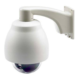
1.3. Feature 1.3.1. Profile of EPTZ3100/EPTZ3100I EPTZ3100 Wall Mount Bracket Top housing Outer housing Sun shield (optional) Camera main body Bubble Camera module EPTZ3100I Top housing Camera Outer housing main body Bubble Camera Module... -
Page 10: Eptz3100/Eptz3100I Base Board
1.3.2. EPTZ3100/EPTZ3100I Base Board The base board that is inside the top housing connects to power cable, video cable, control cable, alarm cable and fan. In order to connect to cables, the board needs to be taken off, and put back after finishing connecting to all cables. The connectors of cable names are marked on the board in white text. - Page 11 Pin # Function ALM_NO_B (Alarm Output Normal Open B) ALM_COM_B (Alarm Output Common B) ALM_NC_B (Alarm Output Normal Close B) ALM_NO_A (Alarm Output Normal Open A) ALM_COM_A (Alarm Output Common A) ALM_NC_A (Alarm Output Normal Close A) ALMIN1 (Alarm Input 1) GND (Ground) ALMIN2 (Alarm Input 2) ALMIN3 (Alarm Input 3)
-
Page 12: Eptz3100/Eptz3100I Quick Operation Guide (Work With Ekb500)
1.4. EPTZ3100/EPTZ3100I Quick Operation Guide (Work with EKB500) EPTZ3100/EPTZ3100I and EKB500 (Keyboard) can work together by using factory default setting. You just need to connect cables by the following steps: 1. Connect the RS-485 cable to EPTZ3100/EPTZ3100I and a keyboard (EKB500). 2. -
Page 13: Eptz3100/Eptz3100I Installation
2. EPTZ3100/EPTZ3100I INSTALLATION 2.1. Packing List There are 3 boxes that are camera main body with a camera module, top housing with a base board & pin connector and outer housing with bubble, plus one tool packet in the package. The detail accessories are listed below: Standard Camera Main Body x 1 Top Housing x1... - Page 14 * EKB500 (Keyboard) * EKB200 (USB Controller Keyboard)
-
Page 15: Cable Needed
2.2. Cable Needed Yellow RS485+ Orange RS485- VIDEO 24VAC Power Cable An adapter with 24VAC/3.5A output provides the power to the EPTZ3100/EPTZ3100I. An extension power line may be needed. Note: The input AC voltage range of an adapter depends on different area. Please make sure the voltage range before installing. -
Page 16: Address Setting
terminal resistance settings. All of the settings should be confirmed before the dome is installed. The control-related setting that is address, communication protocol and transmission speed have to be set consistently with the control device such as a keyboard or a DVR. Notice: Please make sure the power is off before setting, and restart the EPTZ3100/EPTZ3100I to enable a new value after changing. - Page 17 1 2 3 4 5 6 7 8 1 2 3 4 5 6 7 8 Protocol/Baud rate ID address Note: You will see the label of Protocol & Baud Rate as well as RS-485 ID address show on the speed dome. White part represents the switch key. For example: for EVF protocol, white keys are all switched downward;...
- Page 18 Switch Address Switch Switch Switch Address Address Address Switch Switch Switch Switch Address Address Address Address Switch Switch Switch Switch Switch Address Address Address Address Address...
- Page 19 Switch Address Switch Switch Switch Address Address Address Switch Switch Switch Switch Address Address Address Address Switch Switch Switch Switch Switch Address Address Address Address Address...
-
Page 20: Communication Protocol Setting
2.3.2. Communication Protocol Setting The 1 and 3 bits are used to set communication protocol. The factory default protocol is EVF. Notice: Please make sure the power is off before setting, and restart the EPTZ3100/EPTZ3100I to enable a new value after changing. Set all of protocol switches to ON;... -
Page 21: Bracket And Speed Dome Installation
2.4. Bracket and Speed Dome Installation 2.4.1. Installation Requirements 1. Installation should be handled by a qualified service agent and should comply with all local regulations. Service personnel should expect potential problems such as surface strength, surface material, falling objects, outer breaches, building vibration or other similar conditions. -
Page 22: Eptz3100 Dome Camera Wall Mount Simple Installation
2.4.2. EPTZ3100 Dome Camera Wall Mount Simple Installation 1. Screw the top housing to bracket by using a hexagon wrench. 2. Put the waterproof silicon pad on top of the bracket base for waterproof purpose. Waterproof silicon pad Bracket base... - Page 23 3. Connect the cable you detached from base board to the RS485 cable, Power cable and video cable you thread from the wall or ceiling. RS485 cable has to be connected via a terminal block. If you need to connect alarm cable, thread the alarm cable through the second hole.
- Page 24 5. Screw in 4 long screws to fix the bracket to bracket base.
-
Page 25: Eptz3100 Dome Camera Wall Mount Installation
2.4.3. EPTZ3100 Dome Camera Wall Mount Installation Note: Installation location that is a wall, a pole or a ceiling needs to support above five times the total weight of the camera assembly (about 16 kg) to avoid shaken images, and dropping. - Page 26 2. Apply the adhesive stripe at back of desiccant pack to the inner side of the top housing. There are totally 3 desiccant packs to be applied. 3. When all the desiccant packs are pasted and alarm cables are connected properly, put the base board back to its original place, you will need to pull open the switch in order to have the base board fitted to the top housing.
- Page 27 4. Put the waterproof silicon pad on top of the base board for waterproof purpose. Waterproof silicon pad Base board 5. Connect the cable you detached from base board to the RS485 cable, Power cable and video cable you thread from the wall or ceiling. RS485 cable has to be connected via a terminal block.
- Page 28 6. Screw in 4 screws for mounting the bracket base. 7. Thread the cable through the bracket.
- Page 29 8. Screw the top housing to bracket by using a hexagon wrench. 9. Screw in 4 long screws to fix the bracket to bracket base.
- Page 30 10. Pull the hole of base board to open it again. Connect the power and RS485 wires back to power pin and RS485 pin. If you need to connect alarm, connect alarm cable to alarm pin. 11. Hold and push the main body toward the bracket until it is firmly fixed to the bracket. To release it, press orange buttons at both sides of the body.
- Page 31 Note 1: When you push the orange buttons to detach the main body from bracket, please hold the main body carefully, otherwise it may fall down. Note 2: Aim the Arrow label of the main body to the same Arrow label of the bracket when you need to push the main body toward bracket.
-
Page 32: Eptz3100 Dome Camera Ceiling Mount Installation
Note 1: In order to protect the bubble from dirt and scrape, please put on the gloves before installing the bubble. Note 2: The camera module on the mechanical part is very sensitive. Please be careful when installing this part. 13. - Page 33 2. Screw the 3 screws of EPTZ top housing to the 3 holes of indoor recessed mount bracket. 3. Put the indoor recessed mount bracket to the hole that you just made on ceiling. 4. Use a screwdriver to turn the rotation clips (x 3) until they firmly fix to the ceiling. rotation clip →...
- Page 34 5. Snap main body to the indoor recessed mount bracket. NOTE: Aim the Arrow label of the main body to the same Arrow label of the bracket when you need to push the main body toward bracket. 6. Turn the housing of speed dome until it fixes to the top housing.
- Page 35 7. Aim bracket’s fillister to surface ring’s fillister, turn it until it is firmly fixed.
-
Page 36: Bracket And Adapter
2.5. Bracket and Adapter 2.5.1. Indoor Ceiling Pendent Mount Bracket The indoor ceiling pendent mount bracket is used for installing a speed dome on the ceiling. 2.5.2. Pole Mount Adapter The pole adapter is used for installing a wall mount bracket to a pole indoors or outdoors. -
Page 37: Corner Mount Adapter
2.5.3. Corner Mount Adapter The corner mount is used for installing a wall mount bracket to a 270° corner of walls indoors or outdoors. 2.5.4. Indoor Concrete Ceiling Mount Adapter Indoor Concrete Ceiling Mount Adapter is used for indoor installation to concrete ceiling. -
Page 38: Eptz3100/Eptz3100I Camera Setup Menu
3. EPTZ3100/EPTZ3100I CAMERA SETUP MENU In this section, setup and operation guide of EPTZ3100/EPTZ3100I will be introduced. There are 9 items of the setting menu. 3.1. Structure of the Setup Menu Press MENU to enter camera setup menu. Turn the Joystick up/down to change subentries, and right/left to change the setting. If there is an arrow at the end of selection, it means that selection has a sub-menu, please press Enter key of keyboard to enter sub-menu. -
Page 39: Video Settings
3.2. VIDEO SETTINGS In main menu, turn joystick Up / Down to select VIDEO SETTINGS. Turn joystick Left / Right to enter VIDEO SETTINGS sub-menu (see diagram 3.2). EXPOSURE VIDEO SETTINGS <┘ POSITIONS FOCUS MODE ONE PUSH OSD/AREAS DIGITAL ZOOM AUTO MODES WHITE BALANCE OUTDOOR... - Page 40 EL.SHUTTER: Select electronic shutter mode from the options of the menu. There are AUTO, A.FLK , 1/50, 1/160 , 1/250 , 1/1000 , 1/2500, 1/10000, 1/120,000, X2, X4, X6 and X8. AUTO: The AUTO electronic shutter mode is enabled. The shutter speed is controlled automatically according to the brightness of the screen A.FLK: Anti-Flicker.
-
Page 41: Focus Mode
sec for PAL. AUTO X8, AUTO X12, AUTO X16, AUTO X32, AUTO X64, and AUTO X128 work the same as AUTO X4 with different times of shutter speeds. NOTE: If EL. SHUTTER is selected, SLOW SHUTTER will be disabled. IRIS MODE: AUTO mode or MANUAL mode can be selected. MANUAL: The brightness of the image can be adjusted. -
Page 42: Digital Zoom
MANUAL: Enable the manual focus mode. 3.2.3. DIGITAL ZOOM Magnification of the digital zoom can be selected among OFF, 2X, 4X and 8X. OFF: Disable the digital zoom function. 3.2.4. WHITE BALANCE The white balance function corrects the abnormal white color into the normal white color under any color temperature lighting. -
Page 43: Dig. Noise Reduce
increased sensitivity in low light environments. Select from AUTO, DAY and NIGHT NIGHT: IR cut filter is always removed (ICR ON). DAY: IR cut filter is always attached (ICR OFF). AUTO: Auto Day/Night mode switch. The camera will automatically switch the settings needed for attaching or removing the IR cut filter. -
Page 44: Exit
Notice: When the wide dynamic range is ON, some part of the image may appear solarized. This is normal for the wide dynamic range, and is not a camera malfunction. 3.2.8. EXIT Select Exit to save settings and exit from current page. -
Page 45: Positions
3.3. POSITIONS In main menu, turn joystick Up or Down to select POSITION option. Press Enter key or turn joystick Left / Right to enter POSITION sub-menu (see diagram 3.4). VIDEO SETTINGS POSITIONS OSD/AREAS SET POSITIONS <┘ AUTO MODES FREEZE PICTURE ALARM EXIT PRIVATE ZONES... - Page 46 PRESET NO. 1 POSITION <┘ SPEED DWELL TIME (S) MOVE TO POSITION FOCUS MODE MANUAL IRIS+: SAVE AND RETURN WHITE BALANCE AUTO TITLE DEFAULT RETURN (diagram 3.6) POSITION: Select from SET and CLEAR. SET: Select SET and press Enter key of keyboard, you will be entered to a sub-menu. Turn the joystick to your desired position.
- Page 47 SPEED: Select the speed for the preset position. The value is from 1 to 255 and 255 is the highest speed. DWELL TIME (S): Select the dwell time (in second) for the preset position from 1 to 99. FOCUS MODE: Select focus mode for the preset position from MANUAL, ONE PUSH and AUTO.
-
Page 48: Osd/Areas
3.4. OSD/AREAS In main menu, turn joystick Up or Down to select OSD/AREAS. Turn joystick Left or Right to enter OSD/AREAS sub-menu (see diagram 3.8) VIDEO SETTINGS POSITIONS CAM. TITLE EPTZ3100__ OSD/AREAS AREAS <┘ AUTO MODES DIRECTIONS <┘ ALARM DISPLAY <┘... - Page 49 In zone menu, you can set a zone and name it, when the speed dome turns to the zone you set, it will display zone name on the screen (only if “OSD/AREAS->Display -> Zone” is set as “YES”). Turn the joystick to Up/Down to select the character. Turn the joystick Left or Right to select the character position.
-
Page 50: Directions
Turn joystick Right/Left to highlight the zone you have set and turn the joystick Up/Down to select another zone number. If you wish to clear the zone you have set, go to “CLR” and press Enter key. 3.4.3. DIRECTIONS Press Enter key of keyboard or turn joystick Left/Right to enter DIRECTIONS sub-menu (see diagram 3.12) DIRECTIONS NORTH SET NORTH... - Page 51 3. Press IRIS+ key of keyboard to save and return. DIRECTIONS NORTH SET NORTH <┘ DEFAULT NORTH [PUSH ENT] RETURN (diagram 3.14) 4. Go to “DEFAULT NORTH” and press Enter key to set the north position as default north position. 5.
-
Page 52: Display
3.4.4. DISPLAY Press Enter key of keyboard or turn joystick Left/Right to enter DISPLAY sub-menu (see diagram 3.15) SHOW OSD CAMERA TITLE CAM. TITLE EPTZ3100__ DIRECTIONS AREAS <┘ ZONES DIRECTIONS <┘ PRESET TITLE DISPLAY <┘ ZOOM EXIT MOTION CAMERA STATUS RETURN (diagram 3.15) 1. - Page 53 4. ZONES YES: show zones NO: do not show zones 5. PRESET TITLE YES: show preset title NO: do not show preset title 6. ZOOM YES: show zoom multiple when zoom in or zoom out. NO: do not show zoom multiple. 7.
-
Page 54: Exit
3.4.5. EXIT Select Exit to save settings and exit from current page. 3.5. AUTO MODES In main menu, turn joystick Up/Down to select AUTO MODES. Turn joystick Left/Right to enter AUTO MODES sub-menu (See diagram 3.16) AUTOPAN VIDEO SETTINGS <┘ PRESET TOURS POSITIONS <┘... - Page 55 a. ENDLESS MODE ON: enable endless mode. The speed dome will perform 360 degree endless auto-pan. OFF: disable endless mode. The speed dome will perform auto-pan between position left and position right. b. SPEED Select speed from 1~255 and 255 is the highest speed. c.
- Page 56 AUTOPAN ENDLESS MODE SPEED DWELL TIME L (S) DWELL TIME R (S) MOVE TO POSITION SET LEFT POS. <┘ IRIS+: SAVE AND RETURN SET RIGHT POS. <┘ DEFAULT IRIS-: RETURN (diagram 3.18) f. SET RIGHT POS. Press Enter key or turn the joystick Left/Right to enter SET RIGHT POS. menu. Turn the joystick to the position where you wish to set RIGHT position.
-
Page 57: Preset Tours
g. DEFAULT ON: all settings in AUTOPAN menu will be returned to default values. OFF: the setting in AUTOPAN menu is not default value. h. RETURN Turn joystick Left/Right to return to previous menu 3.5.2. PRESET TOURS Press Enter key or turn the joystick Left/Right to enter PRESET TOURS sub-menu (see diagram 3.20) TOUR NO. -
Page 58: Pattern
setting of preset position. e. PREV PAGE/NEXT PAGE: Turn the joystick Left to go previous page or turn joystick Right to go next page. f. RETURN: Turn joystick Left/Right to return to previous menu. 3.5.3. PATTERN Press Enter key of keyboard to enter PATTERN sub-menu (see diagram 3.21) AUTOPAN <┘... -
Page 59: Auto Resume
d. Turn the joystick to record the tour you wish to set. Press IRIS+ when you finish setting pattern tour. Press IRIS- if you wish to cancel this action. At duration column of PATTERN SETUP menu, you will see the duration time of pattern you set. e. -
Page 60: Power Up Func
MODE, POS.1 (H), TOUR1, PAT.1 and AUTOPAN. 3.5.6. POWER UP FUNC Turn the joystick Left or Right to select the mode to return to when power failure occurs. It is selectable from PREV MODE, POS.1 (H), TOUR1, PAT.1, AUTOPAN and OFF 3.5.7. - Page 61 Go to INPUT NO. selection and turn the joystick Left/Right to select alarm input number from 1 ~4. Type: Select Normal Close (NC), Normal Open (NO), NIGHT NC, NIGHT NO, or OFF for alarm type. NC: Enable a normal close alarm input. NO: Enable a normal open alarm input.
- Page 62 PATTERN: When the alarm is triggered, speed dome will run the pattern. Turn the joystick Left/Right to select on Pattern and press Enter key to select pattern number. Turn joystick Left/Right to make selection. It is selectable from1~4. Press Enter key again to confirm selection.
-
Page 63: Alarm Outputs
3.6.2. ALARM OUTPUTS Press Enter key of keyboard to enter ALARM OUTPUTS sub-menu. (see diagram 3.26) ALARM OUTPUT TRIGGER ALARM INPUTS <┘ ALARM OUTPUTS <┘ OUTPUT NO MOTION DETECT <┘ INPUT1 EXIT INPUT2 INPUT3 INPUT4 MOTION SYSTEM ERROR NO REMOTE RETURN (diagram 3.26) a. -
Page 64: Motion Detect
Select NO to disable this function. i. RETURN: RETURN to the previous menu. 3.6.3. MOTION DETECT Press Enter key of keyboard to enter MOTION DETECT sub-menu. (see diagram 3.27) ALARM INPUTS <┘ MOTION DETECT 1 ALARM OUTPUTS <┘ SENSITIVITY MOTION DETECT <┘... -
Page 65: Private Zones
3.7. PRIVATE ZONES In main menu, turn joystick Up/Down to select PRIVATE ZONES masking. Turn joystick Left/Right to enter PRIVATE ZONE sub-menu (see diagram 3.29) PRIVATE ZONE 1 ON VIDEO SETTINGS <┘ POSITIONS PRIVATE ZONE 1 OFF OSD/AREAS PRIVATE ZONE 1 OFF AUTO MODES PRIVATE ZONE 1 OFF ALARM... - Page 66 c. Select the area to be covered first. Turn joystick Left/Right to adjust width of the private zone area. Turn joystick Up or Down to adjust height of the private zone area. Press IRIS- key to set private zone position. Press IRIS+ to save and return to previous menu.
-
Page 67: System
3.8. SYSTEM In main menu, turn joystick Up/Down to select SYSTEM. Turn joystick Left/Right to enter SYSTEM sub-menu (see diagram 3.32) VIDEO SETTINGS AUTO INIT POSITIONS LANGUAGE ENGLISH OSD/AREAS PASSWORD <┘ AUTO MODES LOAD DEFAULT [PUSH ENT] ALARM RESTART [PUSH ENT] PRIVATE ZONES EXIT SYSTEM... -
Page 68: Info
PASSWORD ACTIVE: Select YES to activate password mode. Select NO to disable password mode. ENTER PASSWORD: Enter the password VERIFY PASSWORD: Enter the password again to confirm your input. Press IRIS+ key to save and return to previous menu. Press IRIS- key to cancel. SAVE AND RETURN: Turn joystick Left/Right to save the changes and return to previous menu. -
Page 69: Exit
c. BAUDRATE: shows baud rate of this speed dome d. RS-485-ID: shows RS-485 ID of this speed dome e. PRESET-CNT: Preset counter. This counter counts the preset movement, and 1 is counted when the speed dome runs to preset position. f. -
Page 70: Eptz3100/3100I Function Setup And Operation
4. EPTZ3100/3100I FUNCTION SETUP AND OPERATION 4.1. Manual Control Mode Manual control: Shift Joystick Up/Down/Left/Right, and turn it Clockwise/Counterclockwise to control speed dome. Use the control keys which are Zoom, Focus and IRIS function keys on the keyboard to Zoom In/Out, focus N (near)/F (Far), or IRIS +/-. Note: Zoom In/Out control keys will be disabled when entering to OSD menu mode. -
Page 71: Position Setting
4.3. Position Setting Focus on a preset position: Press the number key, and then press Position to focus on the number of preset position; or you can press Position, then enter the preset position number, and then press Enter to focus on the number of preset position. -
Page 72: Tour Mode
speed. Dwell time: default is 2 sec; It can be changed by EVF Keyboard Set + A.Pan setting dwell time of A pos or B pos. 99 => Auto scan (360 degree) Default speed is 32. It can be changed by EVF Keyboard (Shift + A.Pan setting speed). -
Page 73: Alarm Link To A Position/Tour
One-way tour Mode: Press Tour to enter the tour mode. The system will ask you to enter the tour number you would like to run, and starts the tour after pressing Enter. To preset a tour before running is necessary. Preset a one-way tour: Press Set + Tour to preset a one-way tour. -
Page 74: Other Operations
If you set the position number to 99, the dome will do a 360 degree auto scan or AB two point pan if limit is ON. If you set the position number to 98, the dome will do a frame scan. Delete an alarm link: Press Clr + F1 to delete a link of alarm to position/tour. - Page 75 EverFocus Electronics Corp. Europe Office: Head Office: Albert-Einstein-Strasse 1 12F, No.79 Sec. 1 Shin-Tai Wu Road, D-46446 Emmerich, Germany Hsi-Chih, Taipei, Taiwan TEL: +49(0)-2822-9394-0 TEL: +886-2-26982334 FAX: +49(0)-2822-9394-95 FAX: +886-2-26982380 www.everfocus.de www.everfocus.com.tw China Office: USA L.A. Office: Room B-05D-1, KESHI PLAZA, 1801 Highland Ave.