Table of Contents
Advertisement
Quick Links
Advertisement
Table of Contents

Related Manuals for EverFocus Day / Night Speed Dome Camera EPTZ 100


Summary of Contents for EverFocus Day / Night Speed Dome Camera EPTZ 100
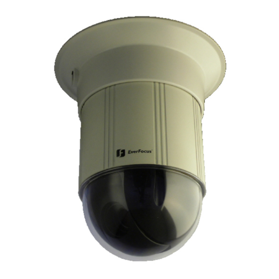
- Page 1 EPTZ 100 Day / Night Speed Dome Camera INSTALLATION / OPERATION...
-
Page 2: Safety Warnings
Therefore, all specifications are subject to change without prior notice. Misprints reserved. Please read this manual carefully before installing and using this unit. Be sure to keep it handy for later reference. Ihr EverFocus Produkt wurde entwickelt und Your EverFocus product is designed and... -
Page 3: Table Of Contents
Privacy Mask ... 36 4.1.9 Alarm... 37 4.1.10 Initialize... 37 4.1.11 OPERATION WITH EKB 500 KEYBOARD ... 38 EKB 500 operation with EverFocus protocol (EVF-2) ... 39 EPTZ 100 setup menu... 40 5.1.1 Preset positions ... 40 5.1.2 Autopan ... 40 5.1.3 Preset tours... - Page 4 COM PORT SETTING - RS-485 interface setting... 45 DEVICE SETTING > CAMERA ... 45 APPENDIX B: Basic Settings at EverFocus DVR ... 46 EDR / EDVR / EDSR series (except EDSR100, EDSR100H) ... 46 ECOR / PARAGON series ... 46 Appendix C: Troubleshooting...
-
Page 5: Introduction
360° endless pan • Digital Noise Reduction • 4-zone privacy masking • RS-485 communication with EverFocus, Pelco-D and Pelco-P protocol • 4x 10 minutes pattern tour (programmable camera movement) • 3 alarm inputs, 1 alarm output relay • Includes adapter for ceiling surface mount and recessed ceiling mount. -
Page 6: Specifications
1,5 m auto, one-push AF, manual RS-485 simplex 2 wire EverFocus / Pelco-P / Pelco-D , setup by DIP switch 2400 / 4800 / 9600 bps, setup by DIP switch 1 ~ 255, setup by DIP switch 3 inputs, 1 output, with tour / position auto triggering 360°... - Page 7 Alarm: Proportional pan speed: Privacy zones: Setup: Auto resume: Video output: Power Power source: Power consumption: Physical / environment Connectors: Ambient temperature: Humidity: Protection rating: Dimensions: Weight: Delivery scope: 3 inputs, 1 output, with tour / position auto triggering 4 zones, free adjustable multiline OSD setup menu after 1, 2, 3, 4, 5 or 10 min.
-
Page 8: Dimensions
2.5 DIMENSIONS 2.5.1 Dimensions with ceiling mount adapter 2.5.2 Dimensions with recessed ceiling mount adapter EPTZ100_ma_en_rev03.doc... -
Page 9: Dimension Eptz 100 With Wall Mount Bracket Eptz 100 Wlm
2.5.3 Dimension EPTZ 100 with wall mount bracket EPTZ 100 WLM 2.5.4 Dimensions wall bracket EPTZ 100 WLM EPTZ100_ma_en_rev03.doc... -
Page 10: Dimension Eptz 100 With Ceiling Pendant Bracket Eptz 100 Cpm
2.5.5 Dimension EPTZ 100 with ceiling pendant bracket EPTZ 100 CPM 2.5.6 Dimension ceiling pendant bracket EPTZ 100 CPM EPTZ100_ma_en_rev03.doc... -
Page 11: Installation
3 INSTALLATION 3.1 MECHANICAL 3.1.1 Ceiling mount The ceiling mount accessories are included in the EPTZ 100 package. 1. Use the drilling template to mark the drilling holes. 2) Click the connector board into the ceiling adapter. Follow the red arrow marks at board and ceiling adapter for correct position. -
Page 12: Recessed Ceiling Mount
3.1.2 Recessed ceiling mount Recessed ceiling mount is possible at open ceilings. A metal ring has to be mounted at ceiling side. 1) Cut a 115mm / 4.6" hole into the ceiling. 2) Drill 3 screw holes for mounting in the ceiling Use the metal ring as template for drilling holes. -
Page 13: Wall Mount
3.1.3 Wall mount Wall mount requires the optional bracket EPTZ 100 WLM. 1) Assemble the connector board to the bracket adapter by 3 M4 screws. Follow the red arrow marks at both board and ceiling adapter for correct position. 2) Remove the cable cover from the wall bracket. 3) Mount the bracket adapter with connector board to the bracket. -
Page 14: Ceiling Pendant Mount
3.1.4 Ceiling pendant mount Ceiling pendant mount requires the optional adaptor EPTZ 100 CLM. 1) Assemble the connector board to the bracket adapter by 3 M4 screws. Follow the red arrow marks at board and ceiling adapter for correct position. 2) Mount the bracket adapter with the connector board to the EPTZ 100 CLM. -
Page 15: Electrical
3.2 ELECTRICAL 3.2.1 Video EPTZ 100 provides a composite 1 Vp-p video output PAL/NTSC (video system depending on ordered version) with a BNC cable socket. Cameras and video displaying or processing equipment (DVRs, switchers etc.) require cabling with 75 Ohm video cable, e.g. RG-59, RG-12, and suitable BNC plugs. Due to inappropriate absorbability, 50 Ohm coax cable (e.g. -
Page 16: Rs-485
3.2.3 RS-485 EPTZ 100 uses RS-485 simplex wiring; the signal is transferred via a single twisted pair line. CAT5 network cable is recommended, UTP version (unshielded) is sufficient for normal application. A shielded cable should be used if the installed cables are expected to be highly susceptible to interferences. Basically, the bus should be created by serial wiring, star wiring is only permitted using signal distributors. - Page 17 3.2.3.1 RS-485 installation with EKB 500 keyboard For connection to EKB 500 via RS-485, it is recommended to use the EKB 500 connector box. The drawing below shows an installation example. Please make sure that the wires are connected with correct polarity. Alternatively, it is possible to connect the RS-485 wire directly to the keyboard by using a standard RJ45 plug.
- Page 18 3.2.3.2 RS-485 installation with EverFocus DVR It is possible to control the EPTZ 100 speed dome by EverFocus DVR (except 1 Ch. models) via network. A combined local control by EKB 500 keyboard and remote (network) control by DVR is also possible.
-
Page 19: Alarm
3.2.4 Alarm EPTZ 100 provides 3 alarm input contacts and 1alarm output relay. It is also possible to trigger the alarm output relay by EKB 500 keyboard command. For input contacts, use dry Normal Open (N.O.) contacts only. The maximum load of output relay contacts is 30 V AC/DC 0.5 A max. EPTZ100_ma_en_rev03.doc... -
Page 20: Communication Settings
COMMUNICATION SETTINGS The setup for general RS-485 parameters - protocol type, RS-485 address and baud rate - is done by DIP switches, located at the top of the camera module. Correct settings are essential for communication with the dome controller. For correct communication, all 3 parameters - protocol, baud rate and RS-485 ID- have to comply with the PTZ controller settings. -
Page 21: Rs-485 Id (Address)
3.3.2 RS-485 ID (address) The RS-485 ID (address) setting is done by DIP switch DS2. The following table shows the switch positions for the possible addresses 1 ~ 255: EPTZ100_ma_en_rev03.doc... - Page 22 EPTZ100_ma_en_rev03.doc...
-
Page 23: Initial Start
Please check these information to ensure the correct DIP switch settings. Example: TYPE: EPTZ100 Firmware: 709M/809Q BAUDRATE:9600 RS-485 ID: 1 PROTOCOL: EVERFOCUS 4 OSD MENU SETUP 4.1.1 Operation in Setup Menu Start EPTZ menu: Switch between the settings: Enter submenus:... -
Page 24: Menu Structure
4.1.2 Menu Structure OSD Structure Part 1: MAIN MENU SYSTEM INFO SYSTEM INFO TYPE DISPLAY FIRMWARE CAMERA BAUDRATE SCAN RS-485 ID CONTROL PROTOCOL PRIVACY MASK DISPLAY ALARM CAMERA ID INITIALIZE CAMERA NAME EXIT PRESET NUMBER PRESET NAME PTZ POSITION CAMERA ZOOM SPEED ADVANCED SETUP RESCUE MODE... - Page 25 OSD Structure Part 2: MAIN MENU SYSTEM INFO DISPLAY CAMERA SCAN CONTROL CONTROL PRIVACY MASK AUTO RESUME ALARM POWER ON RESUME INITIALIZE IMAGE FLIP EXIT PRIVACY MASK MASK 1 MASK 2 MASK 3 MASK 4 ALARM RELAY INPUT 1 INPUT 2 INPUT 3 OUTPUT INITIALIZE...
-
Page 26: Main Menu
EPTZ100 TYPE 709M809Q FIRMWARE 9600 BAUD RATE RS-485 ID EVERFOCUS PROTOCOL 4.1.5 Display The settings in this menu define the overlay displays of the camera. CAMERA ID Shows the RS-485 ID on the screen: ON: display of RS-485 ID OFF: no display of RS-485 ID CAMERA NAME With setting ON, a camera title with up to 16 characters can be entered. -
Page 27: Camera
4.1.6 Camera This menu provides the camera video settings. CAMERA Zoom speed setup in 8 possible levels: ZOOM SPEED Level 1: slowest to Level 8: fastest Opens submenu for camera features (following chapter) ADVANCED SETTING Mode for recovering serial communication between speed dome and camera RESCUE MODE module. - Page 28 BACKLIGHT Back light compensation improves the image quality in scenes with extreme light behind the object which usually washes out the image considerably. Back light function is used to reduce, if necessary, both exposure time and video gain to avoid over-exposure. Use the back light compensation for sceneries with back light only;...
- Page 29 ZOOM POS INIT LENS INIT EXPOSURE BRIGHTNESS IRIS SHUTTER SSNR SENS-UP Defines a zoom position after powering up the camera, range is x1 ~ x10 Reset of the autofocus lens in case of malfunction Return to CAMERA ADVANCED SETTING page Image brightness setting, range 1~100 Mode of the lens iris: AUTO:...
- Page 30 SPECIAL Submenu for advanced camera functions: USER PRESET PRIVACY DAY/NIGHT SYNC: COMM ADJ IMAGE ADJ RESET Reset of the camera parameters to factory defaults. EXIT Return to CAMERA menu. Not supported by EPTZ 100 Keep OFF setting, privacy mask setup is done in the PRIVACY MASK menu, available in the main menu Modes of the day/night switching: B/W : black/white (night) mode, IR cut filter switched off...
-
Page 31: Scan
4.1.7 Scan This menu contains all setup options for automatic dome modes such as autopan, preset tours and pattern. SCAN AUTO PAN ALL PRESET GROUP SCAN TOUR SCAN PATROL PATTERN AUTO PAN PAN/TILT PAN ONLY This autopan mode performs pan and tilt movements between 2 points. - Page 32 CIRCLE RETURN ALL PRESET This type of preset tour includes all programmed preset positions. GROUP SCAN Pre-defined preset tours with 4 preset positions each: Group 1: preset positions 1~4 Group 2: preset positions 5~8 Group 3: preset positions 9~12 Group 4: preset positions 13~16 GROUP1 GROUP2 GROUP3...
- Page 33 TOUR SCAN Combined preset tour with selected GROUP tours. PATROL The PATROL tour is the most flexible preset tour with selected presets as well as individual speed and dwell time setting for each preset. The maximum number of preset positions in this tour is 32 (preset numbers 1~32) . GROUP1 Group1 included in tour OFF: Group1 skipped in tour...
- Page 34 PATTERN A pattern is a programmed course of camera movement. EPTZ 100 can store 4 patterns with a maximum length of 10 minutes each. RETURN Select a pattern for programming / checking. RECORD Start the movement programming with "Go To Preset 1".
-
Page 35: Control
4.1.8 Control This menu provides settings for resume function after inactivity, power-up and special functions. AUTO RESUME OFF/ON > POWER ON OFF/ON RESUME IMAGE FLIP OFF/ON RETURN AUTO RESUME is the reaction of the dome after a defined time of inactivity (no operator action). auto resume activated OFF: auto resume not active... -
Page 36: Privacy Mask
4.1.9 Privacy Mask EPTZ 100 allows for masking 4 different areas to protect private or confidential zones in the field of view. MASK1~4 OFF/ON shows the status of the privacy zone: ON: privacy zone masking active OFF: privacy zone off RIGHT enters the submenu to mask setup POSITION Definition of size and position of the privacy zone:... -
Page 37: Alarm
4.1.10 Alarm In this menu, the alarm reactions for input contacts are defined. RELAY OFF/ON INPUT1...3 PRESET x OUTPUT OFF/ON RETURN 4.1.11 Initialize POWER ON RESET CAMERA DEFAULT FACTORY DEFAULT LENS REFRESH x DAYS CAMERA REFRESH x DAYS It is possible to switch the output relay remotely with this menu item for test purpose: output relay switched OFF:... -
Page 38: Operation With Ekb 500 Keyboard
5 OPERATION WITH EKB 500 KEYBOARD The following chapter describes the EPTZ 100 operation with EKB 500 keyboard (with firmware 1.5 or higher). EPTZ 100 is optimized for protocol type EVF-2 of EKB 500 keyboard. Basic communication settings for EKB 500 are described in APPENDIX A. For further details, please refer to the EKB 500 user manual. -
Page 39: Ekb 500 Operation With Everfocus Protocol (Evf-2)
5.1 EKB 500 OPERATION WITH EVERFOCUS PROTOCOL (EVF-2) Operation outline Function Keys / operation Open dome menu Switch menu functions Change menu settings Leave dome menu Pan/tilt Zoom TELE / WIDE TELE: WIDE: Focus TELE: Iris open / close Open iris:... -
Page 40: Eptz 100 Setup Menu
5.1.1 EPTZ 100 setup menu Start EPTZ menu: Switch between the settings: Enter submenus: Change the settings: EXIT OSD menu / submenus: Note: Exceptional commands are described in the OSD. 5.1.2 Preset positions Up to 64 preset PTZ positions can be stored in EPTZ 100. Save presets (hold) + >... -
Page 41: Preset Tours
5.1.4 Preset tours EPTZ 100 provides 7 different preset tour modes. All tours are defined in OSD setup menu. 1. PATROL TOUR: Preset tour with up to 16 selected presets. 2. ALL PRESET TOUR: Preset tour with all available presets. 3. -
Page 42: Ekb 500 Operation With Pelco-D/P Protocol
EKB 500 OPERATION WITH PELCO-D/P PROTOCOL NOTE: Not all EPTZ 100 functions are available in PELCO-D/P protocol. Operation for ssome functions is different to operation with EVERFOCUS protocol. 5.2.1 EPTZ 100 setup menu Start EPTZ 100 menu: Switch between the settings:... -
Page 43: Autopan
5.2.3 Autopan The speed for autopan function is programmed in the OSD menu; the entered value for speed in EKB 500 will be ignored at start of autopan. Activate A-B autopan (pan/tilt between 2 points) N (Pelco-P only) Alternative: N > 9 >... -
Page 44: Remote Switching Of Eptz 100 Output Relay
5.2.6 Remote switching of EPTZ 100 output relay The EKB 500 keyboard provides the option to switch the output relay of EPTZ 100 On / Off. Switch relay ON: > > > > Alternative: N > 2 > Switch relay OFF: Alternative: N >... -
Page 45: Appendix A: Basic Settings At Ekb 500 Keyboard
Press Enter to confirm the setting and Enter the RS-485 address of the EPTZ 100. If the camera is connected to an EverFocus DVR, enter the DVR number and video input number. Enter any value if no DVR is connected (numeric entry compulsory). -
Page 46: Appendix B: Basic Settings At Everfocus Dvr
7 APPENDIX B: BASIC SETTINGS AT EVERFOCUS DVR The following settings are required to establish RS-485 communication between DVR and speed dome: 7.1 EDR / EDVR / EDSR SERIES (EXCEPT EDSR100, EDSR100H) 1. CAMERA menu: enter the correct RS-485 ID (address) at the speed dome camera channel. -
Page 47: Appendix C: Troubleshooting
8 APPENDIX C: TROUBLESHOOTING 8.1 GENERAL MALFUNCTION In case of drifted preset position or abnormal reaction of EPTZ 100 speed dome perform a reset of the dome, for the reset 3 options are possible: Option 1: Setup menu > INITIALIZE > POWER ON RESET Option 2: (GoTo) POSITION 80 Option 3:... - Page 48 EverFocus Electronics Corp. Head Office: 12F, No.79 Sec. 1 Shin-Tai Wu Road, Hsi-Chih, Taipei, Taiwan www.everfocus.com.tw USA Subsidiary: 1801 Highland Ave. Unit A Duarte, CA 91010, U.S.A. www.everfocus.com European Subsidiary: Albert-Einstein-Straße 1 D-46446 Emmerich am Rhein, Germany www.everfocus.de China Subsidiary:...