Table of Contents
Advertisement
Quick Links
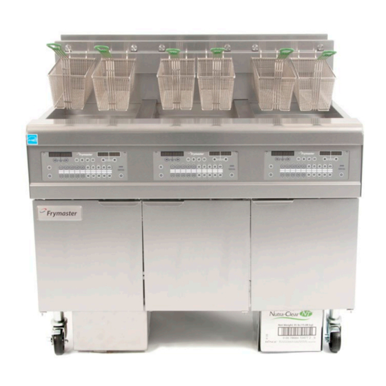
Oil Conserving Fryer (OCF)
FPGL30 Gas Fryer
Installation, Operation and Maintenance
Manual
This manual is updated as new information and models are released. Visit our website for the latest manual.
FOR YOUR SAFETY
Do Not Store or use gasoline
or other flammable vapors
and liquids in the vicinity of
this or any other appliance.
*8196687*
Part Number: FRY_IOM_8196687 01/2019
Original Instructions
Your Growth Is Our Goal
READ THE INSTRUCTIONS BEFORE USING THE FRYER.
Read these instructions for use carefully so as to
familiarize yourself with the appliance before
connecting it to its gas supply.
Keep these instructions for future reference.
™
CAUTION
Advertisement
Table of Contents
Troubleshooting

Related Manuals for Frymaster FPGL30


Summary of Contents for Frymaster FPGL30
- Page 1 Your Growth Is Our Goal Oil Conserving Fryer (OCF) ™ FPGL30 Gas Fryer Installation, Operation and Maintenance Manual This manual is updated as new information and models are released. Visit our website for the latest manual. CAUTION FOR YOUR SAFETY READ THE INSTRUCTIONS BEFORE USING THE FRYER.
- Page 2 PART AND/OR PART RECEIVED FROM AN UNAUTHORIZED SERVICER. NOTICE This appliance is intended for professional use only and is to be operated by qualified personnel only. A Frymaster Factory Authorized Servicer (FAS) or other qualified professional should perform installation, maintenance, and repairs. Installation, maintenance, or repairs by unqualified personnel may void the manufacturer’s warranty.
- Page 3 Quick-Disconnect Devices for Use with Gas Fuel, ANSI Z21.41 or CSA 6.9. NOTICE No warranty is provided for any Frymaster fryer used in a mobile or marine installation or concession. Warranty protection is only offered for fryers installed in accordance with the procedures described in this manual. Mobile, marine or concession conditions of this fryer should be avoided to ensure optimum performance.
- Page 4 Do not allow children to play with this appliance. WARNING If the electrical power supply cord is damaged, it must be replaced by a Frymaster Factory Authorized Servicer or a similarly qualified person in order to avoid a hazard.
- Page 5 WARNING Do not overfill the frypot to avoid overflow of hot oil that may cause severe burns, slipping and falling. WARNING Use caution and wear appropriate safety equipment when adding oil to the fryer, to prevent splashing of hot oil, which may cause severe burns.
-
Page 6: Table Of Contents
OCF30 Series Gas Fryers ™ Installation and Operation Manual TABLE OF CONTENTS CHAPTER 1: General Information Applicability and Validity ......................1-1 Safety Information ........................1-1 Controller Information ......................1-2 European Community (CE) Specific Information ..............1-2 Equipment Description ......................1-3 Installation, Operating, and Service Personnel ................ - Page 7 CHAPTER 5: Preventive Maintenance Fryer Preventive Maintenance Checks and Service ..............5-1 Daily Checks and Service ......................5-1 5.2.1 Inspect Fryer for Damage ..................... 5-1 5.2.2 Clean Fryer Cabinet Inside and Out ................5-1 5.2.3 Clean the Built-in Filtration System Daily ..............5-1 5.2.4 Clean Filter Pan, Detachable Parts and Accessories Daily ...........
-
Page 8: Chapter 1: General Information
™ OCF30 SERIES GAS FRYER CHAPTER 1: GENERAL INFORMATION Applicability and Validity ™ ® The OCF30 Series Gas Fryer, with SMART4U technology, has been approved by the Eu- ropean Union for sale and installation in the following EU countries: AT, BE, BG, CH, CY, CZ, DE, DK, EE, ES, FI, FR, GB, GR, HR, HU, IE, IS, IT, LT, LU, LV, MT, NL, NO, PL, PT, RO, SE, SI, SK, TR and TU. -
Page 9: Controller Information
Controller Information FCC COMPLIANCE This equipment has been tested and found to comply with the limits for a Class A digital device, pursuant to Part 15 of the FCC rules. While this device is a verified Class A device, it has been shown to meet the Class B limits. -
Page 10: Equipment Description
Installation, Operating, and Service Personnel Operating information for Frymaster equipment has been prepared for use by qualified and/or authorized personnel only, as defined in Section 1.7. All installation and service on Frymaster equipment must be performed by qualified, certified, licensed, and/or authorized installation or service personnel, as defined in Section 1.7. -
Page 11: Shipping Damage Claim Procedure
QUALIFIED SERVICE PERSONNEL Qualified service personnel are those who are familiar with Frymaster equipment and who have been authorized by Frymaster, L.L.C. to perform service on the equipment. All authorized service per- sonnel are required to be equipped with a complete set of service and parts manuals, and to stock a minimum amount of parts for Frymaster equipment. - Page 12 Quantity Needed: Service information may be obtained by contacting your local FAS/Distributor. Service may also be obtained by calling the Frymaster Service Department at 1-800-551-8633 or 1-318-865-1711 or by e-mail: service@frymaster.com. When requesting service, please have the following information ready:...
-
Page 13: Chapter 2: Installation Instructions
Failure to use qualified, licensed, and/or authorized installation or service personnel (as de- fined in Section 1.7 of this manual) to install, convert to another gas type or otherwise service this equipment will void the Frymaster warranty and may result in damage to the equipment or injury to personnel. -
Page 14: National Code Requirements
Frymaster recommends that the minimum distance be 24 in. (600 mm) from the flue outlet to the bottom edge of the filter when the appliance consumes more than 120,000 BTU per hour. -
Page 15: Electrical Grounding Requirements
2.1.3 Electrical Grounding Requirements All electrically operated appliances must be grounded in accordance with all applicable national and local codes, and, where applicable, CE codes. In the absence of local codes, the appliance must be grounded in accordance with National Electrical Code, ANSI/NFPA 70, or the Canadian Electrical Code, CSA C22.2, as applicable. -
Page 16: Caster/Leg Installation
2. Level fryers equipped with legs by screwing out the legs approximately 1 inch then adjusting them so that the fryer is level and at the proper height in the exhaust hood. Frymaster recommends that the minimum distance from the flue outlet to the bottom edge of the hood be 24 in. -
Page 17: Connection To Gas Line
Place the computer power switch in the OFF position. Verify that the display indicates OFF. 4. Refer to the data plate on the inside of the fryer door to determine if the fryer burner is configured for the proper type of gas before connecting the fryer quick-disconnect device or piping from the gas supply line. - Page 18 DANGER “Dry-firing” your unit will cause damage to the frypot and can cause a fire. Always ensure that cooking oil or water is in the frypot before firing the unit. DANGER All connections must be sealed with a joint compound suitable for the gas being used and all connections must be tested with a solution of soapy water before light- ing any pilots.
- Page 19 NOTICE- Australia Only The air pressure switch on the combustion blower should read: Full Vat units-122pa (0.5 inches W.C.) and for Split Vat units-180pa (0.72 inches W.C.). NOTICE- South Africa Only This appliance requires an operating pressure of 2,8 kPa at the appliance. A suitable LPG regulator that complies with the requirements of SANS 1237 must be installed.
- Page 20 1. Connect the quick-disconnect hose to the fryer quick-disconnect under the fryer and to the building gas line. NOTE: Quick disconnect hoses are not supplied to CE marked fryers. NOTE: Some fryers are configured for a rigid connection to the gas supply line. These units are connected to the gas supply line at the rear of the unit.
-
Page 21: Converting To Another Gas Type
5. Check the programmed temperature thermostat setting. (Refer to chapter 4 3000 Computer Instructions) for the setpoint programming instructions for your particular controller.) Converting to another Gas Type DANGER This appliance was configured at the factory for a specific type of gas. Converting from one type of gas to another requires the installation of specific gas-conversion compo- nents. -
Page 22: Positioning The Fryer
Change the orifices. b. Adjust the manifold pressure. 3. Remove the old rating plate and return to Frymaster. Affix the new rating plate included with the conversion kit in place of the old rating plate stating the gas has been converted. -
Page 23: Installing The Jib Cradle
REAR OF FRONT OF FRYER FRYER Anchor Strap or Chain Restraint Secure Strap or Restraint to floor with appropriate fastener. NOTE: Bent link on Chain Retstraint goes to floor. Leg or Caster Mounting Bolt 2. Close fryer drain-valve(s). 3. Clean and fill frypot(s) to the bottom oil level line with cooking oil. (See Equipment Setup and Shutdown Procedures in Chapter 3.) Installing the JIB Cradle Open the fryer door (typically the far-right door) -
Page 24: Chapter 3: Operating Instructions
™ OCF30 SERIES GAS FRYER CHAPTER 3: OPERATING INSTRUCTIONS ™ FINDING YOU WAY AROUND THE OCF30 SERIES GAS FRYER Flue Cap Basket Hanger Top Cap Control Panel (3000 Controller Bezel shown) JIB reset Drain button Handle Optional JIB Filter Filter Pan (See Sec. -
Page 25: Controller Operation And Programming
3000 Controller Manual 819-6872 for the controller programming and operat- ing procedure. For CM3.5 controllers r efer to the separate Frymaster Fryer Controllers User’s Man- ual furnished with your fryer for the specific controller operating instructions. -
Page 26: Lighting The Fryer
1. Fill the frypot with cooking oil to the bottom OIL LEVEL line located on the rear of the frypot. This will allow for oil expansion as heat is applied. Do not fill cold oil any higher than the bot- tom line;... -
Page 27: Shutting The Fryer Down
Left Viewing Ports are Right Viewing Ports behind the motor housings. The optimum burn is a bright orange-red glow. If a blue flame is observed, or if there are dark spots on a burner face, adjust the air gas mixture as follows: On the side of the blower housing opposite the motor is a plate with a locking nut. -
Page 28: Oil Attendant™ Automatic Topoff
3.4 Optional Oil Attendant™ Automatic Top-Off When the Oil Attendant™ top-off oil sys- tem is in place on the fryer, oil is continu- ally topped off in the frypots from a reser- voir in the cabinet. The reservoir holds a 35 pound box of oil. -
Page 29: Routine Oil Changes
3.4.2 Routine Oil Changes When the oil reservoir level is low, the controller displays TOPOFF OIL EMPTY in the left display and CONFIRM in the right display. Press (CONFIRM). Some procedures may differ from photos shown. Follow manufactures instructions for changing the JIB. If using solid shortening see Appendix B in the rear of this manual for instructions. -
Page 30: Chapter 4: Filtration Instructions
™ OCF30 SERIES GAS FRYERS CHAPTER 4: FILTRATION INSTRUCTIONS WARNING The on-site supervisor is responsible for ensuring that operators are made aware of the inherent hazards of operating a hot oil filtering system, particularly the aspects of oil filtration, draining and cleaning procedures. Preparing the Built-In Filtration System for Use The FootPrint Pro filtration system allows the oil in one frypot to be safely and efficiently filtered while the other frypots in a battery remain in operation. - Page 31 2. Inspect the filter pan connection fitting to ensure that Inspect the filter both O-rings are in good condition (see Figure 2). connection fitting O-rings. 3. Then in reverse order, place the metal filter screen in the center of the bottom of the pan, then lay a sheet of filter paper on top of the screen, overlapping on all Figure 2 sides (see Figure1).
-
Page 32: Filtration
NEVER attempt to drain cooking oil from the fryer with the burners lit! Doing so will cause irreparable damage to the frypot and may cause a flash fire. Doing so will also void the Frymaster warranty. 1. Ensure that the filter is prepared. See Section. 4.1. - Page 33 DANGER DO NOT hammer on the drain valve with the cleanout rod or other objects. Damage to the ball inside will result in leaks and will void the Frymaster warranty. 4. After the oil has drained from the frypot and when prompted, rotate the filter Rotate filter handle to handle towards the “I”...
-
Page 34: Disassembly And Reassembly Of The Magnasol Filter
WARNING Use caution and wear appropriate safety equipment when resetting the filter pump reset switch. Resetting the switch must be accomplished with care to avoid the possibility of a serious burn caused by careless maneuvering around a drain tube and around a frypot. DANGER The crumb tray in fryers equipped with a filter system must be emptied into a fireproof container at the end of frying operations each day. -
Page 35: Draining And Disposing Of Waste Oil
3000(see page 1-13 in the controller manual) and follow the prompts and instructions for disposing oil to the bulk oil system. (For safe, convenient draining and disposal of used oil, Frymaster recommends the use of the Frymaster Shortening Disposal Unit (SDU) for JIB systems. The SDU is available through your local distributor.) NOTE: If using an SDU built before January 2004 the... - Page 36 DO NOT hammer on the drain valve with the cleanout rod or other objects. Damage to the ball inside will result in leaks and will void the Frymaster warranty. 4. After draining the oil, clean all food particles and residual oil from the frypot. BE CAREFUL, this material may still cause severe burns if it comes in contact with bare skin.
-
Page 37: Chapter 5: Preventive Maintenance
™ OCF30 SERIES GAS FRYERS CHAPTER 5: PREVENTIVE MAINTENANCE FRYER PREVENTATIVE MAINTENANCE CHECKS AND SERVICE DANGER The crumb tray in fryers equipped with a filter system must be emptied into a fire- proof container at the end of frying operations each day. Some food particles can spontaneously combust if left soaking in certain shortening material. -
Page 38: Clean Filter Pan, Detachable Parts And Accessories Daily
WARNING Never drain water into the filter pan. Water will damage the filter pump. There are no periodic preventive maintenance checks and services required for your FootPrint Pro Filtration System other than daily cleaning of the filter pan with a solution of hot water and detergent. -
Page 39: Boiling Out The Frypot
2. For fryers equipped with 3000 controllers, program the controller for boil-out as described on page 1-14 in the controller manual 819-6872. For fryers equipped with CM 3.5 controllers, pro- gram the controller for boil-out as described in the separate Frymaster Fryer Controllers User’s Manual. -
Page 40: Monthly Checks And Service
MONTHLY CHECKS AND SERVICE 5.4.1 Check 3000 Set Point Accuracy (This check applies only to units equipped with 3000 or CM3.5 Controllers.) 1. Insert a good-grade thermometer or pyrometer probe into the oil, with the end touching the fryer temperature-sensing probe. 2. -
Page 41: Annual/Periodic System Inspection
Annual/Periodic System Inspection This appliance should be inspected and adjusted periodically by qualified service personnel as part of a regular kitchen maintenance program. Frymaster recommends that a Factory Authorized Servicer inspect this appliance at least an- nually as follows: 5.6.1 Fryer ... -
Page 42: Clean Combustion Air Blower Assembly
Verify that all O-rings and seals are present and in good condition. Replace O-rings and seals if worn or damaged. Check filtration system integrity as follows: Verify that filter pan cover is present and properly installed. With the filter pan empty, place each oil return handle, one at a time, in the ON position. - Page 43 2. Remove the three fasteners that secure the blower motor assembly to the blower housing, and separate the two components (see Figure 2). Remove these fasteners. Figure 2 3. Wrap the motor with plastic wrap to prevent water from entering it. Spray degreaser or detergent on the blower wheel and the blower housing.
- Page 44 Left viewing port is behind motor Right (NOTE: Blower Viewing shield omitted Port for clarity.) Figure 4 The air/gas mixture is properly adjusted when the burner manifold pressure is in accordance with the applicable table on page 2-7 and the burners display a bright orange-red glow. If a blue flame is observed, or if there are dark spots on a burner face, the air/gas mixture requires adjustment.
-
Page 45: Chapter 6: Operator Troubleshooting
If you are in doubt as to the proper action to take, do not hesitate to call the Frymaster Technical Service Department or your local Frymaster Factory Authorized Servicer for assistance. -
Page 46: Troubleshooting
Troubleshooting Fryers 6.2.1 Controller and Heating Problems PROBLEM PROBABLE CAUSES CORRECTIVE ACTION A. Press the ON/OFF switch to turn the A. Controller not turned on. controller on. No display on the B. No power to fryer. B. Verify that the fryer is plugged in and C. -
Page 47: Error Message And Display Problems
6.2.2 Error Messages and Display Problems PROBLEM PROBABLE CAUSES CORRECTIVE ACTION This display is normal for a short while if a Frypot temperature has dropped large batch of frozen product is added to the Controller displays more than 30°F (17°C) lower than frypot or if the fryer is not heating properly. -
Page 48: Basket Lift Problems
6.2.3 Basket Lift Problems PROBLEM PROBABLE CAUSES CORRECTIVE ACTION ™ Basket lift movement is Basket lift rods need Apply a light coating of Lubriplate or similar jerky and/or noisy. lubrication. lightweight white grease to the rod and bushings. 6.2.4 Filtration Problems PROBLEM PROBABLE CAUSES CORRECTIVE ACTION... -
Page 49: Error Log Codes
A. Filter error exists. A. Clear filter error properly. If problem B. Service required error exists persists c all your FAS for assistance. One vat doesn’t top off. C. Solenoid, pump, pin issue, B. Call your FAS for assistance. RTD or ATO issue. C. - Page 50 LIMIT FAILURE alternating with DISCONNECT POWER with an alert tone during testing. The test is cancelled at any time by turning the fryer off. When the fryer is turned back on, it returns to the operating mode and displays the product. 1.
- Page 51 ™ OCF30 SERIES GAS FRYER APPENDIX A: JIB Preparation with Solid Shortening Option 1. Open right door of fryer and remove brace in JIB cabinet. 2. Position melter in front of cabinet. Loosen bracket on left side of melter, if necessary, to ease placement in the cabinet.
- Page 52 ™ OCF30 SERIES GAS FRYER APPENDIX B: Solid Shortening Melter Use Reset oil reservoir system • Ensure shortening melter is on. • Fill melter with shortening. • Allow 2-3 hours for solid shortening Melter to melt. DO NOT attempt to use the ON/OFF switch top off system with unmelted oil in...
- Page 53 ™ OCF30 SERIES GAS FRYER APPENDIX C: BULK OIL INSTRUCTIONS C.1.1 Bulk Oil Systems Bulk oil systems have large oil storage tanks, Fresh Oil typically located in the rear of the restaurant, Connection that are connected to a rear manifold on the fryer.
- Page 54 The OCF™ fryers, equipped for use with bulk oil systems, use an onboard fresh oil jug typically supplied by the bulk oil vendor. Remove the cap and insert the standard fitting into the jug with the metal cap resting on the lip of the jug. The oil is pumped in and out of the jug through the same fitting (see Figure 3).
- Page 55 5. Pull the oil disposal valve and the pump will engage and empty the filter pan to the waste oil tank. The Waste Full light on the rocker panel will illuminate if the tank is full. 6. Filling with fresh oil? See Fill Vat from Bulk below. If not, switch to Normal Mode at rocker panel C.1.4 Fill Vat from Bulk Tank 1.
- Page 56 FRYMASTER 8700 LINE AVENUE, SHREVEPORT, LA 71106-6800 800-551-8633 318-865-1711 WWW.FRYMASTER.COM EMAIL: FRYSERVICE@WELBILT.COM *8197423* WWW.WELBILT.COM Welbilt provides the world’s top chefs, and premier chain operators or growing independents with industry leading equipment and solutions. Our cutting-edge designs and lean manufacturing tactics are powered by deep knowledge, operator insights, and culinary expertise.