Frymaster RE E4 Installation & Operation Manual
Re series e4 electric fryer footprint pro series
Hide thumbs
Also See for RE E4:
- Installation & operation manual (30 pages) ,
- Installation & operation manual (36 pages) ,
- Installation, operation, service, and parts manual (82 pages)
Table of Contents
Troubleshooting

Related Manuals for Frymaster RE E4


Summary of Contents for Frymaster RE E4
- Page 1 Frymaster, a member of the Commercial Food Equipment Service Association, recommends using CFESA Certified Technicians. 24-Hour Service Hotline 1-800-551-8633 FEB 2009 *8196149* www.frymaster.com E-mail: service@frymaster.com...
- Page 2 DIRECTLY FROM FRYMASTER DEAN, OR ANY OF ITS AUTHORIZED SERVICE CENTERS, AND/OR THE PART BEING USED IS MODIFIED FROM ITS ORIGINAL CONFIGURATION, THIS WARRANTY WILL BE VOID. FURTHER, FRYMASTER DEAN AND ITS AFFILIATES WILL NOT BE LIABLE FOR ANY CLAIMS, DAMAGES OR EXPENSES INCURRED BY THE CUSTOMER WHICH ARISE DIRECTLY OR INDIRECTLY, IN WHOLE OR IN PART, DUE TO THE INSTALLATION OF ANY MODIFIED PART AND/OR PART RECEIVED FROM AN UNAUTHORIZED SERVICE CENTER.
- Page 3 Do not bang fry baskets or other utensils on the fryer’s joiner strip. The strip is present to seal the joint between the fry vessels. Banging fry baskets on the strip to dislodge shortening will distort the strip, adversely affecting its fit.
-
Page 4: Table Of Contents
Shipping Damage Claim Procedure ... 1-3 Service Information ... 1-3 CHAPTER 2: Installation Instructions General Installation Requirements ... 2-1 Power Requirements... 2-3 Positioning the Fryer Station... 2-3 CHAPTER 3: Operating Instructions Setup and Shutdown Procedures ... 3-2 Controllers ... 3-3 CHAPTER 4: Filtration Instructions Draining and Manual Filtering ... -
Page 5: Chapter 1: Introduction
Throughout this manual, you will find notations enclosed in double-bordered boxes similar to the one below. Hot cooking oil causes severe burns. Never attempt to move a fryer containing hot oil or to transfer hot oil from one container to another. -
Page 6: Computer Information
Installation, Operating, and Service Personnel Operating information for Frymaster equipment has been prepared for use by qualified and/or authorized personnel only, as defined in Section 1.6. All installation and service on Frymaster equipment must be performed by qualified, certified, licensed, and/or authorized installation or service personnel, as defined in Section 1.6. -
Page 7: Shipping Damage Claim Procedure
QUALIFIED SERVICE PERSONNEL Qualified service personnel are those who are familiar with Frymaster equipment and who have been authorized by Frymaster, L.L.C. to perform service on the equipment. All authorized service personnel are required to be equipped with a complete set of service and parts manuals, and to stock a minimum amount of parts for Frymaster equipment. -
Page 8: Chapter 2: Installation Instructions
Section 1.6 of this manual) to install or otherwise service this equipment will void the Frymaster warranty and may result in damage to the equipment or injury to personnel. Where conflicts exist between instructions and information in this manual and local or national codes or regulations, installation and operation shall comply with the codes or regulations in force in the country in which the equipment is installed. - Page 9 CE codes. All units (cord connected or permanently connected) should be connected to a grounded power supply system. A wiring diagram is located on the inside of the fryer door. Refer to the rating plate on the inside of the fryer door for proper voltages. 2.1.3 Australian Requirements To be installed in accordance with AS 5601 / AG 601, local authority, gas, electricity, and any other relevant statutory regulations.
-
Page 10: Power Requirements
After Fryers Are Positioned At the Frying Station No structural material on the fryer should be altered or removed to accommodate placement of the fryer under a hood. Questions? Call the Frymaster Dean Service Hotline at 1-800-551-8633. Three (3) Phase Requirements... - Page 11 To level fryers equipped with legs, the bottom of the legs can be screwed out up to one inch for leveling. Legs should also be adjusted so that the fryer(s) are at the proper height in the frying station. For fryers equipped with casters, there are no built-in leveling devices. The floor where the fryers are installed must be level.
-
Page 12: Chapter 3: Operating Instructions
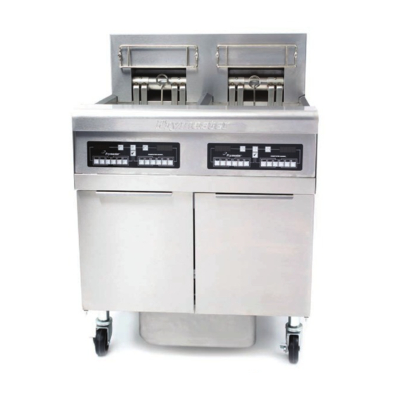
RE SERIES E ELECTRIC FRYERS Tilt Housing Basket Hangers FootPrint Pro Built- in Filtration Unit Filter Pan The appearance of your fryer may differ slightly from that 3–1 ELECTRIC FRYER Elements Top Cap Bezel Power Switch Fuse... -
Page 13: Setup And Shutdown Procedures
3. Ensure that the power is switched on. Some models are equipped with a master switch located behind the fryer door cabinet on the front panel of the component box, next to the fuse. See page 3-1. standby or off is displayed on the computer. -
Page 14: 3.2 Controllers
If this is the first time the fryer is being used after installation, refer to the frypot Boil-Out Procedure on Page 5-2. Refer to the separate Frymaster Fryer Controllers User’s Manual furnished with your fryer for the specific controller operating instructions. -
Page 15: Chapter 4: Filtration Instructions
Frymaster recommends that a Frymaster filter cone holder and filter cone be used when a filter machine is not available. If you are using a Frymaster filter cone holder, be sure that the cone holder rests securely on the metal container. -
Page 16: Preparing The Built-In Filtration System For Use
DO NOT hammer on the drain valve with the cleanout rod or other objects. Damage to the ball inside will result in leaks and will void the Frymaster warranty. 4. After draining the oil, clean all food particles and residual oil from the frypot. BE CAREFUL, this material may still cause severe burns if it comes in contact with bare skin. - Page 17 4.2.1 Preparation for Use with Filter Paper or Filter Pad 1. Pull the filter pan out from the cabinet and remove the crumb tray, hold-down ring, filter paper and filter screen. (See Figure 1) Clean all components with a solution of detergent and hot water, then dry thoroughly.
- Page 18 If using a filter pad, position the hold down ring on top of the pad. DO NOT use filter powder with the pad. 6. Replace the crumb tray in the filter pan, then push the filter pan back into the fryer, positioning it under the drain. 4.2.2 Preparation for Use with the Magnasol Filter Assembly 1.
-
Page 19: Operation Of The Filter
Sprinkle one packet of the Magnasol XL filter powder evenly over the screen. 5. Replace the crumb tray, then push the filter pan back into the fryer, positioning it all the way to the back of the cabinet. - Page 20 6. After the oil is filtered (about 5 minutes), close the drain valve and allow the fryer to refill. Let the filter pump run 10 to 12 seconds after the oil begins to bubble. Turn the filter off.
-
Page 21: Disassembly And Reassembly Of The Magnasol Filter
8. Ensure the drain valve is fully closed. (If the drain valve is not fully closed, the fryer will not operate.) Turn the fryer ON and allow the oil to reach setpoint. The crumb tray in fryers equipped with a filter system must be emptied into a fireproof container at the end of frying operations each day. -
Page 22: Draining And Disposing Of Waste Oil
When your oil has reached the end of its usable life, drain the oil into an appropriate METAL container for transport to the disposal container. Frymaster recommends the use of the Frymaster Shortening Disposal Unit (SDU). NOTE: If using an SDU built before January 2004 the filter pan cover must be removed to allow the unit to be positioned beneath the drain. -
Page 23: Chapter 5: Preventive Maintenance
Clean inside the fryer cabinet with a dry, clean cloth. Wipe all accessible metal surfaces and components to remove accumulated oil and dust. Clean outside the fryer cabinet with a clean, damp cloth soaked with detergent. Wipe with a clean, damp cloth. -
Page 24: Boiling Out The Frypot
Before the fryer is first used, it should be boiled out to ensure that residue from the manufacturing process has been eliminated. Also, after the fryer has been in use for a period of time, a hard film of caramelized oil will form on the inside of the frypot. This film should be periodically removed by following the boil out procedure that follows. -
Page 25: Calibration Of Solid State (Analog) Controller Knob
(7.5 mm) deep into the oil. When the heating elements cycle on for the fourth time, the thermometer should within ±5°F (±2°C) of the temperature control knob setting. 3. If the knob requires adjustment, refer to Chapter 4 of the separate Frymaster Fryer Controllers User’s Manual furnished with your fryer. - Page 26 • Verify that the temperature and high-limit probes are properly connected, tightened and functioning properly, and that mounting hardware and probe guards are present and properly installed. • Verify that component box and contactor box components (i.e. computer/controller, relays, interface boards, transformers, contactors, etc.) are in good condition and free from oil and other debris.
-
Page 27: Chapter 6: Operator Troubleshooting
Although the chapter covers the most common problems reported, you may encounter problems that are not covered. In such instances, the Frymaster Technical Services staff will make every effort to help you identify and resolve the problem. -
Page 28: Troubleshooting
Verify that the drain valve is fully closed. B. If the circuitry in the fryer control system cannot determine the frypot temperature, the system will not allow the... - Page 29 If you are not using solid shortening, the melt-cycle can be cancelled or bypassed. Refer to the separate Frymaster Fryer Controllers User's Manual for the procedure for canceling the melt- cycle for the particular controller installed on your fryer.
- Page 30 FASC. CM III.5 computers may be programmed to display in either Fahrenheit or Celsius. Refer to the separate Frymaster Fryer Controllers User's Manual for instructions on changing the display. Verify that the drain valve is fully closed.
- Page 31 Shut the fryer down and call FASC. The CM III.5 computer may be programmed for constant temperature display or countdown timer display. Refer to the separate Frymaster Fryer Controllers User's Manual for instructions on toggling between these display options.
- Page 32 Corrective Action Digital controllers are manually set to display in one temperature scale or the other. Refer to the separate Frymaster Fryer Controllers User's Manual for instructions on changing the display. Verify that the drain valve is fully closed. If the drain valve is fully...
- Page 33 Filter pump runs but oil does not Test: Close the drain valve and pull return to frypot and the filter pan out from the fryer. there is no bubbling Activate the pump. If bubbling oil occurs, there is a blockage in the oil.
- Page 34 Problem Probable Causes A. Improperly installed filter pan components. Filter pump runs, but oil return is very slow and bubbling oil occurs. B. Attempting to filter with oil that is not hot enough. Corrective Action A. If using filter paper or pad configuration, verify that filter screen is in bottom of pan with paper or pad on top of screen.
- Page 35 THIS PAGE INTENTIONALLY LEFT BLANK...
- Page 36 Frymaster, 8700 Line Avenue, Shreveport, Louisiana 71106 TEL 1-318-865-1711 FAX (Parts) 1-318-688-2200 (Tech Support) 1-318-219-7135 819-6149 SERVICE HOTLINE FEB 09 PRINTED IN THE UNITED STATES 1-800-551-8633...