Table of Contents
Advertisement
Quick Links
Advertisement
Table of Contents

Related Manuals for GRASS VALLEY NV9640


Summary of Contents for GRASS VALLEY NV9640
- Page 1 NV9640 NV9000 Control Panel User’s Guide UG0048-02 19 Nov 2014...
- Page 2 Please read the following terms and conditions carefully. By using NV9640 documentation, you agree to the following terms and conditions. Grass Valley hereby grants permission and license to owners of NV9640 routers to use their product manuals for their own internal business use. Manuals for Grass Valley products may...
- Page 3 Grass Valley offices in Grass Valley, California USA. Software License Agreement and Warranty Information Contact Grass Valley for details on the software license agreement and product warranty. Important Safeguards and Notices This section provides important safety guidelines for operators and service personnel.
- Page 4 The fuse symbol indicates that the fuse referenced in the text must be replaced with one having the ratings indicated. The presence of this symbol in or on Grass Valley equipment means that it has been designed, tested and certified as complying with applicable Underwriter’s Laboratory (USA) regulations and recommendations.
- Page 5 NV9640 User’s Guide General Warnings A warning indicates a possible hazard to personnel which may cause injury or death. Observe the following general warnings when using or working on this equipment: • Heed all warnings on the unit and in the operating instructions.
-
Page 7: Table Of Contents
NV9640 Panel Configuration Page ........ - Page 8 Table of Contents Selection................. . 37 XY Mode —...
- Page 9 The GPIO Section of the NV9640 Page........
- Page 10 NV9640 Specifications........
-
Page 11: Preface
............2 Chapter Structure The following chapters provide detailed information regarding the NV9640 control panel: •... -
Page 12: Terms, Conventions And Abbreviations
Press the SRC 12 button ... The following terms and abbreviations are used throughout this guide: • The term “control panel” refers to the NV9640 control panel and to NV96xx control panels, in general. • “High tally” means that a button is brightly illuminated. -
Page 13: Introduction
4 optically isolated relay outputs and 8 optically isolated inputs: Power Ethernet GPIO (tally) Serial (RS-232) Fig. 2-2: NV9640 Rear 1. An equivalent NV9640V — a GUI that is called a “virtual panel”— is available. It emulates the NV9640. -
Page 14: Panel Organization
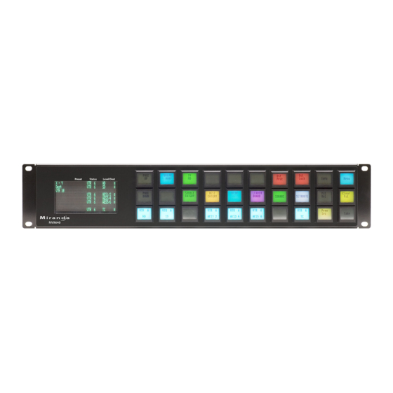
Panel Organization Function Buttons The NV9640 has an array of 30 LCD buttons. Each has 3 lines of text (up to 8 characters per line). The buttons can display one of seven colors dynamically: nominally red, green, blue, purple, amber, yellow, or grey. We say a button is “dark” when its LCD is turned off. -
Page 15: Alphanumeric Display
Operators might need to scroll to see or select a level. In MD mode, the ‘Level/Dest’ column presents all the MD destinations defined in the NV9640 configuration. (Actual destinations are defined in the configuration of the system controller.) Operators might need to scroll to see or select a destination. -
Page 16: Flags
An ‘L’ indicates that a device has been locked. A ‘P’ indicates that a device has been protected. NV9640 operators may lock, protect or release destinations. It is important for operators to know that other operators may lock, protect, or release sources and destinations. -
Page 17: Modes Of Operation
During configuration, you can prescribe NV9640 behavior that depends on the tally inputs. What you connect to the tally interface is, of course, up to you. Grass Valley provides a breakout cable (WC0053) for the tally connector as a purchase option. -
Page 18: Other Nv9640 Functions
Device selection using indexes or suffixes. The NV9640 provides the following additional features: • The NV9640 supports multiple-level breakaways in X-Y mode. This lets you route multiple sources to the same destination on different levels. • The panel supports gang or dub switching in multi-destination mode. -
Page 19: Installation
Depending on your order, the NV9640 items that can ship include: • One or more NV9640 control panels. • One or two power supplies for each NV9640, with straps that secure the AC power cords to the power supplies. • Optional WC0053 breakout cable. -
Page 20: Installation
NV9000 configuration software. You may use the Panel IP Configuration Utility if you want to your NV9640 to have a static IP address or to use DHCP. The panel, as it comes from the factory, defaults to DHCP. -
Page 21: Initialization
Follow these steps for each NV9640 you are installing: 1 Power up the NV9640. Do not connect its Ethernet cable. (Disconnect it if it is connected.) After a few seconds, the alphanumeric display will show ‘Acquire IP Address’ at the top and show the panel’s current panel ID. -
Page 22: Testing
Installation Testing Testing As shown above in step 3, a panel test function is available when the NV9640 is disconnected from the system controller. Run the test to determine the health of your NV9640. See Setup Mode on page 71 for detail. Press the ‘Software Versions’ button to review the versions of installed software and firmware. -
Page 23: Configuration
The NV9640, in addition, has an 8×42 alphanumeric display that presents the status of opera- tions as they occur. An NV9640 panel should be configured with at least one ‘Page Up’ button and at least one ‘Page Down’ button with which the operator can scroll the display. - Page 24 Choose “NV9640” from the ‘Type’ field. In the ID field, enter the panel ID you assigned to the panel while it was in setup mode. Give a name to the panel in the name field and select a user.
- Page 25 Global Navigation on page 40. Return to the ‘Control Panels’ page to view your new entry. To edit an NV9640 configuration, either double-click its list entry or select the entry with a check in the checkbox and then click ‘Edit Selected Control Panels’: You will then see the panel configuration page for the selected NV9640.
-
Page 26: Nv9640 Panel Configuration Page
Page Table GPIO Defi- nitions Fig. 4-1: NV9640 Configuration Page (Default) Similar pages exist for NV9640 suffix templates and for global navigation templates. See Global Navigation on page 40. After you configure buttons, and button pages, the appearance of the panel buttons will have changed. -
Page 27: Regions Of The Configuration Page
In this section, configurers may specify the behavioral characteristics of the panel. Configuration Tasks The person configuring an NV9640 panel will want to consider how best to use the hierarchical nature of the button tree to support the devices and routers in the router control system at hand. -
Page 28: Commitment Buttons
In particular, the operator, having navigated down a subtree, must have some way to navi- gate back up the subtree. There are several ways to ensure this. Two are listed here: • Place a “Back” button on each subpage. The “back” button causes the NV9640 to redisplay the previous page. •... -
Page 29: Panel Options
Your configuration should have at least one ‘Page Up’ and ‘Page Down’ button if you wish to do this. A double-click is required. It is assumed that the configura- tion loaded in the NV9640 and available to operators will have the same ‘Page Up’ and ‘Page Down’ buttons. - Page 30 Configuration Panel Options XY Data Automatic If a machine control (i.e., data) level is involved in a route, the sys- Routing Mode tem makes the route on the control level even if the control port is in use on the source or destination device. It breaks the previous control connection and then makes a new control connection for the route in progress.
-
Page 31: Checkbox Options
NV9640 User’s Guide Default Name System Name A list of “name sets” appears in the drop-down menu. The name sets can be defined under the System Management pane of NV9000-SE Utilities. Choose ‘System Name’ in this list if you do not want, or do not care about, device name aliases. - Page 32 After selecting many MD destinations (with ‘Hold’ mode on), it can be time-consuming and error-prone to find them all (and no others) to deselect them after a take. When you enable this option, the NV9640 does exactly that (and turns off hold mode). •...
-
Page 33: Button Definitions
The set of devices in a cate- gory can change over time (as the configuration database changes); the NV9640 device list changes also. The number and names of categories can also change over time and the NV9640 will track those changes too. -
Page 34: Button Specification
Configuration Button Definitions When a device list appears on the panel, the system lights the ‘up’ button so the operator can easily return to the page containing the category button. Note Certain button fields contain a colon (:) and number after the data in the field. The number is the record ID of the object in the NV9000 configuration database. -
Page 35: Button Types
Note that different subsets of these button types are available when you are defining a global suffix template or a global navigation template. See Global Navigation on page 40. These are the button types available for NV9640 configurations: Type Description Back The ‘Back’... - Page 36 Configuration Button Definitions Type Description Category Displays a category’s device list. When you assign a category button, two additional drop-down menus appear: ‘Src Category’ and ‘Dst Category’ . Choose a category from one of the category lists. When you choose a source category, the destination categories become inaccessible and vice versa: a category button must be either a source category or a destination category.
- Page 37 Menu This button puts the NV9640 panel in menu mode and displays a menu on the LCD buttons that provides access to a variety of panel options. The button is required if you want the user to have access to the menu.
- Page 38 Configuration Button Definitions Type Description Navigate During operation, a navigate button selects and displays a “target” button page. During configuration, a navigate button presents a dialog in which you can enter details of the target page. After you do so, SE displays the target page’s buttons on the panel image and adds the subtree to the tree window in the lower left corner if it is not there.
- Page 39 NV9640 User’s Guide Type Description Salvo Executes a salvo. When you assign a Salvo button, a drop-down list appears in which you select a system salvo. The ‘None’ entry is merely a placeholder. Do not choose ‘None’ . (You can generate salvo buttons automatically in the ‘Edit Navigation Button’...
- Page 40 A source/destination button selects both a source and a destination at one time. Destination Source/destination buttons can be configured to perform immediate takes. (It is a NV9640 panel option.) If they are not so configured, the operator must also press a ‘Take’ button to effect a take. Take In X-Y mode, a take button switches the preset source device to the selected destination device on selected levels.
-
Page 41: Edit Navigation Button' Dialog
NV9640 User’s Guide Type Description Virtual Level In X-Y mode, this button causes the alphanumeric display to show virtual levels Expand at the lowest level of grouping (with the most detail). The button affects only virtual levels that have been grouped. See Level Grouping on page 52. - Page 42 This option creates a new page in the button tree. During operation, the navigation button you are creating will cause the NV9640 to display, or jump to, that page. The name of the page and the button caption are what you type in the three lines for the button caption. You can change the name of the page in the button page list.
-
Page 43: Automatic Fill Options
NV9640 User’s Guide Automatic Fill Options • Source Devices SE assigns sources to buttons in new button subpage(s). If it has too many sources to fit on the subpage, it creates further subpages as needed. The software adds ‘Back’ and ‘Forward’... -
Page 44: Button Page List
Configuration Button Page List Categories that are both source and destination categories are included. • Destination Categories Automatic fill using destination categories is the same as for source categories, except that destination categories are chosen. • Manually Order Buttons If you check the ‘Manually order buttons’ box, SE presents a dialog that lists the sources, des- tinations, categories, or salvos you selected. -
Page 45: Tally (Gpio) Window
It has two sections: inputs and outputs. By clicking on one of the input or output buttons, you can configure the input or output. (The NV9640 has no actual tally buttons. These buttons represent the DB25 connector at the rear. The buttons are present in the configuration page to allow you to configure the tally interface.) -
Page 46: Selection Button Behavior
Configuration Selection Buttons Operators can scroll through multiple pages of levels in X-Y mode and through multiple pages of devices in MD mode. There are 3 options for scrolling: 1 Scrolling the display only. The items on the selection buttons do not scroll. When an operator scrolls the display only, it scrolls by 8 lines at a time. -
Page 47: Selection
NV9640 User’s Guide Selection XY Mode — Normal When the operator selects a destination, all selection buttons that have levels defined for the destination turn on (high-tally). The operator may select or deselect any levels as required, by pressing selection buttons and perhaps scrolling the display. -
Page 48: Single-Destination Mode
Configuration Single-Destination Mode Unless you will always have fewer than 8 levels defined and 8 or fewer MD destinations defined, it is advisable to place exactly 8 selection buttons on your button page. It is obvi- ously advisable to position the selection buttons in order on the button page. ... -
Page 49: How To Configure Md Destinations
NV9640 User’s Guide The limit to the number of MD devices is controlled by a panel option. If the limit is 64, for example, the display can scroll through 8 pages of 8 rows, regardless of whether these rows have been assigned a destination. -
Page 50: Md Destination Options
A suffix template is a single page only. The buttons allowed in a suffix template are a small subset of the buttons supported by NV9640 configurations. Navigate templates support all functions except ‘Global Navigate’ . That is because templates cannot be nested. -
Page 51: Names
NV9640 User’s Guide Names After adding global navigation templates to your N9000 configuration, you will see them identi- fied as such in the control panel list: Navigation Template Suffix Tem- plate The words “Navigate” and “Suffix” appear in the ‘Panel Type’ and ‘Configuration Name’ columns. -
Page 52: Referencing A Navigate Template
Configuration Global Navigation The suffix page is a copy of the suffix template. It is not the template or a link to the template. Category buttons in the panel configuration that reference a suffix template do have links to their templates. ... -
Page 53: Composing Suffix Templates
‘Push changes to panel configs’ . When you do, the configuration software adjusts all NV9640 panel configurations to use the modified suffix template. This might override changes you have made to the copy of the suffix page in some panel configuration. -
Page 54: Composing Navigate Templates
Configuration Global Navigation If you make a change to a suffix template and it is in use by one or more panel configurations, you will want to click ‘Push changes to panel configs’ . You can see the panel configurations in the list under ‘Panel References’: List of panel configuration pages that use this suffix tem-... - Page 55 NV9640 User’s Guide When you click ‘Push changes to panel configs’ , the configuration software adjusts all panel configurations to use the modified navigate template. If you want to update the global navigation page in only some of your panels, create an alter- nate version of your navigate template and change the panel configurations to use one or the other as desired.
- Page 56 Configuration Global Navigation...
-
Page 57: Operation
This chapter is intended specifically for the NV9640 panel operator. Summary As an NV9640 operator, you will be confronted initially with a relatively small panel — 30 buttons of various colors and a small alphanumeric display. Because the NV9640 is a “hierarchical”... -
Page 58: Modes Of Operation
• Setup mode — where the NV9640 is freshly powered up, but disconnected from the network. In this mode, the configurer can preset the NV9640’s panel ID and perform a few diagnostic tasks. Usually, only configurers need be concerned with setup mode. -
Page 59: Levels
NV9640 User’s Guide Buttons are also color-coded. The colors are specified in the NV9640 configuration. In most cases, buttons that are high-tally (bright) are active or selected. Buttons that are low-tally (muted) are inactive or unselected. Buttons that are dark either have no function or are momen- tarily disabled. -
Page 60: Level Mapping
Operation Summary The top line of text identifies the current source and should be identical to the matching entry in the ‘Status’ column of the display. The middle line identifies the preset source and should be identical to the matching entry in the ‘Preset’ column of the display. If there is no ‘Take’ pending, the preset fields will be blank, both in the display and on the buttons. -
Page 61: Lists
Lists The NV9640 can produce lists of devices, categories, and salvos automatically — on the buttons. Lists of categories and salvos are generated statically — during configuration. Lists of sources and destinations can be generated dynamically —... -
Page 62: Breakaway
The levels ‘Video’ and ‘Audio’ are abstract levels; the other levels are basic levels. The NV9640, at present, ignores the concept of level groups, and presents any configured level groups as completely expanded. That is, it always displays basic levels and never abstract levels. -
Page 63: Buttons
CAM and the cameras in the category might be named CAM1, CAM2, and so on. NV9640 category buttons can represent either a source category or a destination category (but not both). When you pressing category buttons to begin device selection, one of two things occurs: •... -
Page 64: Back
When you press a category button, the NV9640 displays the first of perhaps several pages of device buttons. You can scroll the pages using back and forward buttons. If you press ‘Back’ while on the first page of the list, the NV9640 returns to the page containing the category button. -
Page 65: Chop
Suffix Page When you press a category button, the NV9640 displays a suffix page which will contain buttons forming a numeric keypad, other buttons that represent alphanumeric suffixes and perhaps a few other buttons. Use the keypad to enter an index or suffixes of a device within the category. If you make a mistake, press the ‘Clear Preset’... -
Page 66: Destination
Operation Operating Concepts The default button text is “Default State” but the button can have any legend. Destination This button selects a destination. A destination button can occur on any page, but destination buttons often appear in destina- tion lists. Destination lists can occur either (1) in automatically configured, but static, pages or (2) as a result of pressing a destination category button, in which case, the destinations buttons are generated dynamically. -
Page 67: Free Source
NV9640 User’s Guide Note: a protect prevents others from routing to a destination; a lock prevents anyone — even the user who issued the lock — from routing to the destination. You may lock a protected destination, but you cannot change a locked destination to a protected destination directly. -
Page 68: Information
Operation Operating Concepts MD Mode In MD mode, turning hold mode on allows you to select more than one destination button at a time. When you select a source, the source applies to all selected (high-tally) destinations. If hold is still on when you press ‘Take’ , the selected destinations remain selected and the display reflects the selected destinations. -
Page 69: Menu
The default button text is “Level Map” but the button can have any legend. Menu The button puts the NV9640 panel in menu mode and places a small menu on the LCD buttons, that provides access to a variety of panel options. -
Page 70: Name Set Toggle
Operation Operating Concepts Name Set Toggle A ‘Name Set Toggle’ button toggles the panel between its default name set and the “system name” set. Whichever name set you select becomes the “active” name set. ‘Name Set Toggle’ buttons are disabled while a category selection is in progress. ... -
Page 71: Panel Lock
‘Preset Release’ button and tell you who locked or protected the source. You can release it if your panel has “forced release” enabled. (Note that you cannot lock or protect sources with the NV9640.) Press the ‘Preset Release’ button to release the source. -
Page 72: Quick Source
Operation Operating Concepts Quick Source A quick source button selects a source and performs an immediate take. Quick source and source buttons are similar, except that the quick source performs a take. Be aware of which buttons are quick sources so you do not perform an accidental take. Normally, the button text is the source’s mnemonic, but the configurer can assign any text to the button. -
Page 73: Source
NV9640 User’s Guide When you scroll the display using the ‘Page Up’ or ‘Page Down’ buttons, the legends on the selection buttons change to match the display. X-Y Mode When the panel is in X-Y mode, a selection button represents a virtual level present on the alphanumeric display. -
Page 74: Source/Destination
Operation Operating Concepts Normally, the button text is the source device’s mnemonic, but the configurer can assign any text to the button. Preset Release on page 61 and Destination on page 56. Source/Destination A source/destination button selects both a source and a destination and optionally performs an immediate take. -
Page 75: Virtual Level Expander
Release To remove a lock or protect. Some control panels can lock or protect both sources and destinations. However, The NV9640 provides locks and protects for destinations only. A forced release is when the lock or protect is removed by someone other than the owner. A forced release can be performed: •... -
Page 76: Takes
Operation Operating Concepts Takes Following are brief instructions on how to perform a take in 3 scenarios. XY Mode 1 If required, enter X-Y mode. (Use the XY/MD button.) 2 If required, select a destination. 3 Optionally choose levels. 4 Select a source and press ‘Take’ . 5 Select a quick source. -
Page 77: Broadcast Routes
NV9640 User’s Guide 1 Switch to destination mode if necessary. 2 Press a VTR category button. (Suffix buttons become enabled.) 3 Press 4, then 2. The device is selected, but the name appearing in the destination display is “PROD_A. ”... -
Page 78: Automatic Data Routing
Operation Operating Concepts Automatic Data Routing A take involving a machine control level occurs naturally on all selected levels, including the machine control level, regardless of whether an affected machine control port is in use. The system breaks any existing control connections involved with the source and destination and makes a new control connection for the source and destination. -
Page 79: Salvo Mode
The NV9640’s display tells you the name of the salvo and instructs you to press the take button to execute the salvo. If you wish to cancel the salvo before it executes, press the salvo button again. -
Page 80: Software Versions
O5 O5 • • • The 3 buttons on the left tell you the current versions of the software in the NV9640. Generally, this is of no relevance unless you are in a diagnostic situation. Press ‘Exit’ on the right to return to the menu. -
Page 81: Lcd Control
87 for a color chart. Setup Mode Setup mode occurs when the NV9640 is disconnected from its network and is freshly powered up. In setup mode, you can set or change the panel ID, determine software versions, and perform a test of the panel’s buttons. It is in setup mode that you must initially set the panel ID. - Page 82 Operation Setup Mode In this illustration, the panel ID was already set to 6412. The “Acquire IP Address” is a status message during initialization. Until you connect the panel to its network, the status message will remain the same. Press the ‘Menu’ button at the far right to access the setup menu: PANEL PANEL SOFTWARE...
- Page 83 NV9640 User’s Guide Each time you press the button, the panel illuminates all its LCD buttons in a single color, changing the color each time you press the button. Keep pressing the button until all 7 col- ors (high and low tally) have been displayed and ‘Button Number’ appears on the left but-...
- Page 84 Operation Setup Mode...
-
Page 85: Gpio
The tally interface includes 8 optically isolated inputs and 4 solid-state relay outputs (also opti- cally isolated). Tally devices you connect to inputs can trigger events — through the NV9640 — in the router control system. The router control system can trigger events that — through the relays in the NV9640 —... -
Page 86: Output
Optional Grounding Fig. 6-3: GPI Output When a condition (defined for the relay) occurs, the router control system notifies the NV9640 which then opens or closes the relay. The relay switches the customer’s circuit on or off. (It does not power the circuit. Customers must provide their own power.) GPIO Configuration Concepts These are the I/O characteristics of the NV9640’s tally interface:... -
Page 87: Configuring Outputs
NV9640 User’s Guide Configuring Outputs Clicking an output button (one of 4) displays a “Relay Rule” dialog for the output: term term term operator operator Fig. 6-4: Relay Rule Dialog In this dialog, you create a Boolean expression involving sources destinations, port status, and GPI (input) status. - Page 88 The actual logic takes place in the router control system, based on the state of the NV9640 inputs and other system-wide events. The router control system sends signals to the NV9640 instructing it to open or close its relays.
-
Page 89: Configuring Inputs
Its 8 inputs can be switched on or off by your external devices. When an input transitions on or off, the NV9640 can respond with one of 4 actions, such as executing a salvo. (It is the system that actually executes the salvo.) - Page 90 GPIO Configuring Inputs...
-
Page 91: Technical Details
Technical Details Chapter 7 provides electrical and mechanical specifications for the NV9640. Topics Power Specifications ..............81 NV9640 Specifications . -
Page 92: Nv9640 Specifications
DC Output Fig. 7-1: The power output has Molex 4-pin plug. See Power Cord Retention on page 88. NV9640 Specifications NV9640 Physical Specifications Specification Detail Dimensions Height: 3.47 in (88.1 mm), fits EIA 2 RU (3.5 in or 88.9 mm), Width: 19.0 in (482.6 mm). -
Page 93: Environmental Specifications
Buttons: high-tally is maximum brightness; low-tally is low brightness. Configuration Page The initial button page for a new NV9640 configuration has one sub-page (“Breakaway”), a ‘Take’ button, ‘Page Up’ and ‘Page Down’ buttons, and two other buttons. The “breakaway” button is a navigation button that displays a page of selection buttons. -
Page 94: Dhcp
Technical Details Drawings DHCP The panel is set up to respond to DHCP from the factory. It is possible to assign the panel a fixed IP address using the Panel IP Configuration Utility. Drawings The drawings on the following pages identify features and provide overall and critical dimensions. - Page 95 NV9640 User’s Guide Fig. 7-2: Front and Top Views of the NV9640...
- Page 96 Technical Details Drawings Fig. 7-3: Rear and Top Views of the NV9640...
-
Page 97: Misc. Topics
Misc. Topics Chapter 8 provides the following. Topics LCD Buttons ................87 Power Cord Retention . -
Page 98: Power Cord Retention
Misc. Topics Power Cord Retention Power Cord Retention Use the supplied retention strap to keep the AC power cord firmly connected to the power supply. Follow these steps to use the strap: 1 Firmly insert the AC power cord into the power supply. Examine the last figure in this section to see how the strap should be applied. -
Page 99: Ordering Information
NV9640 User’s Guide Ordering Information These are the NV9640 components: PS0001 12V power supply, 4-pin Molex connector, with cord, and cord retention strap. NV9640 NV9000 control panel. 30 button, 2RU, XY/MD, hierarchical. WC0053 Optional breakout cable for the tally interface... - Page 100 Misc. Topics Ordering Information...
-
Page 101: Glossary
8 of the time code router. GPIO General Purpose Input and Output. A generic term for the NV9640’s tally interface. The tally interface is called the “GPI Interface” at the rear of the NV9640. - Page 102 Glossary A device can be both a source and destination. An example of such a device is a VTR. System The system administrator is the person responsible for installing, configuring, and maintaining a administrator router control system. Tally (1) High or low button illumination. (2) Tally interface to be defined.
-
Page 103: Index
Index Button add control panel ....... .14 back ..4–5, 18, 25, 32–33, 51, 53–54, 56–57, 60 Acquiring IP address (message) . - Page 104 NV9640 ........
- Page 105 Device lists ....... 23, 28, 53–54 NV9640, rear view ....... .86 Devices NV9640, rear, photo .
- Page 106 ......9 Installation, NV9640 ........9 IP address .
- Page 107 NV9640 ........9–10, 13, 89...
- Page 108 NV9640, front ........3...
- Page 109 Undefined (button) ......17, 30, 64 environmental, NV9640 ......83 UniConfig .
- Page 110 Index...
-
Page 111: Contact Us
Contact Us Grass Valley Technical Support For technical assistance, please contact the Grass Valley Technical Support center nearest you: Americas Asia Office hours: 9:00 a.m. – 9:00 p.m. (EST) Office hours: 9:30 a.m. – 6:00 p.m. (GMT+8) Telephone: +1-800-547-8949 Telephone:...