
Related Manuals for Milwaukee MW306 MAX


Summary of Contents for Milwaukee MW306 MAX
- Page 1 INSTRUCTION MANUAL EC / TDS / NaCl / Temperature Portable Meter SATISFACTION GUARANTEED...
- Page 2 This instruction manual will provide you the necessary information for correct use of the meter. All rights are reserved. Reproduction in whole or in part is prohibited without the written consent of the copyright owner, Milwaukee Instruments Inc., Rocky Mount, NC 27804 USA.
-
Page 3: Table Of Contents
TABLE OF CONTENTS 1. PRELIMINARY EXAMINATION ................4 2. INSTRUMENT OVERVIEW ..................5 3. SPECIFICATIONS ......................6 4. FUNCTIONAL & DISPLAY DESCRIPTION ............8 5. MA815D/1 PROBE DESCRIPTION ...............11 6. GENERAL OPERATIONS ..................12 6.1. BATTERY MANAGEMENT & REPLACEMENT ........12 6.2. CONNECTING THE PROBE................13 6.3. ELECTRODE CARE & MAINTENANCE ..........13 7. -
Page 4: Preliminary Examination
4 MW Portable Meter 1. PRELIMINARY EXAMINATION MW306 portable meter is delivered in a rugged carrying case and is supplied with: y MA815D/1 4-ring EC / TDS / NaCl / Temperature probe with DIN connector and 1 meter (3.2 feet) cable y 1.5V alkaline AA battery (3 pcs.) y Micro USB cable y Instrument quality certificate... -
Page 5: Instrument Overview 5
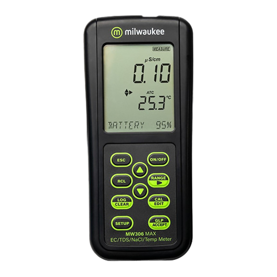
INSTRUMENT OVERVIEW 5 2. INSTRUMENT OVERVIEW MW306 is a portable water-resistant meter that can measure up to four di erent parameters – EC, TDS, salinity (in PSU, g/L, percentage NaCl and temperature. y Easy to read LCD display y Auto-o feature to prolong battery life y All measurements can be temperature compensated automatically (ATC), or manually (MTC) with a user-selectable compensation coe icient. -
Page 6: Specifications
6 MW Portable Meter 3. SPECIFICATIONS 0.00 to 29.99 S/cm 30.0 to 299.9 S/cm 300 to 2999 S/cm 3.00 to 29.99 mS/cm 30.0 to 200.0 mS/cm up to 500.0 mS/cm, absolute conductivity ** 0.00 to 14.99 ppm (mg/L) 15.0 to 149.9 ppm (mg/L) 150 to 1499 ppm (mg/L) Range * TDS (with... - Page 7 SPECIFICATIONS 7 Single cell factor calibration 6 standards: EC / TDS 84 S/cm, 1413 S/cm, 5.00 mS/cm, 12.88 mS/cm, 80.0 mS/cm, 111.8 mS/cm Calibration One-point o set: 0.00 S/cm One-point Salinity with MA9066 Salinity calibration solution Temp. No temperature calibration ATC –...
-
Page 8: Functional & Display Description
8 MW Portable Meter 4. FUNCTIONAL & DISPLAY DESCRIPTION Front Panel 1. Liquid Crystal Display (LCD) 2. ESC key, to exit current mode 3. RCL key, to recall the logged values 4. LOG/CLEAR key, to log the reading or to clear calibration or logging 5. - Page 9 FUNCTIONAL & DISPLAY DESCRIPTION 9 Top Panel 1. Micro USB port 2. Micro USB port cap 3. DIN probe connector...
- Page 10 10 MW Portable Meter Display Description 1. Mode tags 2. Battery status 3. Stability indicator 4. USB connection status 5. Arrow tags, to navigate the menu in either direction 6. Probe symbol 7. Log tag 8. Accept tag 9. Third LCD line, message area 10.
-
Page 11: Ma815D/1 Probe Description 11
MA815D/1 PROBE DESCRIPTION 11 5. MA815D/1 PROBE DESCRIPTION Main features: y Direct signal processing for noise-free measurements y Accurate and integrated temperature measurement 1. O-ring 2. Plastic insulator 3. Steel rings 4. Probe sleeve... -
Page 12: General Operations
12 MW Portable Meter 6. GENERAL OPERATIONS 6.1. BATTERY MANAGEMENT & REPLACEMENT The meters are supplied with 3 x 1.5V alkaline AA batteries and equipped with Battery Error Prevention System (BEPS) feature, which turns the meter o after 10 minutes of non-use (see SETUP OPTIONS, Auto O section). -
Page 13: Connecting The Probe
GENERAL OPERATIONS 13 6.2. CONNECTING THE PROBE MA815D/1 is connected to the meter through a DIN connector, making attaching and removing the probe an easy process. y With the meter o , connect the probe to the DIN socket on the top of the meter. -
Page 14: Setup
14 MW Portable Meter 7. SETUP To configure the meter settings, modify default values or set measurement parameters: y Press SETUP to enter (or exit) Setup mode y Use keys to navigate the menus (view parameters) y Press CAL/EDIT to enter Edit mode (modify parameters) y Press RANGE/... - Page 15 SETUP 15 Calibration Expired Warning Options: 1 to 7 days (default) or o Use keys to select the number of days since last calibration has elapsed. Temperature Compensation Options: ATC (default), MTC or NO TC With the probe connected, press RANGE/ to select options. EC Cell Factor Options: 0.010 (default) to 9.999 With the probe connected, use ...
- Page 16 16 MW Portable Meter EC Temperature Coe icient (T.Coef.) Options: 0.00 to 6.00 (1.90 default) With the probe connected, use keys to change the value. EC Temperature Reference (T.Ref.) Options: 25 °C (default) and 20 °C With the probe connected, use keys to change the value. TDS Factor Options: 0.40 to 0.80 (0.50 default) With the probe connected, use ...
- Page 17 SETUP 17 EC Range Options: AUTO (default), 29.99 S/cm, 299.9 S/cm, 2999 S/cm, 29.99 mS/cm, 200.0 mS/cm Note: Absolute conductivity — up to 500.0 mS/cm — is the conductivity value without temperature compensation. With the probe connected, use keys to change the value. When autoranging, the meter automatically chooses the optimum conductivity range to maintain the highest possible accuracy.
- Page 18 18 MW Portable Meter Note: Selected TDS range is active during measurements only. If exceeded, the full-scale value is displayed blinking. Logged data is displayed in mg/L in the CSV files. TDS Unit Options: ppm (mg/L) default and g/L With the probe connected, press RANGE/ to select options. Salinity Scale Options: NaCl% (default), psu and g/L With the probe connected, press RANGE/...
- Page 19 SETUP 19 Date Options: year, month or day Press RANGE/ to select. Use keys to modify the values. Time Options: hour, minute or second Press RANGE/ to select. Use keys to modify the values. Auto O Options: 5, 10 (default), 30, 60 minutes or o Use ...
- Page 20 20 MW Portable Meter Sound Options: enable (default) or disable Use keys to select. When pressed, each key will emit a short acoustic signal. Temperature Unit Options: °C (default) or °F Use keys to select the unit. LCD Contrast Options: 1 to 9 (default) Use ...
- Page 21 SETUP 21 Default Values Resets meter settings to factory defaults. Press GLP/ACCEPT to restore the default values. “RESET DONE” message confirms that the meter performs with default settings. Instrument Firmware Version Displays the installed firmware version. Meter ID / Serial Number Use ...
- Page 22 22 MW Portable Meter Separator Type Option: comma (default) or semicolon Use keys to select the columns separator for the CSV file. Export to PC / Log on Meter Options: Export to PC and Log on Meter With the micro USB cable connected, press SETUP. Press CAL/EDIT to enter Edit mode.
-
Page 23: Ec / Tds
EC / TDS 23 8. EC / TDS 8.1. PREPARATION Pour small quantities of conductivity calibration solution into clean beakers. To minimize cross-contamination, use two beakers: one for rinsing the probe and the other for calibration. Note: At power on the meter starts measuring with the previously selected range (conductivity, TDS or salinity). - Page 24 24 MW Portable Meter Zero Calibration For zero calibration, to correct readings around 0.00 S/cm, keep the dry probe in the air. The slope is evaluated when the calibration is performed in any other point. One-Point Calibration 1. Place the probe in the calibration solution making sure that the sleeve holes are completely submersed.
- Page 25 EC / TDS 25 5. Press GLP/ACCEPT key to confirm calibration. The instrument displays “SAVING”, stores the calibration values and returns to measurement mode. Note: The TDS reading is automatically derived from the EC reading and no calibration is needed. Manual Calibration This option may be used to perform a manual calibration in a custom standard, i.e.
-
Page 26: Measurement
26 MW Portable Meter 8.3. MEASUREMENT Conductivity Measurement When connected, the MA815D/1 probe is automatically recognized. Place the calibrated probe in the sample, making sure that the sleeve holes are completely submerged. Tap the probe to remove any air bubbles that may be trapped inside the sleeve. To change to EC mode, press RANGE/. - Page 27 EC / TDS 27 Use the keys to view the current temperature coe icient. The value is displayed along with the Cell Factor (C.F.) on the third LCD line. To change the temperature coe icient, see SETUP section for details. A temperature coe icient must also be set for the sample.
-
Page 28: Warnings & Messages
28 MW Portable Meter To toggle between information displayed on the third LCD line, use the keys. y If the reading is out of range, the full-scale value is displayed blinking. 8.4. WARNINGS & MESSAGES Messages Displayed During Calibration y If the reading exceeds expected value, “WRONG STANDARD”... - Page 29 EC / TDS 29 Messages Displayed During Measurement y If the EC measurement exceeds the specified limits or the temperature exceeds (-20 to 120°C), “OUT OF SPEC” message is displayed on the third LCD line. y If the EC measurement exceeds the user-selected range the “OVER RANGE”...
-
Page 30: Salinity
30 MW Portable Meter 9. SALINITY 9.1. PREPARATION Pour small quantities of MA9066 salinity calibration solution into clean beakers. To minimize cross-contamination, use two beakers: one for rinsing the probe and the other for calibration. Note: When the meter is switched on, it starts measuring with the previously selected range (conductivity, TDS or salinity). -
Page 31: Measurement
SALINITY 31 9.3. MEASUREMENT MW306 supports three seawater salinity scales: y Practical Salinity Units (PSU) y Natural Seawater (g/L) y Percentage (%NaCl) Press RANGE/ to select salinity scales. Verify that the required scale is configured in SETUP. Note: These units are for determining salinity and they refer to general use of saltwater. - Page 32 32 MW Portable Meter where: ratio of sample conductivity to standard conductivity at Temperature = (T) °C (sample) uncompensated conductivity at T °C the corresponding conductivity of C (35, 15) = 42.914 mS/cm KCI solution containing a mass of 32.4356 g KCl/1 Kg solution temperature compensation polynomial = 0.008 = 0.0005...
-
Page 33: Warnings & Messages
SALINITY 33 9.4. WARNINGS & MESSAGES Messages Displayed During Calibration y If an EC calibration is performed, the %NaCl calibration is automatically cleared. A new %NaCl calibration is required. y If the reading exceeds expected calibration standard, “WRONG STANDARD” message is displayed and calibration can not be confirmed. - Page 34 34 MW Portable Meter y If a %NaCl calibration is required, “NO CAL” message is displayed. y If Calibration Expired Warning is on and the number of days set have passed, or an EC calibration was performed (clearing the %NaCl calibration), the “CAL EXPIRED” message is displayed. y If no probe is connected, “NO PROBE”...
-
Page 35: Logging
LOGGING 35 10. LOGGING MW306 supports three types of logging: manual log on demand, log on stability and interval logging. See Log Type in SETUP OPTIONS section. The meter can hold up to 1000 log records. Up to 200 for manual log on demand, up to 200 for log on stability and up to 1000 for interval logging. - Page 36 36 MW Portable Meter Manual Log on Demand 1. From the Setup mode, set Log Type to MANUAL. 2. From the measurement screen press LOG/CLEAR. LCD displays “PLEASE WAIT”. The LOG ### “SAVED” screen displays stored log number. "FREE" ### screen displays the number of available records.
- Page 37 LOGGING 37 Interval Logging 1. From the Setup mode, set Log Type to INTERVAL (default) and desired time interval. 2. From the measurement screen press LOG/CLEAR. LCD displays “PLEASE WAIT”. The LOG ### LOT ### screen displays on third LCD line the measurement log number (bottom left) and interval logging session lot number (bottom right).
-
Page 38: Data Management
38 MW Portable Meter 10.2. DATA MANAGEMENT y A lot contains 1 to 600 log records (saved measurement data) y Maximum number of lots that can be stored is 100, excluding Manual and Stability y Maximum number of log records that can be stored is 1000, across all lots y Manual and Stability logs can store up to 200 records (each) y Interval logging sessions (across all 100 lots) can store up to... - Page 39 LOGGING 39 6. Press RANGE/ to view, additional log data: date, time, cell factor, temperature coe icient, temperature reference, displayed on the third LCD line. 10.2.2. Deleting Data Manual Log on Demand & Stability Log 1. Press RCL to access the logged data. LCD displays “PLEASE WAIT”...
- Page 40 40 MW Portable Meter Individual Logs / Records 1. Press RCL to access the logged data. LCD displays “PLEASE WAIT” followed by “LOG RECALL” with ACCEPT tag blinking and the total number of logs. 2. Press GLP/ACCEPT to confirm. 3. Use keys to select MANUAL or STABILITY lot type. 4.
- Page 41 LOGGING 41 6. Press GLP/ACCEPT to confirm (to exit, press ESC or CAL/EDIT or LOG/CLEAR). “PLEASE WAIT” with ACCEPT tag blinking is displayed, until the lot is deleted. After the lot has been deleted “CLEAR DONE” message displays briefly. Display shows the previous lot ###. Delete All 1.
- Page 42 42 MW Portable Meter 10.2.3. Exporting Data PC Export 1. With the meter on, use the supplied micro USB cable to connect to a PC. 2. Press SETUP then CAL/EDIT. 3. Use the keys and select “EXPORT TO PC”. The meter is detected as a removable drive.
- Page 43 LOGGING 43 2. Press RCL then RANGE/ to select the “EXPORT ALL” option. 3. Press GLP/ACCEPT to confirm. LCD displays "EXPORTING" and the percentage counter, followed by "DONE" when export is completed. Display returns to the lot selection screen. Note: The USB drive can be safely removed if the USB icon is not displayed.
- Page 44 44 MW Portable Meter Overwriting existing data. 1. When the LCD displays "EXPORT" with ACCEPT and lot number blinking (USB icon displayed), an identical named lot exists on the USB drive. 2. Press GLP/ACCEPT to continue. LCD displays "OVERWRITE" with ACCEPT tag blinking. 3.
-
Page 45: Glp 45
GLP 45 11. GLP Good Laboratory Practice (GLP) allows the user to store and recall calibration data. Correlating readings with specific calibrations ensures uniformity and consistency. Calibration data is stored automatically after a successful calibration. A new EC calibration automatically clears the %NaCl calibration. -
Page 46: Troubleshooting
Check the keyboard. If LCD tags displayed ON/OFF key is error persists, contact continuously at blocked Milwaukee Technical startup Service. “Internal Er X” Internal error Restart the meter. message If error persists, contact Milwaukee Technical... -
Page 47: Accessories
ACCESSORIES 47 13. ACCESSORIES 4-ring EC / TDS / NaCl / Temperature probe MA815D/1 with DIN connector MA9060 12880 S/cm Calibration solution (230 ml) MA9061 1413 S/cm Calibration solution (230 ml) MA9063 84 S/cm Calibration solution (230 ml) MA9064 80000 S/cm Calibration solution (230 ml) MA9065 111.8 mS/cm Calibration solution (230 ml) MA9066... -
Page 48: Certification
48 MW Portable Meter CERTIFICATION Milwaukee Instruments conform to the CE European Directives. Disposal of Electrical & Electronic Equipment. Do not treat this product as household waste. Hand it over to the appropriate collection point for the recycling of electrical and electronic equipment. -
Page 49: Warranty
Damage due to accidents, misuse, tampering or lack of prescribed maintenance is not covered by warranty. If service is required, contact your local Milwaukee Instruments Technical Service. If the repair is not covered by the warranty, you will be notified of the charges incurred. - Page 51 Milwaukee Instruments reserves the right to make improvements in design, construction and appearance of its products without advance notice.
- Page 52 THANK YOU FOR CHOOSING Sales and Technical Service Contacts: Milwaukee Electronics Kft. Alsó-kikötő sor 11C H-6726 Szeged - HUNGARY tel: +36 62 428 050 fax: +36 62 428 051 www.milwaukeeinst.com e-mail: sales@milwaukeeinst.com Milwaukee Instruments, Inc. 2950 Business Park Drive Rocky Mount, NC 27804 USA...