Agilent Technologies InfinityLab LC Series User Manual
Preparative open-bed sampler/collector
Hide thumbs
Also See for InfinityLab LC Series:
- User manual (369 pages) ,
- Quick manual (82 pages) ,
- Installation manual (12 pages)

Related Manuals for Agilent Technologies InfinityLab LC Series


Summary of Contents for Agilent Technologies InfinityLab LC Series
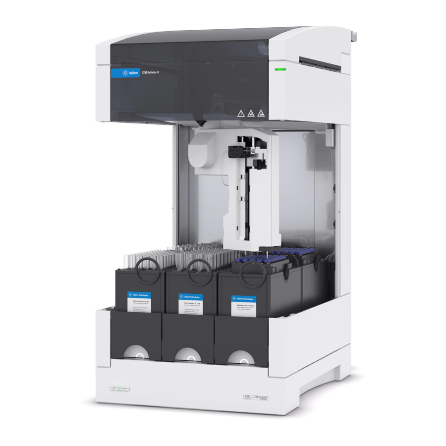
- Page 1 1290 Infinity II Preparative Open-Bed Sampler/Collector Agilent InfinityLab LC Series User Manual...
- Page 2 Agilent Technologies, Inc. as understood and met. furnishing, use, or performance of this governed by United States and interna- document or of any information con- tional copyright laws.
- Page 3 In This Guide This manual contains technical reference information about the Agilent 1290 Infinity II Preparative Open-Bed Sampler/Collector (G7158B). Introduction This chapter gives an introduction to the module and an instrument overview. Site Requirements and Specifications This chapter provides information on environmental requirements, physical and performance specifications.
- Page 4 Identifying Cables This chapter provides information on cables used with the module. Hardware Information This chapter describes the module in more detail on hardware and electronics. Appendix This chapter provides additional information on safety, legal, and web. 1290 Infinity II Preparative Open-Bed Sampler/Collector User Manual...
-
Page 5: Table Of Contents
Contents Introduction Intended Use Product Description Features Overview of the Module Leak and Waste Concept Site Requirements and Specifications Site Requirements Physical Specifications Performance Specifications Using the Sampler/Collector Warnings and Cautions Solvent Information Turn on/off Status Indicators Drawer Status Indicator Install the Preparative Loop Install or Replace the Analytical Loop Exchange Drawers... - Page 6 Preparing the Sampler/Collector Best Practices Capillary Color Coding Guide Swage Fittings Setting up the Sampler/Collector with the Instrument Control Interface Preparative Sampler Method Parameter Settings Fraction Collector Method Parameter Settings Pooling Challenging Samples Analytical to Preparative Switching Procedure Recommended Vials, Well Plates, and Containers Troubleshooting and Diagnostics User Interfaces Agilent Lab Advisor Software...
- Page 7 Electrical Connections Interfaces Setting the 6-bit Configuration Switch Early Maintenance Feedback Instrument Layout Appendix General Safety Information Waste Electrical and Electronic Equipment (WEEE) Directive Radio Interference Sound Emission Agilent Technologies on Internet 1290 Infinity II Preparative Open-Bed Sampler/Collector User Manual...
-
Page 8: Introduction
Introduction Intended Use Product Description Features Overview of the Module Leak and Waste Concept Leak Sensor This chapter gives an introduction to the module and an instrument overview. 1290 Infinity II Preparative Open-Bed Sampler/Collector User Manual... -
Page 9: Intended Use
Introduction Intended Use Intended Use The 1290 Infinity II Preparative Open-Bed Sampler/Collector is designed to be used in combination with other InfinityLab LC modules in a preparative-scale HPLC system to separate and purify inorganic or organic compounds via reversed-phase chromatography applications. The sampler can hold or store samples in containers such as vials, tubes, or well plates, draw a specified sample volume, and inject it into the reversed-phase HPLC system. -
Page 10: Product Description
Introduction Product Description Product Description The 1290 Infinity II Preparative Open-Bed Sampler/Collector is the solution for automated, high-capacity management of sample injection and fraction collection in semipreparative and preparative-scale LC purification workflows. The X-Z-theta axis probe uses novel robotic technology to minimize sample carryover during movements between fraction containers. -
Page 11: Features
Introduction Features Features • Fully automated and combined open-bed autosampler and fraction collector with capacity to inject up to 864 samples or collect up to 432 fractions, or combinations of both, in a single module to optimize bench space. • All sample and fraction vessels offer container recognition by identification tags and are easily accessible and can be exchanged during operation without stopping the instrument. -
Page 12: Overview Of The Module
Introduction Overview of the Module Overview of the Module The Preparative Open-Bed Sampler/Collector combines a preparative sampler with a preparative fraction collector in only one module. Figure 2 on page 12 gives an overview of the main module assemblies. Figure 3 on page 13 shows the sampling assembly and solvent distribution assembly in more detail. - Page 13 Introduction Overview of the Module Sampling assembly Solvent distribution assembly Solvent selection valves Solvent selection valves Metering pump Solvent divider Injection valve Peristaltic pumps Analytical loop Preparative loop Figure 3 Overview of the sampling assembly and solvent distribution assembly 1290 Infinity II Preparative Open-Bed Sampler/Collector User Manual...
-
Page 14: Leak And Waste Concept
Introduction Leak and Waste Concept Leak and Waste Concept Wash port assembly Sampler leak plane Leak plane holder Drain Outlet 1290 Infinity II Preparative Open-Bed Sampler/Collector User Manual... -
Page 15: Leak Sensor
Introduction Leak and Waste Concept Leak Sensor Figure 4 Sampler leak sensor Leak sensor Leak tray Figure 5 Position of leak tray and leak sensor 1290 Infinity II Preparative Open-Bed Sampler/Collector User Manual... - Page 16 Introduction Leak and Waste Concept Solvent incompatibility C AU T I O N The solvent DMF (dimethyl formamide) leads to corrosion of the leak sensor. The material of the leak sensor, PVDF (polyvinylidene fluoride), is incompatible with DMF. Do not use DMF as mobile phase. ...
-
Page 17: Site Requirements And Specifications
Site Requirements and Specifications Site Requirements Exhaust and Vapour Management Waste Management Physical Specifications Performance Specifications This chapter provides information on environmental requirements, physical and performance specifications. 1290 Infinity II Preparative Open-Bed Sampler/Collector User Manual... -
Page 18: Site Requirements
Site Requirements and Specifications Site Requirements Site Requirements A suitable environment is important to ensure optimal performance of the instrument. Power Considerations The module power supply has wide ranging capability. It accepts any line voltage in the range described in Table 1 on page 23. - Page 19 Never use a power cord other than the one that Agilent shipped with this instrument. Never use the power cords that Agilent Technologies supplies with this instrument for any other equipment. Never use cables other than the ones supplied by Agilent Technologies ...
- Page 20 Site Requirements and Specifications Site Requirements Bench Space The module dimensions and weight (see Table 1 on page 23) allow you to place the module on almost any desk or laboratory bench. It needs an additional 2.5 cm (1.0 inches) of space on either side and approximately 8 cm (3.1 inches) in the rear for air circulation and electric connections.
-
Page 21: Exhaust And Vapour Management
Site Requirements and Specifications Site Requirements Exhaust and Vapour Management You can operate the module in three different scenarios: 1 Under laboratory fume hood: • Ensure adequate fume hood ventilation: the recommended ventilation speed is 200 m /h with closed sash window and 490 m /h with open sash window. -
Page 22: Waste Management
Site Requirements and Specifications Site Requirements Waste Management Large amount of toxic, explosive, flammable, or corrosive solvents WAR N IN G Ensure that all waste is safely disposed according to your existing waste management solution. For details, refer to the Site Preparation Checklist. 1290 Infinity II Preparative Open-Bed Sampler/Collector User Manual... -
Page 23: Physical Specifications
Site Requirements and Specifications Physical Specifications Physical Specifications Table 1 Physical Specifications Type Specification Comments Weight 32 kg (70.5 lbs) Without any accessories and options Dimensions 781 x 393 x 622 mm (height × width × depth) (30.8 x 15.5 x 25.0 inches) Line voltage 100 –... -
Page 24: Performance Specifications
Site Requirements and Specifications Performance Specifications Performance Specifications Table 2 Performance Specifications Type Specification Comment Method/Conditions Delay volume Calculated using Lab Advisor. Dead volume in Valve tip appr. 30 µL Time to move from ves- 0.3 s Tested with OD 30 mm sel to vessel vessels. - Page 25 Site Requirements and Specifications Performance Specifications Table 2 Performance Specifications Type Specification Comment Method/Conditions Peak-based with time slice recov- The complete output of the fraction collector is recovered into separate slices of a specificed duration. When a peak is discovered by a peak trigger, fractions are collected in dedicated vessels.
- Page 26 Site Requirements and Specifications Performance Specifications Table 2 Performance Specifications Type Specification Comment Method/Conditions Trigger sources G7115A, 1260 Infinity II DAD G7165A, 1260 Infinity II MWD G7114A, 1260 Infinity II VWD G6120BA, LC/MS Single Quad VL G6130BA, LC/MS Single Quad SL G7121A, 1260 Infinity II FLD G4260B, 1260 Infinity II ELSD G7162A, 1260 Infinity II RID...
- Page 27 Site Requirements and Specifications Performance Specifications Table 2 Performance Specifications Type Specification Comment Method/Conditions Fraction/Sampler con- Tube Containers, ambient: compatible SBS containers for tainers Tube Container for 30 x 150 mm fractions and samples: tubes, ambient, 10 tubes • 2 mL vial holder (5023-2471) G9321-60015 •...
- Page 28 Site Requirements and Specifications Performance Specifications Table 2 Performance Specifications Type Specification Comment Method/Conditions Communication Controller Area Network (CAN), Local Area Network (LAN), ERI: ready, start, stop and shut-down signals Maintenance and Extensive diagnostics, error detec- safety-related features tion and display with Agilent Lab Advisor software.
- Page 29 Site Requirements and Specifications Performance Specifications Table 2 Performance Specifications Type Specification Comment Method/Conditions Cycle time < 28 s 100 µL injection volume, wash and plug setting inactive Injection precision - par- < 2 % Measured with Caffeine tial loop filling (prepara- in Water and Ethylpara- tive scale) ben in DMSO...
-
Page 30: Using The Sampler/Collector
Using the Sampler/Collector Warnings and Cautions Solvent Information Solvent Compatibility Wetted Materials General Information about Solvent/Material Compatibility Turn on/off Status Indicators Drawer Status Indicator Install the Preparative Loop Install a 1/16'' Preparative Loop Install a 1/8'' Preparative Loop Install or Replace the Analytical Loop Exchange Drawers Exchange Containers Replace the Fraction Collection Inlet/Outlet Tubings... -
Page 31: Warnings And Cautions
Using the Sampler/Collector Warnings and Cautions Warnings and Cautions Moving needle WAR N IN G Pinch hazard Do not grab into the robot area during operation. Be aware that the needle can move down even if the robot is on hold. ... -
Page 32: Solvent Information
Using the Sampler/Collector Solvent Information Solvent Information Toxic, flammable and hazardous solvents, samples and reagents WAR N IN G The handling of solvents, samples and reagents can hold health and safety risks. When working with these substances observe appropriate safety ... - Page 33 Using the Sampler/Collector Solvent Information Incompatible Solvents WAR N IN G Incompatible solvents can cause leaking. Leakage can result in fire hazard. Use only permitted solvents with this module. For details, see sections • Table 3 on page 34 , •...
- Page 34 Using the Sampler/Collector Solvent Information Permitted Solvents for Solvent Distribution Assembly Table 3 Permitted solvents for use in the low pressure area, connected to the Solvent Distribu- tion Assembly (S1, S2, and S3) Solvent Acetonitrile Ethanol Isopropanol Methanol Water Isopropanol easily dissolves the separating air plugs leading to mixing of the plugs and thus to lower re- covery.
- Page 35 Using the Sampler/Collector Solvent Information Priming Solvents Table 5 Choice of priming solvents Activity Solvent Comments After installation Methanol Best to flush air out of system Acetonitrile and metering pump Possible if no other solvent is Isopropanol available Cleaning the system Methanol Two-step wash (by default) with Acetonitrile...
-
Page 36: Solvent Compatibility
Using the Sampler/Collector Solvent Information Solvent Compatibility Solvent Compatibility for the 1290 Infinity II Preparative Open-Bed Sampler/Collector Solvents that get in contact with materials used in the 1290 Infinity II Preparative Open-Bed Sampler/Collector can cause corrosion in the module. For an overview of used materials, see “Wetted Materials”... - Page 37 Using the Sampler/Collector Solvent Information Table 8 Washport Component Material Connecting Tubing to Peristaltic Pump Silicone Connector Plug (for Connecting Tubing to Peri- Stainless Steel staltic Pump Wash-Port Base Polypropylene Waste Tube PTFE L and T Connectors PEEK Table 9 Outer needle wash Component Material...
-
Page 38: General Information About Solvent/Material Compatibility
Using the Sampler/Collector Solvent Information General Information about Solvent/Material Compatibility Materials in the flow path are carefully selected based on Agilent’s experiences in developing highest quality instruments for HPLC analysis over several decades. These materials exhibit excellent robustness under typical HPLC conditions. For any special condition, please consult the material information section or contact Agilent. - Page 39 Using the Sampler/Collector Solvent Information When used above room temperature, PEEK is sensitive to bases and various organic solvents, which can cause it to swell. Under such conditions, normal PEEK capillaries are very sensitive to high pressure. Therefore, Agilent uses stainless steel cladded PEEK capillaries in bio-inert systems.
- Page 40 Using the Sampler/Collector Solvent Information Stainless Steel (SST) Stainless steel is inert against many common solvents. It is stable in the presence of acids and bases in a pH range of 1 to 12.5. It can be corroded by acids below pH 2.3. It can also corrode in following solvents: •...
- Page 41 Using the Sampler/Collector Solvent Information Titanium (Ti) Titanium is highly resistant to oxidizing acids (for example, nitric, perchloric and hypochlorous acid) over a wide range of concentrations and temperatures. This is due to a thin oxide layer on the surface, which is stabilized by oxidizing compounds.
- Page 42 Using the Sampler/Collector Solvent Information Platinum/Iridium Platinum/Iridium is inert to almost all common acids, bases and solvents. There are no documented incompatibilities for HPLC applications. Fluorinated polymers (PTFE, PFA, FEP, FFKM, PVDF) Fluorinated polymers like PTFE (polytetrafluorethylene), PFA (perfluoroalkoxy), and FEP (fluorinated ethylene propylene) are inert to almost all common acids, bases, and solvents.
-
Page 43: Turn On/Off
Using the Sampler/Collector Turn on/off Turn on/off Plug in power cable. Power switch: On Power switch: Off Unplug the power cable. 1290 Infinity II Preparative Open-Bed Sampler/Collector User Manual... -
Page 44: Status Indicators
Using the Sampler/Collector Status Indicators Status Indicators The module status indicator indicates one of six possible module conditions: Status indicators 1: Idle 2: Run mode 3: Not-ready. Waiting for a specific pre-run condition to be reached or completed. 4: Error mode - interrupts the analysis and requires attention (for example a leak or defective internal components). 5: Resident mode (blinking) - for example during update of main firmware. -
Page 45: Drawer Status Indicator
Using the Sampler/Collector Drawer Status Indicator Drawer Status Indicator The drawer status indicator indicates one of three possible conditions: 1: off: drawer not detected 2: on: drawer detected and not in use = drawer can be pulled out 3: blinking: drawer detected and in use = drawer blocked NOTE Do not try to remove the drawer when the drawer status indicator is blinking. -
Page 46: Install The Preparative Loop
Using the Sampler/Collector Install the Preparative Loop Install the Preparative Loop Install a 1/16'' Preparative Loop Tools required Description 5810-0000 Hex driver SW-5 slitted 5023-2500 Spanner double open ended SW-5 Parts required Description 5068-0350 Preparative sample loop, stainless steel, 2 mL 5068-0351 Preparative sample loop, stainless steel, 5 mL, 1/16 inch Lift (1) and remove (2) the leak plane. -
Page 47: Install A 1/8'' Preparative Loop
Using the Sampler/Collector Install the Preparative Loop Install a 1/8'' Preparative Loop Tools required Description 8710-0510 Open-end wrench 1/4 — 5/16 inch 8710-0972 Open-end wrench 7/16 inch 5810-0000 Hex driver SW-5 slitted 5023-2500 Spanner double open ended SW-5 Parts required Description 5068-0334 Preparative sample loop, stainless steel, 5 mL... - Page 48 Using the Sampler/Collector Install the Preparative Loop Lift (1) and remove (2) the leak plane. Install the unions to the loop. NOTE To achieve maximale pressure tightness, always use Fer- rule 1/8-in-TBG-DIA SST (0100-1488). If another ferrule than Ferrule 1/8-in-TBG-DIA SST (0100-1488) is installed, remove this ferrule from the loop.
- Page 49 Using the Sampler/Collector Install the Preparative Loop Install the extension capillaries. Fix the union-loop assembly to the extension capil- lary-valve assembly. Swage the extension capillaries to the unions. • Use the 7/16'' wrench for the unions. • Use the 1/4'' wrench for the capillary. Remove the extension capillaries again from the union.
-
Page 50: Install Or Replace The Analytical Loop
Using the Sampler/Collector Install or Replace the Analytical Loop Install or Replace the Analytical Loop Tools required Description 5810-0000 Hex driver SW-5 slitted 5023-2500 Spanner double open ended SW-5 Parts required Description 5068-0348 Analytical sample loop Preparations Use LabAdvisor to move needle to waste position. Lift up (1) and remove (2) the leak plane. -
Page 51: Exchange Drawers
Using the Sampler/Collector Exchange Drawers Exchange Drawers Parts required Description G9321-60085 Drawer ambient G9321-60201 InfinityLab Drawer Gilson 207, ambient Toxic, flammable and hazardous solvents, samples and reagents WAR N IN G The handling of solvents, samples and reagents can hold health and safety risks. - Page 52 Using the Sampler/Collector Exchange Drawers Remove the drawer. Release the drawer by pushing the metal plate under- neath the drawer with the second hand. Exchange the drawer Install the drawer. 1290 Infinity II Preparative Open-Bed Sampler/Collector User Manual...
-
Page 53: Exchange Containers
Using the Sampler/Collector Exchange Containers Exchange Containers Parts required Description G9321-60015 Tube Container for 30 mm x 150 mm tubes, ambient, 10 tubes G9321-60058 Tube Container for 30 mm x 100 mm tubes, ambient, 10 tubes G9321-60025 Tube Container for 25 mm x 150 mm tubes, ambient, 18 tubes G9321-60035 Tube Container for 25 mm x 100 mm tubes, ambient, 18 tubes G9321-60129... - Page 54 Using the Sampler/Collector Exchange Containers Insert the new container. NOTE Mind the correct orientation of the container on the drawer. Check if the container is fixed properly ("Click"). 1290 Infinity II Preparative Open-Bed Sampler/Collector User Manual...
-
Page 55: Replace The Fraction Collection Inlet/Outlet Tubings
Using the Sampler/Collector Replace the Fraction Collection Inlet/Outlet Tubings Replace the Fraction Collection Inlet/Outlet Tubings Parts required Description G9321-60951 1290 Inf II PrepFC Tubing Kit 200 for flow rates up to 200 mL/min G9321-60952 1290 Inf II PrepFC Tubing Kit 50 for flow rates up to 50 mL/min G9321-60953 1290 Inf II PrepFC Tubing Kit 8 mL... - Page 56 Using the Sampler/Collector Replace the Fraction Collection Inlet/Outlet Tubings Open and remove the top fume hood. Open the tube holder. Swing up the fume hood against the mechanical stop. Remove the fume hood by pulling it toward you. Remove the tubings from the tube holder. Remove tubing clip and dongle from the fraction collec- tor.
- Page 57 Using the Sampler/Collector Replace the Fraction Collection Inlet/Outlet Tubings Remove the Inlet/Waste Tubings from the capillary Remove the tubings from under the clamp at the robot- holder. ics arm. Remove the delay sensor holder: Unlock the device with Unscrew the tubings from the valve assembly. the lever (1.), then pull out (2.).
- Page 58 Using the Sampler/Collector Replace the Fraction Collection Inlet/Outlet Tubings 11 Route the tubings under the clamp at the robotics arm. 12 Route the tubings clockwise (one turn) around the robotics arm. 13 Push the clip into the housing and connect the dongle. 14 Install the tubings to the tube holder.
- Page 59 Using the Sampler/Collector Replace the Fraction Collection Inlet/Outlet Tubings 17 Install the top fume hood and close it. Push the top fume hood into the recession. Close the top fume hood. 1290 Infinity II Preparative Open-Bed Sampler/Collector User Manual...
-
Page 60: Configuration And Operation Of The Open-Bed Sampler/Collector
Using the Sampler/Collector Configuration and Operation of the Open-Bed Sampler/Collector Configuration and Operation of the Open-Bed Sampler/Collector Delay Volumes and Delay Calibration Once software is installed and the fraction collector is ready to be operated, the fraction delay time needs to be determined. Figure 6 on page 60 shows a schematic drawing of the flow path between the detector and the fraction... - Page 61 Using the Sampler/Collector Configuration and Operation of the Open-Bed Sampler/Collector Figure 7 Chromatogram from a UV-detector with peak starting at t and ending at t Performing a Delay Calibration with an UV Detector 1 Place a vial containing the Delay Sensor Calibrant (5190-8223) in position 1 of the autosampler.
-
Page 62: Perfom A Delay Calibration Run In Openlab Cds Chemstation Edition
Using the Sampler/Collector Configuration and Operation of the Open-Bed Sampler/Collector Perfom a Delay Calibration Run in OpenLAB CDS Chemstation Edition The delay calibration procedure determines the delay time between detector(s) and the fraction collector in the system. The delay is used to compensate for the time a compound needs to travel between the point of detection in the detector and the point of collection in the fraction collector. -
Page 63: Help
Using the Sampler/Collector Configuration and Operation of the Open-Bed Sampler/Collector Help: Start The Start page of the Delay Calibration Wizard contains a description of the fraction collector delay calibration process, together with a schematic diagram of the connections for the detector and fraction collector. Cancel Closes the Delay Calibration Wizard without consequence. - Page 64 Using the Sampler/Collector Configuration and Operation of the Open-Bed Sampler/Collector Prepare Instrument for Calibration The Prepare Instrument page of the Delay Calibration Wizard leads you through the preparation of the instrument for the delay calibration run. The required preparation steps are listed in a three-column table: Activity A short description of the preparation activity.
- Page 65 Using the Sampler/Collector Configuration and Operation of the Open-Bed Sampler/Collector Perform Calibration Run Use the Perform Calibration page of the Delay Calibration Wizard to start the delay calibration run using the current method. The run parameters are listed; a warning is given if the method has been changed. You can switch to a different method or edit the sample information before starting the run.
-
Page 66: Delay Evaluation
Using the Sampler/Collector Configuration and Operation of the Open-Bed Sampler/Collector Delay Evaluation The Delay Evaluation window enables you to determine the delay times/volumes between the peak detector(s) and the fraction collector. The Delay Evaluation window is split into two sections: •... - Page 67 Using the Sampler/Collector Configuration and Operation of the Open-Bed Sampler/Collector Signals The Signals pane contains a signal plot for each peak detector, and one for the fraction collector delay sensor. By default, the largest peak in each signal plot is identified and highlighted as the target peak, but you can change the identification if there is more than one peak in the plot and the wrong peak has been identified.
-
Page 68: Setting Up A Fraction Collector Method
Using the Sampler/Collector Configuration and Operation of the Open-Bed Sampler/Collector Setting up a Fraction Collector Method Fraction Trigger Mode Use Timetable: Enables the Timetable, but requires a timetable event. Peak-based: If Peak-based is selected, the collection of a fraction is triggered by the signal of the detector. - Page 69 Peak Detectors In the Peak Detectors section a list of all peak detectors that are connected to the system is displayed. Agilent InfinityLab LC Series diode array detectors, multiwavelength detectors, variable wavelength detectors and fluorescence detectors are recognized automatically. Other detectors, e.g. Agilent 6000 mass-selective detectors or HP1050 detectors, are connected through the Universal Interface Box (UIB).
- Page 70 Using the Sampler/Collector Configuration and Operation of the Open-Bed Sampler/Collector Upper Threshold At high absorbance values the light intensity on the detector is extremely low and consequently detector noise will be superimposed on the detector signal. In this case the detector noise might trigger fraction collection. To avoid false fraction collection triggering, we recommend setting an Upper Threshold well below the limit where this false triggering effect might occur.
- Page 71 Using the Sampler/Collector Configuration and Operation of the Open-Bed Sampler/Collector Time In the time section of the dialog box the Stoptime and the Posttime for the fraction collector can be specified. By default the Stoptime is set to as pump and the posttime is switched OFF.
- Page 72 Using the Sampler/Collector Configuration and Operation of the Open-Bed Sampler/Collector Fraction Preview To determine the appropriate fraction collection parameters the Agilent ChemStation provides a valuable tool that becomes accessible by pushing the button labelled Fraction Preview Tool (see Figure 9 on page 72) in the Peak Detectors section.
-
Page 73: Prepare The Module For Transportation
Using the Sampler/Collector Prepare the Module for Transportation Prepare the Module for Transportation When • For transportation within the laboratory • For shipping the module Parts required Description G9321-40165 Protect-Foam Y-Axis G9321-40108 Protect Foam G9321-22233 Shipping Block Preparations • Remove all containers and drawers. •... - Page 74 Using the Sampler/Collector Prepare the Module for Transportation Using "Single Steps" from the Service and Diagnostics Power down the module. section in Lab Advisor, move the robotics to the park Place the Protect-Foam Y-Axis (G9321-40165) in the position. back of the Y-axis arm. 120°...
- Page 75 Using the Sampler/Collector Prepare the Module for Transportation Move the shipping block backward on the rail until the Fix the shipping bolt with the M3 screw. two screwholes of the shipping block and the rail lie on top of each other. 10 For shipping the module to another location, position the module in the transportation box and fix it correctly.
-
Page 76: Preparing The Sampler/Collector
Preparing the Sampler/Collector Best Practices Daily Startup Routine Prepare the Sampler/Collector Using the Fraction Collector Regular Inspections Capillary Color Coding Guide Swage Fittings Setting up the Sampler/Collector with the Instrument Control Interface Overview Instrument Configuration Preparative Sampler User Interface (Dashboard Panel) Preparative Sampler Control Parameters Fraction Collector User Interface (Dashboard Panel) Preparative Sampler Method Parameter Settings... -
Page 77: Best Practices
Preparing the Sampler/Collector Best Practices Best Practices Daily Startup Routine • Check that the robotics are not obstructed. • Use the default wash that comprises aqueous and organic wash for ideal performance of sample transport and sample positioning. It allows for: •... -
Page 78: Prepare The Sampler/Collector
Preparing the Sampler/Collector Best Practices Prepare the Sampler/Collector • Fill the solvent bottles with the following solvents: • S1 = draw solvent: water • S2: organic wash solvent, use methanol or acetonitrile (see Table 5 page 35) • S3: to be selected by the user •... -
Page 79: Capillary Color Coding Guide
Preparing the Sampler/Collector Capillary Color Coding Guide Capillary Color Coding Guide Figure 11 Syntax for capillary description 1290 Infinity II Preparative Open-Bed Sampler/Collector User Manual... -
Page 80: Swage Fittings
Preparing the Sampler/Collector Swage Fittings Swage Fittings Select a nut that is long enough for the fitting you'll be Slide the nut over the end of the tubing or capillary. using. Carefully slide the ferrule components on after the nut Use a column or injection valve to gently tighten the fit- and then finger-tighten the assembly while ensuring ting which forces the ferrule to seat onto the tubing or... - Page 81 Preparing the Sampler/Collector Swage Fittings Loosen the nut and verify that the ferrule is correctly positioned on the tubing or capillary. The first time that the swagelock fitting is used on a column or an injection valve, NOTE the position of the ferrule is permanently set. If changing from a column or an injection valve to another, the fitting may leak or decrease the quality of the separation by contributing to band broadening.
-
Page 82: Setting Up The Sampler/Collector With The Instrument Control Interface
Preparing the Sampler/Collector Setting up the Sampler/Collector with the Instrument Control Interface Setting up the Sampler/Collector with the Instrument Control Interface Overview Parameters described in following sections are offered by the instrument control interface and can usually be accessed through Agilent instrument control software. - Page 83 Preparing the Sampler/Collector Setting up the Sampler/Collector with the Instrument Control Interface Instrument Configuration Prep Sampler (G7169B) Figure 12 Instrument configuration (G7169B) 1290 Infinity II Preparative Open-Bed Sampler/Collector User Manual...
- Page 84 Preparing the Sampler/Collector Setting up the Sampler/Collector with the Instrument Control Interface The Preparative Sampler configuration parameters are in three sections: • Communication • Options • Connected Fraction and Recovery Collectors Table 11 Instrument configuration parameters (G7169B) Parameter Description Communication: The parameters in this dialog box are detected automatically during autoconfiguration.
- Page 85 Preparing the Sampler/Collector Setting up the Sampler/Collector with the Instrument Control Interface Instrument Configuration Fraction Collector (G7159B) Figure 13 Instrument Configuration 1290 Infinity II Preparative Open-Bed Sampler/Collector User Manual...
- Page 86 Preparing the Sampler/Collector Setting up the Sampler/Collector with the Instrument Control Interface The Fraction Collector configuration parameters are in four sections: • Communication • Module List • Peak Detectors • Linked Pump Table 12 Instrument configuration parameters Parameter Description Communication: The parameters in this dialog box are detected automatically during autoconfigura- tion.
- Page 87 Preparing the Sampler/Collector Setting up the Sampler/Collector with the Instrument Control Interface Table 12 Instrument configuration parameters Parameter Description Peak Detectors: • Module type: product number of the peak detector detected during autoconfiguration • Serial number: serial number of the peak detector detected during autoconfiguration •...
-
Page 88: Preparative Sampler User Interface (Dashboard Panel)
Preparing the Sampler/Collector Setting up the Sampler/Collector with the Instrument Control Interface Preparative Sampler User Interface (Dashboard Panel) Table 13 Preparative Sampler user interface Parameter Description Module graphic The items in the Preparative Sampler graphic have the follow- ing meaning and function: •... - Page 89 Preparing the Sampler/Collector Setting up the Sampler/Collector with the Instrument Control Interface Table 13 Preparative Sampler user interface Parameter Description Context Menu The context menu of the dashboard panel contains the fol- lowing commands: • Control: Displays the sampler's Control dialog box. “Preparative Sampler Control Parameters”...
-
Page 90: Preparative Sampler Control Parameters
Preparing the Sampler/Collector Setting up the Sampler/Collector with the Instrument Control Interface Preparative Sampler Control Parameters Figure 14 Preparative Sampler Control parameters The Preparative Sampler Control parameters are in two sections: • Pump providing preparative flow: Use this section to specify the pump that is used to deliver the flow in Preparative operation mode. -
Page 91: Fraction Collector User Interface (Dashboard Panel)
Preparing the Sampler/Collector Setting up the Sampler/Collector with the Instrument Control Interface Fraction Collector User Interface (Dashboard Panel) Table 14 Fraction Valve User Interface Parameter Description Module graphic The items in the Fraction Collector graphic have the following meaning and function: •... - Page 92 Preparing the Sampler/Collector Setting up the Sampler/Collector with the Instrument Control Interface Table 14 Fraction Valve User Interface Parameter Description Context Menu The context menu of the dashboard panel contains the following commands: • Method: Displays the Fraction Collector's Method Setup dialog box.
-
Page 93: Preparative Sampler Method Parameter Settings
Preparing the Sampler/Collector Preparative Sampler Method Parameter Settings Preparative Sampler Method Parameter Settings Figure 15 Preparative Sampler method settings 1290 Infinity II Preparative Open-Bed Sampler/Collector User Manual... - Page 94 Preparing the Sampler/Collector Preparative Sampler Method Parameter Settings The Preparative Sampler method parameters are in up to twelve sections: • Operation Mode • Method Preset • Injection • Wash Settings • Sample Dilution • Sample Homogenization • Stoptime • Posttime •...
- Page 95 Preparing the Sampler/Collector Preparative Sampler Method Parameter Settings Table 15 Method parameter settings Parameter Description Operation Mode The selected operation mode determines the maximum injec- tion volume, based on the configured loop. Select Preparative mode to use the currently configured Pre- parative Loop, or Analytical mode to use the currently config- ured Analytical Loop.
- Page 96 Preparing the Sampler/Collector Preparative Sampler Method Parameter Settings Table 15 Method parameter settings Parameter Description Wash Settings • During Run: Off - no Multi-wash is performed. Multi-wash at Start of Post Run - the Multi-wash is exe- cuted at the start of the post-run period in accordance with the parameters set up under Injection Path Cleaning (see “Injection Path Cleaning”...
- Page 97 Preparing the Sampler/Collector Preparative Sampler Method Parameter Settings Table 15 Method parameter settings Parameter Description Stoptime The Stoptime sets a time limit for your analysis. Limits: 0.01 – 99999 min or As Pump/No Limit. Posttime You can set the Posttime so that your remains in a post-run state during the Posttime to delay the start of the next analy- sis.
-
Page 98: Plug Settings
Preparing the Sampler/Collector Preparative Sampler Method Parameter Settings Plug Settings Plug settings are automatically set depending on your sample matrix when using the Method Presets. It is recommended to use the plug settings as mentioned in Select Method Preset: • Plug setting 1 for polar sample matrix •... - Page 99 Preparing the Sampler/Collector Preparative Sampler Method Parameter Settings Plug Setting 1 Figure 16 Plug Setting 1 The Sample plug is followed by an optional three-part Loop Solvent plug and Positioning Plug. The Loop Solvent plugs and Positioning Plug use the current solvent composition from the method.
- Page 100 Preparing the Sampler/Collector Preparative Sampler Method Parameter Settings Plug Setting 2 Figure 17 Plug Setting 2 The Post-sample Plug can either be a pure organic solvent or a mixture of organic solvent and water. It provides a higher transport capacity of sample through the tubing to the injector valve for cases where the polarity of the analytes and of the loop content, which is based on the start gradient, do not match.
- Page 101 Preparing the Sampler/Collector Preparative Sampler Method Parameter Settings Default settings (preparative and analytical operation mode): 180 µL with 25 % methanol. If precipitation occurs in the sampling flow path, increase the organic composition of the post-sample plug for preparative applications or switch to plug setting 3.
- Page 102 Preparing the Sampler/Collector Preparative Sampler Method Parameter Settings Plug Setting 3 Figure 18 Plug Setting 3 The Sample plug is preceded by an optional Pre-sample Sandwich Plug, and followed by an optional Post-sample Sandwich Plug. These are followed by an optional three-part Post-sample Plug and Positioning Plug.
- Page 103 Preparing the Sampler/Collector Preparative Sampler Method Parameter Settings however, the use of some special characters may reduce this limit. Specify the total volume of the Post-sample Plug in the adjacent field; the volume you specify is divided equally between the parts. Click the down-arrow and specify the location of the solvent for the Post-sample Plug from the drop-down list;...
- Page 104 Preparing the Sampler/Collector Preparative Sampler Method Parameter Settings Some organic solvents are not recommended to be used as sandwich and post-sample plug solvents, mainly due to their physicochemical properties: • Isopropanol easily dissolves the separating air plugs leading to mixing of the plugs and thus to lower recovery.
-
Page 105: Advanced Settings
Preparing the Sampler/Collector Preparative Sampler Method Parameter Settings Advanced Settings Figure 19 Advanced settings The Preparative Sampler advanced method parameters are in two sections: • Sampling Speed • Needle Height Position Table 16 Advanced parameters description Parameter Description Sampling Speed •... - Page 106 Preparing the Sampler/Collector Preparative Sampler Method Parameter Settings Table 16 Advanced parameters description Parameter Description Needle Height Position • Offset: This is a vertical offset that enables you to position the needle a specific distance (in mm) away from its stan- dard position.
-
Page 107: Injection Path Cleaning
Preparing the Sampler/Collector Preparative Sampler Method Parameter Settings Injection Path Cleaning Figure 20 Injection path cleaning The Multi-wash table allows you to specify up to four steps that will be used to clean the system. The Start Cond. step is obligatory; you cannot switch it off. However, you can switch off the Needle Outer wash if it is not required to avoid precipitation of high concentrated sample at the needle tip. -
Page 108: Dilution
Preparing the Sampler/Collector Preparative Sampler Method Parameter Settings Dilution Figure 21 Dilution settings The Dilution section is available only for the Analytical operation mode, and only when enabled in the Sample Dilution section. It allows you to dilute concentrated samples before injection. Ensure using a vessel with sufficient volume to hold the diluted sample. - Page 109 Preparing the Sampler/Collector Preparative Sampler Method Parameter Settings The following parameters must be specified: • Draw Dilution Solvent • Dilution Factor: Choose this option to specify a dilution factor in the adjacent field. Valid range: 2 – 200 • Dilution Volume: Choose this option to specify a volume of solvent with which to dilute the sample.
-
Page 110: Fraction Collector Method Parameter Settings
Preparing the Sampler/Collector Fraction Collector Method Parameter Settings Fraction Collector Method Parameter Settings Figure 22 Method settings 1290 Infinity II Preparative Open-Bed Sampler/Collector User Manual... - Page 111 Preparing the Sampler/Collector Fraction Collector Method Parameter Settings The Fraction Collector method setup parameters are in eight sections: • Collection Behavior • Peak Triggers • Trigger Combinations • Stoptime • Posttime • Advanced • Timetable • Fraction Preview Table 17 Method Parameter Settings Parameter Description...
- Page 112 Preparing the Sampler/Collector Fraction Collector Method Parameter Settings Table 17 Method Parameter Settings Parameter Description Trigger Combinations Use the Trigger Combinations to specify how multi- ple peak triggers are combined to start or stop Fraction Collection. You can choose that: •...
-
Page 113: Advanced Settings
Preparing the Sampler/Collector Fraction Collector Method Parameter Settings Advanced Settings Figure 23 Advanced settings The Fraction Collector method setup advanced parameters are in three sections, depending on the configuration: • Delay Settings • Fill Volume Settings • 3rd Party Pump Flow (only visible if there is no Agilent pump recognized.) 1290 Infinity II Preparative Open-Bed Sampler/Collector User Manual... - Page 114 Preparing the Sampler/Collector Fraction Collector Method Parameter Settings Table 18 Advanced Parameters Description Parameter Description Delay Settings Use the Delay Settings table to specify the delay that is applied to a peak trigger signal. You can specify this setting for each peak detector sepa- rately.
-
Page 115: Timetable Settings
Preparing the Sampler/Collector Fraction Collector Method Parameter Settings Timetable Settings A timetable entry is crucial to enable any fraction collection. NOTE Figure 24 Timetable settings Use the Timetable to program changes in the fraction collector parameters during the analysis by entering a time in the Time field and appropriate values in the following fields of the timetable. - Page 116 Preparing the Sampler/Collector Fraction Collector Method Parameter Settings Table 19 Timetable Functions Function Parameters Fraction Mode • Off (Turns off the current fraction collection, where you use Off to turn off fraction collection at the end of the run if you have not specified a Stoptime) •...
- Page 117 Preparing the Sampler/Collector Fraction Collector Method Parameter Settings Table 19 Timetable Functions Function Parameters Trigger Settings • Trigger Source (Click the down-arrow and select the trigger source from the drop-down list) • Peak Detection Mode (Click the down-arrow and select the peak detection mode from the drop-down list).
-
Page 118: Pooling
Preparing the Sampler/Collector Pooling Pooling Pooling is the collection of multiple fractions into the same collection vessel. You can pool fractions from either multiple injections of the same sample or single injections of different samples. Fractions are pooled automatically when you specify multiple injections from the same location in one line of the sequence table, or if the same fraction start location is specified for sequential locations in the sequence table. -
Page 119: Challenging Samples
Preparing the Sampler/Collector Challenging Samples Challenging Samples If the transfer of sample/solvent from the needle to the injection valve shows disintegrating air plugs and/or mixing of sample, post-sample plugs and/or start gradient, reducing the positioning speed is the most effective parameter to reduce these effects. -
Page 120: Analytical To Preparative Switching Procedure
Preparing the Sampler/Collector Analytical to Preparative Switching Procedure Analytical to Preparative Switching Procedure Switch from Analytical to Preparative Flow Path When switching from analytical to preparative flow path of the system, no specific wash or conditioning procedure takes place. The preparative part of the system remains flushed in the final solvent composition of the last preparative run. -
Page 121: Recommended Vials, Well Plates, And Containers
Preparing the Sampler/Collector Recommended Vials, Well Plates, and Containers Recommended Vials, Well Plates, and Containers Vials • Always use the Vial bracket (G9321-40160) for vials that are covered by a septum. As the robot has no pusher, the vials are lifted in every exit needle operation. - Page 122 Preparing the Sampler/Collector Recommended Vials, Well Plates, and Containers Overview on SBS Container Plates Table 20 Overview of SBS container plates Agilent part ChemStation name Name Compatible Max. allowed fill SBS level number sealing volume [mL] 5043-9300 A_5043-9360_96_2.2mL 96 wellplate 2.2 mL 1.98 2nd highest 5043-9302...
-
Page 123: Troubleshooting And Diagnostics
Troubleshooting and Diagnostics User Interfaces Agilent Lab Advisor Software This chapter gives an overview about the troubleshooting and diagnostic features and the different user interfaces. 1290 Infinity II Preparative Open-Bed Sampler/Collector User Manual... -
Page 124: User Interfaces
Troubleshooting and Diagnostics User Interfaces User Interfaces • Depending on the user interface, the available tests and the screens/reports may vary. • Preferred tool should be Agilent Lab Advisor Software, see “Agilent Lab Advisor Software” on page 125. • The Agilent OpenLAB ChemStation C.01.03 and above do not include any maintenance/test functions. -
Page 125: Agilent Lab Advisor Software
Lab Advisor Advanced Lab Advisor Basic is included with every Agilent 1200 Infinity Series and Agilent InfinityLab LC Series instrument. The Lab Advisor Advanced features can be unlocked by purchasing a license key, and include real-time monitoring of instrument actuals, all various instrument signals, and state machines. -
Page 126: Error Information
Error Information What Are Error Messages General Error Messages Timeout Shutdown Remote Timeout Lost CAN Partner Leak Sensor Short Leak Sensor Open Compensation Sensor Open Compensation Sensor Short Fan Failed Leak This chapter describes the meaning of error messages, and provides information on probable causes and suggested actions how to recover from error conditions. - Page 127 Error Information What Are Error Messages What Are Error Messages Error messages are displayed in the user interface when an electronic, mechanical, or hydraulic (flow path) failure occurs which requires attention before the analysis can be continued (for example, repair, or exchange of consumables is necessary).
-
Page 128: Timeout
Error Information General Error Messages General Error Messages General error messages are generic to all Agilent series HPLC modules and may show up on other modules as well. Timeout Error ID: 0062 The timeout threshold was exceeded. Probable cause Suggested actions Check the logbook for the occurrence and source The analysis was completed successfully, of a not-ready condition. -
Page 129: Shutdown
Error Information General Error Messages Shutdown Error ID: 0063 An external instrument has generated a shutdown signal on the remote line. The module continually monitors the remote input connectors for status signals. A LOW signal input on pin 4 of the remote connector generates the error message. -
Page 130: Remote Timeout
Error Information General Error Messages Remote Timeout Error ID: 0070 A not-ready condition is still present on the remote input. When an analysis is started, the system expects all not-ready conditions (for example, a not-ready condition during detector balance) to switch to run conditions within one minute of starting the analysis. -
Page 131: Leak Sensor Short
Error Information General Error Messages Leak Sensor Short Error ID: 0082 The leak sensor in the module has failed (short circuit). The current through the leak sensor is dependent on temperature. A leak is detected when solvent cools the leak sensor, causing the leak sensor current to change within defined limits. -
Page 132: Compensation Sensor Open
Error Information General Error Messages Compensation Sensor Open Error ID: 0081 The ambient-compensation sensor (NTC) on the main board in the module has failed (open circuit). The resistance across the temperature compensation sensor (NTC) on the main board is dependent on ambient temperature. The change in resistance is used by the leak circuit to compensate for ambient temperature changes. -
Page 133: Fan Failed
Error Information General Error Messages Fan Failed Error ID: 0068 The cooling fan in the module has failed. The hall sensor on the fan shaft is used by the main board to monitor the fan speed. If the fan speed falls below a certain limit for a certain length of time, the error message is generated. -
Page 134: Maintenance
Maintenance Introduction to Maintenance Warnings and Cautions Cleaning the Module Overview of Maintenance Install and Remove the Top Fume Hood Clean the Leak Pan Replace the Dripping Adapter for the Fraction Valve Replace the Rotor Seal Replace the Stator Replace the two Peristaltic Pump Cartridges Replace the Needle Wash Plug Assembly Install or Replace the Sampling Unit Tubing Kit Install or Replace the Solvent Distribution Tubing... -
Page 135: Introduction To Maintenance
Maintenance Introduction to Maintenance Introduction to Maintenance The module is designed for easy maintenance. Maintenance can be done from the front with module in place in the system. There are no serviceable parts inside. NOTE Do not open the module. 1290 Infinity II Preparative Open-Bed Sampler/Collector User Manual... -
Page 136: Warnings And Cautions
Maintenance Warnings and Cautions Warnings and Cautions Moving needle WAR N IN G Pinch hazard Do not grab into the robot area during operation. Be aware that the needle can move down even if the robot is on hold. ... - Page 137 Maintenance Warnings and Cautions Sharp metal edges WAR N IN G Sharp-edged parts of the equipment may cause injuries. To prevent personal injury, be careful when getting in contact with sharp metal areas. Toxic, flammable and hazardous solvents, samples and reagents WAR N IN G The handling of solvents, samples and reagents can hold health and safety risks.
-
Page 138: Cleaning The Module
Maintenance Cleaning the Module Cleaning the Module To keep the module case clean, use a soft cloth slightly dampened with water, or a solution of water and mild detergent. Liquid dripping into the electronic compartment of your module can cause WAR N IN G shock hazard and damage the module Do not use an excessively damp cloth during cleaning. -
Page 139: Overview Of Maintenance
Maintenance Overview of Maintenance Overview of Maintenance The procedures described in this section can be done with the Sampler/Collector in place in the stack. These procedures can be done on a more frequent basis. Table 21 Overview of maintenance procedures. Procedure Typical Frequency Notes... -
Page 140: Install And Remove The Top Fume Hood
Maintenance Install and Remove the Top Fume Hood Install and Remove the Top Fume Hood Parts required Description G9321-68200 Top Fume Hood Kit See chapter Parts for details. Install the exhaust sheet by fixing the four screws to the Install the top fume hood and close it. fraction collector. - Page 141 Maintenance Install and Remove the Top Fume Hood Open and remove the top fume hood. Remove the screws fixing the exhaust sheet to the frac- tion collector, then remove the exhaust sheet. Swing up the fume hood against the mechanical stop.
-
Page 142: Clean The Leak Pan
Maintenance Clean the Leak Pan Clean the Leak Pan Preparations • Turn off the flow and the instrument. • Remove all drawers from the module. • Move the robotics to the home position. Pull the release knobs on both sides at the front of the Open the guide support assembly (1.) and fix it at the guide support assembly. -
Page 143: Replace The Dripping Adapter For The Fraction Valve
Maintenance Replace the Dripping Adapter for the Fraction Valve Replace the Dripping Adapter for the Fraction Valve Tools required Description 5067-7028 Z-Axe Maintenance Tool This tool has a bifunctional shank. One side serves as a tool for exchanging the needle tubing. The other side is designed for removing and installing of the dripping adapter. - Page 144 Maintenance Replace the Dripping Adapter for the Fraction Valve Use Z-Axe Maintenance Tool (5067-7028) to clip the Remove Z-Axe Maintenance Tool (5067-7028). new dripping adapter on to the end of the fraction valve. Clip and lock the Needle Wash Plug Assembly Holder back in place at the bottom of the Z-Arm Assembly.
-
Page 145: Replace The Rotor Seal
Maintenance Replace the Rotor Seal Replace the Rotor Seal When • Poor injection volume reproducibility • Leaking injection valve Parts required Description 5068-0323 Rotor seal Preparations Finish any pending acquisition job and in order to avoid leaks, stop the pump running. Reduced life time of the injection valve C AU T I O N Component cleanliness is crucial for the life time of the injection valve. - Page 146 Maintenance Replace the Rotor Seal Remove the rotor seal. C AU T I O N Damage to the stator head The polished sealing surface of the stator head contains thirteen ports that excessive handling can easily damage. Avoid touching the polished surface of the stator head. ...
- Page 147 Maintenance Replace the Rotor Seal Reinstall the stator head. The index pins on the drive C AU T I O N and the stator head must engage in the corresponding holes. Insert the socket head screws. Damage to the rotor seal and cross-port leaks ...
- Page 148 Maintenance Replace the Rotor Seal Using a torx screwdriver, tighten each screw gently until Reconnect the loops, capillaries, and tubings to the you feel resistance (approximately fingertight). Tighten injection valve with a 1/4 inch wrench. each screw by 1/8 turn, and then tighten each screw again, until the stator is secured to the driver.
-
Page 149: Replace The Stator
Maintenance Replace the Stator Replace the Stator When After three rotor seal replacements Parts required Description 5068-0322 Stator Preparations Finish any pending acquisition job and in order to avoid leaks, stop the pump running. Reduced life time of the injection valve C AU T I O N Component cleanliness is crucial for the life time of the injection valve. - Page 150 Maintenance Replace the Stator Reinstall the stator head. The index pins on the drive C AU T I O N and the stator head must engage in the corresponding holes. Insert the socket head screws. Damage to the stator head The polished sealing surface of the stator head contains thirteen ports that excessive handling can easily damage.
-
Page 151: Replace The Two Peristaltic Pump Cartridges
Maintenance Replace the two Peristaltic Pump Cartridges Replace the two Peristaltic Pump Cartridges When • Every 3 months of operation • Tubing blocked or broken Parts required Description 5067-6668 Peristaltic pump head Preparations To avoid spilling of solvents, remove the solvent lines from the bottles. When opening capillary or tube fittings solvents may leak out. - Page 152 Maintenance Replace the two Peristaltic Pump Cartridges Disconnect the tubing couplers. Twist and then pull the cartridge forward off the motor shaft. Push and then twist the new cartridge onto the motor Reconnect the tubing couplers and the tubings. shaft until the clips click into place. 1290 Infinity II Preparative Open-Bed Sampler/Collector User Manual...
-
Page 153: Replace The Needle Wash Plug Assembly
Maintenance Replace the Needle Wash Plug Assembly Replace the Needle Wash Plug Assembly Parts required Description G9321-60036 Needle Wash Plug Assembly Remove the needle wash plug assembly Unclip the Needle Wash Plug Assembly to completely C AU T I O N remove it, while feeding the needle wash tubing. - Page 154 Maintenance Replace the Needle Wash Plug Assembly Disconnect the 1/8 tubing from the Solvent Divider assembly. Install the needle wash plug assembly Clip and lock the Needle Wash Plug Assembly Holder Reroute the tubing around the Z-Arm. back in place at the bottom of the Z-Arm Assembly. Route the tubing to the left of the Theta Interface and Slide the new Tube Holder in place on the Theta Assem- around the back towards the front of Theta to mount...
- Page 155 Maintenance Replace the Needle Wash Plug Assembly Guide the tubing through the tubing holder next to the Plumb the 1/8 fitting into the Solvent Divider Assembly. metering pump and then in the direction of the solvent divider assembly. 1290 Infinity II Preparative Open-Bed Sampler/Collector User Manual...
-
Page 156: Install Or Replace The Sampling Unit Tubing Kit
Maintenance Install or Replace the Sampling Unit Tubing Kit Install or Replace the Sampling Unit Tubing Kit Tools required Description 5043-1471 Fitting Handle Parts required Description G9321-68006 Sampling Unit Tubing Kit Contains Sample Tubing Short (5500-1417), and Sample Tubing Long (5500-1418) Preparations Use Lab Advisor to move the needle to the waste position. -
Page 157: Install Or Replace The Solvent Distribution Tubing
Maintenance Install or Replace the Solvent Distribution Tubing Install or Replace the Solvent Distribution Tubing Tools required Description 5043-1471 Fitting Handle Parts required Description G7120-60007 Bottle Head Assembly 5500-1429 Solvent Distribution Tubing Kit Install Bottle Head Assemblies (G7120-60007). Install the short silicon tubing to the rear exit port of the solvent divider block (1). - Page 158 Maintenance Install or Replace the Solvent Distribution Tubing Install the long tubing between the left rear connector of Install the 2 tubing between lower outlet of the Sol- the Solvent Divider Block (1) to the inlet of the Metering vent Selection Valve (1) to front of the Solvent Divider Pump (2).
-
Page 159: Install Or Replace The Needle Tubing
Maintenance Install or Replace the Needle Tubing Install or Replace the Needle Tubing Tools required Description 5043-1471 Fitting Handle 5067-7028 Z-Axe Maintenance Tool Parts required Description G9321-60737 Needle Tubing Kit Preparations Use Lab Advisor procedure "Change needle or needle tubing" and follow the on-screen instructions. The illustrations only show the installation. - Page 160 Maintenance Install or Replace the Needle Tubing Connect the fitting on the solvent selection valve left Mount the black clip in the middle position (second slot outlet position with Fitting Handle (5043-1471). on the left side) on the Theta housing and insert the dongle.
-
Page 161: Replace The Module Firmware
Maintenance Replace the Module Firmware Replace the Module Firmware When The installation of newer firmware might be necessary • if a newer version solves problems of older versions or • to keep all systems on the same (validated) revision. The installation of older firmware might be necessary •... -
Page 162: Parts For Maintenance And Repair
Parts for Maintenance and Repair Supported Containers List of Recommended Fraction Tubes Sampler/Collector Accessory Kit Tubing Kits Top Fume Hood Kit This chapter provides information on parts for maintenance and repair. 1290 Infinity II Preparative Open-Bed Sampler/Collector User Manual... -
Page 163: Supported Containers
Parts for Maintenance and Repair Supported Containers Supported Containers Description G9321-60015 Tube Container for 30 mm x 150 mm tubes, ambient, 10 tubes G9321-60058 Tube Container for 30 mm x 100 mm tubes, ambient, 10 tubes G9321-60025 Tube Container for 25 mm x 150 mm tubes, ambient, 18 tubes G9321-60035 Tube Container for 25 mm x 100 mm tubes, ambient, 18 tubes G9321-60129... -
Page 164: List Of Recommended Fraction Tubes
Parts for Maintenance and Repair List of Recommended Fraction Tubes List of Recommended Fraction Tubes Description 5190-9090 Fraction Tubes 150 mm x 30 mm, 78 mL (pack of 100) fits with p/n G9321-60015 5042-6458 Fraction Tubes 100 mm x 30 mm, 50 mL (pack of 100) fits with p/n G9321-60058 5190-9091 Fraction Tubes 150 mm x 25 mm, 55 mL (pack of 100) -
Page 165: Sampler/Collector Accessory Kit
Parts for Maintenance and Repair Sampler/Collector Accessory Kit Sampler/Collector Accessory Kit Fraction Collector Accessory Kit The Fraction Collector Accessory Kit (G9321-68002) contains the following items: Description 5065-9971 Barbed Y-Connector, PP for 3/16 in ID Tube 5181-1519 CAN cable, Agilent module to module, 1 m 5500-1155 Tube Connector, 90 degree, ID 6.4 5063-6527... -
Page 166: Tubing Kits
Parts for Maintenance and Repair Tubing Kits Tubing Kits Tubing Kit G9321-60951 1290 Inf II PrepFC Tubing Kit 200 (G9321-60951) contains the following parts: Description G9321-40081 Delay Sensor Clip G9321-40128 Tube holder 5023-2878 2.4 m Tubing ESD PTFE (OD2/ID1.2) 5023-2636 2.4 m Tubing ESD PTFE (OD2.5/OD1.6) 5023-2871 Fitting 1/4-28 for Tube-OD 2.5 mm ESD-PEEK... - Page 167 Parts for Maintenance and Repair Tubing Kits Tubing Kit G9321-60952 1290 Inf II PrepFC Tubing Kit 50 (G9321-60952) contains the following parts: Description G9321-40081 Delay Sensor Clip G9321-40128 Tube holder 5067-6785 EEPROM tag assembly 5023-2637 2.4 m Tubing ESD PTFE (OD1.6/ID0.8) 5023-2636 2.4 m Tubing ESD PTFE (OD2.5/OD1.6) 5023-2871...
- Page 168 Parts for Maintenance and Repair Tubing Kits Tubing Kit G9321-60953 1290 Inf II PrepFC Tubing Kit 8 mL (G9321-60953) contains the following parts: Description G9321-40081 Delay Sensor Clip G9321-40128 Tube holder 5067-6785 EEPROM tag assembly 5023-3072 2.4 m Tubing ESD PTFE (OD1.6/ID0.5) 5023-2636 2.4 m Tubing ESD PTFE (OD2.5/OD1.6) 5023-2874...
- Page 169 Parts for Maintenance and Repair Tubing Kits Tubing Kit G9321-60954 1290 Inf II PrepFC Tubing Kit 150 mL (G9321-60954) contains the following parts: Description G9321-40081 Delay Sensor Clip G9321-40128 Tube holder 5067-6785 EEPROM tag assembly 5023-2878 2.4 m Tubing ESD PTFE (OD2/ID1.2) 5023-2636 2.4 m Tubing ESD PTFE (OD2.5/OD1.6) G9321-87713...
-
Page 170: Top Fume Hood Kit
Parts for Maintenance and Repair Top Fume Hood Kit Top Fume Hood Kit Item Description G9321-68200 Top Fume Hood Kit contains the following items: G9321-60830 Top Fume Hood 0515-1753 SCREW-MACH-M3X0.5-8MM-LG-PAN-HD G9321-00100 Exhaust Sheet G1364-03201 Exhaust Tube Adapter 5067-5406 Screw Tx20, M4 x 8 mm Figure 25 Top Fume Hood Kit 1290 Infinity II Preparative Open-Bed Sampler/Collector User Manual... -
Page 171: Identifying Cables
Identifying Cables Cable Overview Analog Cables Remote Cables CAN/LAN Cables RS-232 Cables This chapter provides information on cables used with the module. 1290 Infinity II Preparative Open-Bed Sampler/Collector User Manual... -
Page 172: Cable Overview
Identifying Cables Cable Overview Cable Overview Never use cables other than the ones supplied by Agilent Technologies to ensure NOTE proper functionality and compliance with safety or EMC regulations. Analog cables Description 35900-60750 Agilent 35900A A/D converter 01046-60105 Analog cable (BNC to general purpose, spade lugs) - Page 173 Identifying Cables Cable Overview LAN cables Description 5023-0203 Cross-over network cable, shielded, 3 m (for point to point connection) 5023-0202 Twisted pair network cable, shielded, 7 m (for point to point connec- tion) RS-232 cables (not for Description FUSION board) RS232-61601 RS-232 cable, 2.5 m Instrument to PC, 9-to-9 pin (female).
-
Page 174: Analog Cables
Identifying Cables Analog Cables Analog Cables One end of these cables provides a BNC connector to be connected to Agilent modules. The other end depends on the instrument to which connection is being made. Agilent Module to 35900 A/D converters p/n 35900-60750 35900 Pin Agilent... - Page 175 Identifying Cables Analog Cables Agilent Module to BNC Connector p/n 8120-1840 Pin BNC Pin Agilent Signal Name module Shield Shield Analog - Center Center Analog + Agilent Module to General Purpose p/n 01046-60105 Pin Agilent Signal Name module Not connected Black Analog - Analog +...
-
Page 176: Remote Cables
Identifying Cables Remote Cables Remote Cables ERI (Enhanced Remote Interface) • 5188-8029 ERI to general purpose (D-Sub 15 pin male - open end) • 5188-8044 ERI to ERI (D_Sub 15 pin male - male) • 5188-8059 ERI-Extension-Cable 1.2 m (D-Sub15 pin male / female) p/n 5188-8029 Color code Enhanced... - Page 177 Identifying Cables Remote Cables • 5188-8045 ERI to APG (Connector D_Subminiature 15 pin (ERI), Connector D_Subminiature 9 pin (APG)) p/n 5188-8045 Pin (ERI) Signal Pin (APG) Active (TTL) Start Request Stop Ready High Power on High Future Shut Down Start Prepare Ground Cable Shielding...
- Page 178 High Ground Cable Shield- One end of these cables provides a Agilent Technologies APG (Analytical Products Group) remote connector to be connected to Agilent modules. The other end depends on the instrument to be connected to. 1290 Infinity II Preparative Open-Bed Sampler/Collector User Manual...
- Page 179 Identifying Cables Remote Cables Agilent Module to Agilent 35900 A/D Converters p/n 5061-3378 Pin 35900 A/D Pin Agilent Signal Name Active module (TTL) 1 - White 1 - White Digital ground 2 - Brown 2 - Brown Prepare run 3 - Gray 3 - Gray Start 4 - Blue...
-
Page 180: Can/Lan Cables
Identifying Cables CAN/LAN Cables CAN/LAN Cables Both ends of this cable provide a modular plug to be connected to Agilent modules CAN or LAN connectors. CAN Cables Description 5181-1516 CAN cable, Agilent module to module, 0.5 m 5181-1519 CAN cable, Agilent module to module, 1 m LAN Cables Description 5023-0203... -
Page 181: Cables
Identifying Cables RS-232 Cables RS-232 Cables Description RS232-61601 RS-232 cable, 2.5 m Instrument to PC, 9-to-9 pin (female). This cable has special pin-out, and is not compatible with connecting printers and plotters. It is also called "Null Modem Cable" with full handshaking where the wiring is made between pins 1-1, 2-3, 3-2, 4-6, 5-5, 6-4, 7-8, 8-7, 9-9. -
Page 182: Usb
Identifying Cables To connect a USB Flash Drive use a USB OTG cable with Mini-B plug and A socket. Description 5188-8050 USB A M-USB Mini B 3 m (PC-Module) 5188-8049 USB A F-USB Mini B M OTG (Module to Flash Drive) 1290 Infinity II Preparative Open-Bed Sampler/Collector User Manual... -
Page 183: Hardware Information
Hardware Information Firmware Description Electrical Connections Serial Number Information (ALL) Side View of the Module Interfaces Overview Interfaces ERI (Enhanced Remote Interface) USB (Universal Serial Bus) Setting the 6-bit Configuration Switch Special Settings Early Maintenance Feedback Instrument Layout This chapter describes the module in more detail on hardware and electronics. 1290 Infinity II Preparative Open-Bed Sampler/Collector User Manual... -
Page 184: Firmware Description
Hardware Information Firmware Description Firmware Description The firmware of the instrument consists of two independent sections: • a non-instrument specific section, called resident system • an instrument specific section, called main system Resident System This resident section of the firmware is identical for all Agilent 1100/1200/1220/1260/1290 series modules. - Page 185 Hardware Information Firmware Description Firmware Updates Firmware updates can be done with the Agilent Lab Advisor software with files on the hard disk (latest version should be used). Required tools, firmware and documentation are available from the Agilent web: http://www.agilent.com/en-us/firmwareDownload?whid=69761 The file naming conventions are: PPPP_RVVV_XXX.dlb, where •...
- Page 186 Hardware Information Firmware Description Some modules are limited in downgrading due to their main board version or NOTE their initial firmware revision. For example, a G1315C DAD SL cannot be downgraded below firmware revision B.01.02 or to a A.xx.xx. Some modules can be re-branded (e.g. G1314C to G1314B) to allow operation in specific control software environments.
-
Page 187: Electrical Connections
There are no externally accessible fuses because automatic electronic fuses are implemented in the power supply. Never use cables other than the ones supplied by Agilent Technologies to ensure NOTE proper functionality and compliance with safety or EMC regulations. -
Page 188: Serial Number Information (All)
Hardware Information Electrical Connections Serial Number Information (ALL) The serial number information on the instrument labels provide the following information: CCXZZ00000 Format Country of manufacturing • DE = Germany • JP = Japan • CN = China Alphabetic character A-Z (used by manufacturing) Alpha-numeric code 0-9, A-Z, where each combination unambig- uously denotes a module (there can be more than one code for the same module) -
Page 189: Interfaces
Hardware Information Interfaces Interfaces The Agilent InfinityLab LC Series modules provide the following interfaces: Table 23 Agilent InfinityLab LC Series Interfaces Module RS-232 Analog APG (A) Special (on-board) / ERI (E) Pumps G7104A/C G7110B G7111A/B, G5654A G7112B G7120A G7161A/B Samplers... - Page 190 Hardware Information Interfaces Table 23 Agilent InfinityLab LC Series Interfaces Module RS-232 Analog APG (A) Special (on-board) / ERI (E) Fraction Collectors G7158B G7159B G7166A Requires a host module with on-board LAN with minimum FW B.06.40 or C.06.40, or with addi-...
-
Page 191: Overview Interfaces
Remote (ERI) The ERI (Enhanced Remote Interface) connector may be used in combination with other analytical instruments from Agilent Technologies if you want to use features as common shut down, prepare, and so on. It allows easy connection between single instruments or systems to ensure coordinated analysis with simple coupling requirements. - Page 192 Hardware Information Interfaces To provide maximum safety within a distributed analysis system, one line is dedicated to SHUT DOWN the system’s critical parts in case any module detects a serious problem. To detect whether all participating modules are switched on or properly powered, one line is defined to summarize the POWER ON state of all connected modules.
-
Page 193: Eri (Enhanced Remote Interface)
ERI replaces the AGP Remote Interface that is used in the HP 1090/1040/1050/1100 HPLC systems and Agilent 1100/1200/1200 Infinity HPLC modules. All new InfinityLab LC Series products using the FUSION core electronics use ERI. This interface is already used in the Agilent Universal... - Page 194 Hardware Information Interfaces Enhanced Remote IO 1 (START REQUEST) IO 2 (STOP) IO 3 (READY) IO 4 (POWER ON) IO 5 (NOT USED) IO 6 (SHUT DOWN) IO 7 (START) IO 8 (PREPARE) 1 wire DATA DGND +5 V ERI out PGND PGND +24 V ERI out...
-
Page 195: Usb (Universal Serial Bus)
Hardware Information Interfaces 5V Distribution (Future Use) • Available directly after turn on oft the hosting module (assures that certain base functionality of the device can be detected by firmware). • For digital circuits or similar. • Provided 500 mA maximum. •... -
Page 196: Setting The 6-Bit Configuration Switch
Hardware Information Setting the 6-bit Configuration Switch Setting the 6-bit Configuration Switch The 6-bit configuration switch is located at the rear of the module with FUSION electronics. Switch settings provide configuration parameters for LAN and instrument specific initialization procedures. All modules with FUSION electronics: •... - Page 197 Hardware Information Setting the 6-bit Configuration Switch Table 25 6-bit Configuration Switch Mode Function/Setting Switch 1 Switch 2 Switch 3 Switch 4 Switch 5 Switch 6 n.a. LAN Init Mode n.a. n.a. Use Default IP Address Use Stored IP Address Use DHCP to request IP Address Test System...
-
Page 198: Special Settings
Hardware Information Setting the 6-bit Configuration Switch Special Settings Boot-Resident/Main Firmware update procedures may require this mode in case of firmware loading errors (main/resident firmware part). If you use the following switch settings and power the instrument up again, the instrument firmware stays in the resident/main mode. - Page 199 Hardware Information Setting the 6-bit Configuration Switch If you use the following switch settings and power the instrument up again, it will start as described above. Table 26 Boot Resident / Forced Coldstart Init Mode Boot Main System / Keep Data Boot Resident System / Keep Data Boot Main System / Revert to Default Data Boot Resident System / Revert to Default Data...
-
Page 200: Early Maintenance Feedback
Hardware Information Early Maintenance Feedback Early Maintenance Feedback Maintenance requires the exchange of components which are subject to wear or stress. Ideally, the frequency at which components are exchanged should be based on the intensity of usage of the module and the analytical conditions, and not on a predefined time interval. -
Page 201: Instrument Layout
Hardware Information Instrument Layout Instrument Layout The industrial design of the module incorporates several innovative features. It uses Agilent’s E-PAC concept for the packaging of electronics and mechanical assemblies. This concept is based upon the use of expanded polypropylene (EPP) layers of foam plastic spacers in which the mechanical and electronic boards components of the module are placed. -
Page 202: Appendix
In Case of Damage Solvents Safety Symbols Waste Electrical and Electronic Equipment (WEEE) Directive Radio Interference Sound Emission Agilent Technologies on Internet This chapter provides additional information on safety, legal, and web. 1290 Infinity II Preparative Open-Bed Sampler/Collector User Manual... -
Page 203: General Safety Information
Appendix General Safety Information General Safety Information General Safety Information The following general safety precautions must be observed during all phases of operation, service, and repair of this instrument. Failure to comply with these precautions or with specific warnings elsewhere in this manual violates safety standards of design, manufacture, and intended use of the instrument. -
Page 204: Before Applying Power
Verify that the voltage range and frequency of your power distribution matches to the power specification of the individual instrument. Never use cables other than the ones supplied by Agilent Technologies to ensure proper functionality and compliance with safety or EMC regulations. -
Page 205: Do Not Operate In An Explosive Atmosphere
Appendix General Safety Information Do Not Operate in an Explosive Atmosphere Presence of flammable gases or fumes WAR N IN G Explosion hazard Do not operate the instrument in the presence of flammable gases or fumes. Do Not Remove the Instrument Cover Instrument covers removed WAR N IN G Electrical shock... -
Page 206: Solvents
Appendix General Safety Information Solvents Toxic, flammable and hazardous solvents, samples and reagents WAR N IN G The handling of solvents, samples and reagents can hold health and safety risks. When working with these substances observe appropriate safety procedures (for example by wearing goggles, safety gloves and protective clothing) as described in the material handling and safety data sheet supplied by the vendor, and follow good laboratory practice. -
Page 207: Safety Symbols
Appendix General Safety Information Safety Symbols Table 27 Symbols The apparatus is marked with this symbol when the user shall refer to the instruction manual in order to protect risk of harm to the operator and to protect the apparatus against damage. Indicates dangerous voltages. - Page 208 Appendix General Safety Information Table 27 Symbols Magnetic field Magnets produce a far-reaching, strong magnetic field. They could damage TVs and laptops, computer hard drives, credit and ATM cards, data storage media, mechanical watches, hearing aids and speakers. Keep magnets at least 25 mm away from devices and objects that could be damaged by strong magnetic fields.
-
Page 209: Waste Electrical And Electronic Equipment (Weee) Directive
Appendix Waste Electrical and Electronic Equipment (WEEE) Directive Waste Electrical and Electronic Equipment (WEEE) Directive This product complies with the European WEEE Directive marking requirements. The affixed label indicates that you must not discard this electrical/electronic product in domestic household waste. Do not dispose of in domestic household waste NOTE To return unwanted products, contact your local Agilent office, or see... -
Page 210: Radio Interference
Appendix Radio Interference Radio Interference Cables supplied by Agilent Technologies are screened to provide optimized protection against radio interference. All cables are in compliance with safety or EMC regulations. Test and Measurement If test and measurement equipment is operated with unscreened cables, or used for measurements on open set-ups, the user has to assure that under operating conditions the radio interference limits are still met within the premises. -
Page 211: Sound Emission
Appendix Sound Emission Sound Emission Manufacturer’s Declaration This statement is provided to comply with the requirements of the German Sound Emission Directive of 18 January 1991. This product has a sound pressure emission (at the operator position) < 70 dB. •... -
Page 212: Agilent Technologies On Internet
Appendix Agilent Technologies on Internet Agilent Technologies on Internet For the latest information on products and services visit our worldwide web site on the Internet at: http://www.agilent.com 1290 Infinity II Preparative Open-Bed Sampler/Collector User Manual... - Page 213 • preparing the sampler/collector, • troubleshooting and diagnostics, • errors, • test functions, • maintenance, • parts and materials, • hardware information, • safety and related information. www.agilent.com © Agilent Technologies Inc. 2019 Published in Germany 11/2019 Document No: D0000567...