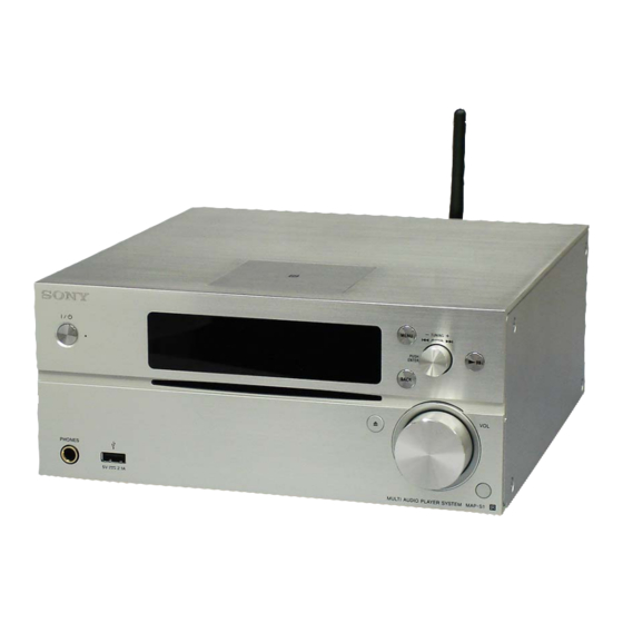
Sony MAP-S1 Service Manual
Multi audio player system
Hide thumbs
Also See for MAP-S1:
- Quick start manual (2 pages) ,
- Operating instructions manual (56 pages)
Table of Contents
Advertisement
SERVICE MANUAL
Ver. 1.0 2014.03
Note:
Be sure to keep your PC used for service and
checking of this unit always updated with the
latest version of your anti-virus software.
In case a virus affected unit was found during
service, contact your Service Headquarters.
Amplifier section
Power output (rated):
1
50 watts + 50 watts (at 4 ohms, 1 kHz)*
1
*
Measured under the following conditions:
Power requirements: 230V AC, 50Hz
(Except Canadian model)
Inputs/Outputs
LINE IN (external input) jack:
Sensitivity: 2 V
Impedance: 47 kilo ohms
LINE OUT (external output) jack:
Output voltage: 2 V
Impedance: 1 kilo ohms
5 Hz – 80 kHz (-3 dB)
PHONES (headphone) jack:
Stereo standard jack, 8 ohms or more
USB:
USB port: Type A, 5 V DC 2.1 A
DIGITAL IN jack:
USB port: Type B
CD-DA/MP3 player section
System:
Compact disc and digital audio system
Laser Diode Properties:
Emission Duration: Continuous
2
Laser Output*
: Less than 44.6 μW
2
*
This output is the value measurement at a
distance of 200mm from the objective lens
surface on the Optical Pick-up Block with 7mm
aperture.
Frequency response:
10 Hz – 20 kHz
Signal-to-noise ratio:
More than 90 dB
Dynamic range:
More than 90 dB
9-893-994-01
Sony Corporation
2014C33-1
©
2014.03
Published by Sony Techno Create Corporation
SPECIFICATIONS
Tuner section
AM tuner section:
Tuning range:
AEP, UK, Hong Kong and Malaysia models:
531 kHz-1,602 kHz (with 9 kHz tuning
interval)
Other models:
530 kHz-1,710 kHz (with 10 kHz tuning
interval)
531 kHz-1,710 kHz (with 9 kHz tuning
interval)
Antenna:
AM loop antenna
Intermediate frequency:
400 kHz
FM tuner section:
FM stereo, FM superheterodyne tuner
Tuning range:
87.5 MHz – 108.0 MHz (100 kHz step)
(Canadian model)
87.5 MHz – 108.0 MHz (50 kHz step)
(Except Canadian model)
Antenna:
FM lead antenna
Antenna terminals:
DAB/FM lead antenna
75 ohms unbalanced
DAB/DAB+ tuner section:
(Except Canadian model)
FM stereo, DAB/FM superheterodyne tuner
Frequency range:
Band-III:
3
174.928 (5A) MHz – 239.200 (13F) MHz*
Antenna:
DAB/FM lead antenna:
MAP-S1
Hong Kong Model
Model Name Using Similar Mechanism
CD Mechanism Type
Optical Pick-up Block Name
DAB/DAB+ frequency table (Band-III):
Frequency
Label
174.928 MHz
5A
176.640 MHz
5B
178.352 MHz
5C
180.064 MHz
5D
181.936 MHz
6A
183.648 MHz
6B
185.360 MHz
6C
187.072 MHz
6D
188.928 MHz
7A
190.640 MHz
7B
192.352 MHz
7C
194.064 MHz
7D
195.936 MHz
8A
197.648 MHz
8B
199.360 MHz
8C
201.072 MHz
8D
202.928 MHz
9A
204.640 MHz
9B
206.352 MHz
9C
208.064 MHz
9D
209.936 MHz
10A
211.648 MHz
10B
MULTI AUDIO PLAYER SYSTEM
Canadian Model
AEP Model
UK Model
Australian Model
Malaysia Model
NEW
CDM91A-DVBU203
CMS-S76RFS7G
Frequency
Label
213.360 MHz
10C
215.072 MHz
10D
216.928 MHz
11A
218.640 MHz
11B
220.352 MHz
11C
222.064 MHz
11D
223.936 MHz
12A
225.648 MHz
12B
227.360 MHz
12C
229.072 MHz
12D
230.784 MHz
13A
232.496 MHz
13B
234.208 MHz
13C
235.776 MHz
13D
237.488 MHz
13E
239.200 MHz
13F
3
*
Frequencies are displayed to two decimal places
on this system.
– Continued on next page –
Advertisement
Table of Contents

Related Manuals for Sony MAP-S1


Summary of Contents for Sony MAP-S1
- Page 1 10 Hz – 20 kHz 209.936 MHz Signal-to-noise ratio: 211.648 MHz – Continued on next page – More than 90 dB MULTI AUDIO PLAYER SYSTEM Dynamic range: More than 90 dB 9-893-994-01 Sony Corporation 2014C33-1 © 2014.03 Published by Sony Techno Create Corporation...
- Page 2 The BLUETOOTH® word mark and logos are registered trademarks owned by BLUETOOTH SIG, Inc. and any use of such marks by Sony Corporation is under license. The N Mark is a trademark or registered trademark of NFC Forum, Inc. in the United States and in other countries.
-
Page 3: Table Of Contents
THESE COMPONENTS WITH SONY PARTS PAR DES PIÈCES SONY DONT LES NUMÉROS SONT DON- WHOSE PART NUMBERS APPEAR AS SHOWN IN THIS NÉS DANS CE MANUEL OU DANS LES SUPPLÉMENTS MANUAL OR IN SUPPLEMENTS PUBLISHED BY SONY. PUBLIÉS PAR SONY. - Page 4 MAP-S1 SECTION 1 SERVICING NOTES NOTE OF REPLACING THE IC200, IC201, IC202 AND NOTES ON HANDLING THE OPTICAL PICK-UP IC502 ON THE MAIN BOARD BLOCK OR BASE UNIT IC200, IC201, IC202 and IC502 on the MAIN board cannot replace with single. When these parts are damaged, replace the complete The laser diode in the optical pick-up block may suffer electro- mounted board.
- Page 5 MAP-S1 TEST DISCS RELEASING THE DISC SLOT LOCK Use following TEST DISC (for CD) when this unit confi rms the The disc slot lock function for the antitheft of sample disc in the operation and checks it. shop is equipped.
- Page 6 MAP-S1 NOTE OF REPLACING THE WiFi MODULE CHECKING METHOD OF NETWORK CONNECTION When replacing the WiFi module (Ref. No. WIFI1), MAC address It is necessary to check the network connection, when replacing and DEVICE_ID are changed. Print the page 7 and page 9, cut it, the WiFi module (Ref.
- Page 7 MAP-S1 • Please cut out along the dotted line and use it. Note of the MAC address change: Note of the MAC address change: The MAC address of this unit was changed along with this repair. The MAC address of this unit was changed along with this repair.
- Page 8 MAP-S1 MEMO...
- Page 9 Please refer to the Operating Instructions “Listening to music on Win- Please refer to the Operating Instructions “Listening to music on Win- dows 8/Windows 7 (Home network)” or SONY Support site for the dows 8/Windows 7 (Home network)” or SONY Support site for the re-setup method.
- Page 10 MAP-S1 MEMO...
- Page 11 MAP-S1 HOW TO EJECT THE DISC WHEN POWER SWICTH TURN OFF • Refer to “SECTION 2. DISASSEMBLY”, remove the CD mechanism deck block from the unit 1 tape 3 Take out the disc. 2 Rotate the pulley in the direction of the arrow.
-
Page 12: Disassembly
MAP-S1 SECTION 2 DISASSEMBLY • This set can be disassembled in the order shown below. 2-1. DISASSEMBLY FLOW 2-2. PANEL (SIDE L/R) (Page 13) 2-3. PANEL (FRONT) BLOCK-1 (Page 13) 2-4. PANEL (FRONT) BLOCK-2 (Page 14) 2-5. BRACKET JACK BLOCK 2-9. -
Page 13: Panel (Side L/R)
MAP-S1 Note: Follow the disassembly procedure in the numerical order given. 2-2. PANEL (SIDE L/R) 1 two screws 4 panel (side L) (flat head) 1 two screws (flat head) 3 two claws 4 panel (side R) 2 Remove the panel (side L) in the direction of the arrow. -
Page 14: Panel (Front) Block-2
MAP-S1 2-4. PANEL (FRONT) BLOCK-2 sleeve ferrite clamp (FC1) HP board 1 Remove the panel (front) block in the direction of an arrow. coating clip FRONT-L board 2 Remove the wire from the coating clip. 3 connector (CN4005) 4 connector... -
Page 15: Bracket Jack Block
MAP-S1 2-5. BRACKET JACK BLOCK hole 1 flexible flat cable (5P) (CN4004) 4 Draw out two jacks from two holes. 2 screw (BVTP2.6) 2 screw (BVTP2.6) 5 bracket jack block (Except Canadian) 2 screw 3 coating (BVTP2.6) clip – Panel (front) rear bottom view –... -
Page 16: Front-Eject Board, Front-L Board
MAP-S1 2-7. FRONT-EJECT BOARD, FRONT-L BOARD 3 flexible flat cable (19P) (CN4805) qa boss 2 flexible flat cable (14P) (CN4801) qa boss 1 flexible flat cable (8P) (CN4802) 7 flexible flat cable (5P) (CN4804) qs FRONT-L board 0 screw (BVTP2.6) 0 screw (BVTP2.6) -
Page 17: Holder Bt Nfc Block
MAP-S1 2-9. HOLDER BT NFC BLOCK 2 flexible flat cable (14P) (CN4801) cushion (BT FFC) 3 flexible flat cable (8P) (CN4802) 1 cushion 5 holder BT NFC block (BT FFC) 4 screw (BTP2.6 Note 1: Arrange so that two flexible flat cables 4 screw do not come out outside this line. -
Page 18: Cd Mechanism Deck Block
MAP-S1 2-10. CD MECHANISM DECK BLOCK 1 filament tape 2 connector (sub material) (CN4201) filament tape (sub material) CD mechanism deck 3 four screws (BV3) – – Note 1: Insert the connector straight into the interior. There is a possibility that using this device without the connector correctly installed will damage it. -
Page 19: Cd Mechanism Deck (Cdm91A-Dvbu203)
MAP-S1 2-11. CD MECHANISM DECK (CDM91A-DVBU203) 3 CD mechanism deck 1 two screws (CDM91A-DVBU203) (BV/ring) 1 two screws (BV/ring) 2 bracket CDM 2-12. FFC GUIDE 1 filament tape le ible lat cable settin (sub material) cut end filament tape (sub material) -
Page 20: Bottom Cover (I)
MAP-S1 2-13. BOTTOM COVER (I) 1 claw 2 two claws – CD mechanism deck block bottom view – 3 cover sheet 4 two screws (PTP2 4 two screws (PTP2 5 bottom cover (I) -
Page 21: Optical Pick-Up Block (Cms-S76Rfs7G) (Op1)
MAP-S1 2-14. OPTICAL PICK-UP BLOCK (CMS-S76RFS7G) (OP1) r e i bottom side short insulator long 4 flexible flat cable (24P) 6 insulator (FFC9) top side 7 optical pick-up block (CMS-S76RFS7G) (OP1) 6 insulator 2 float screw (S) 6 insulator 5 connector 2 float 1 Remove the wire from three claws. -
Page 22: Tuner Board Block
MAP-S1 2-15. TUNER BOARD BLOCK 4 TUNER board block 1 flexible flat cable (9P) (CN002) Note 1: When installing the flexible flat 2 two screws cable (9P), check the terminal side (BV/ring) terminal not to mistake a direction. side 3 Remove the TUNER board block in the direction of the arrow. -
Page 23: Tuner Board
MAP-S1 2-16. TUNER BOARD flexible guide line 2 lower cushion flat (antenna) cable TUNER (9P) board flexible flat cable (9P) lower cushion (antenna) ferrite core (FC3) ferrite core binding band (FC3) 3 flexible flat cable (9P) (taiton) (CN101) 6 TUNER... -
Page 24: Dab Board Block (Except Canadian Model)
MAP-S1 2-17. DAB BOARD BLOCK (Except Canadian model) 5 DAB board block Note 2: When installing the flexible flat cable, ensure that the colored line is parallel to the connector after insertion. 1 flexible flat cable (9P) (CN012) 2 nut Note 1: When installing the flexible flat Insert straight into the interior. -
Page 25: Panel Back Block
MAP-S1 2-19. PANEL BACK BLOCK Note 1: Insert the connector straight into the interior. There is a possibility that using this device 1 three screws without the connector correctly installed will (BV3) damage it. Insert straight into the interior. connector connector –... -
Page 26: Antenna 2.4 Ghz (Ant1), Holder (Antenna)
MAP-S1 2-20. ANTENNA 2.4 GHz (ANT1), HOLDER (ANTENNA) Note: When the WiFi antenna (Ref. No. ANT1) is replaced, refer to “CHECKING METHOD OF NETWORK CONNECTION” on page 6. 1 antenna connector 3 screw (CON2) 2 antenna 2.4 GHz (BV/ring) (ANT1) -
Page 27: Wifi Module (Wifi1), Network Board
MAP-S1 2-22. WiFi MODULE (WIFI1), NETWORK BOARD Note 1: When the WiFi module (Ref. No. WIFI1) is replaced, refer to “NOTE OF REPLACING THE WiFi MODULE”, “PROCESS- ING OF REPLACING THE WiFi MODULE” and “CHECKING METHOD OF NETWORK CONNECTION” on page 6. -
Page 28: Ac Inlet (2P) (Ac1)
MAP-S1 2-23. AC INLET (2P) (AC1) [gray] AC inlet (2P) (AC1) [white] 4 claw 5 AC inlet (2P) (AC1) 4 claw Note: During reassembly, use new binding band (taiton) to fasten the wires back in place as they were before disassembly. -
Page 29: Amp Board Block
MAP-S1 2-24. AMP BOARD BLOCK Note 1: When installing the AMP board block, check that two claws are attached firmly. 2 claw 1 four screws (BV3) Wire e i flexible flat cable (9P) AMP board 2 claw 6 connector (CN2003) -
Page 30: Amp Board
MAP-S1 2-25. AMP BOARD Note: When installing the flexible flat cable, ensure that the colored line is parallel to the connector after insertion. Insert at a slant. Insert straight into the interior. flexible flat flexible flat cable cable colored line... -
Page 31: Main Board
MAP-S1 2-26. MAIN BOARD setting 5 connector (CN703) 1 flexible flat cable (23P) main trans POWER board (CN006) 4 connector (CN702) 2 flexible flat cable (26P) (CN008) 3 Remove the wire from the coating clip. coating clip MAIN board Wire touches the main trans. -
Page 32: Power Board
MAP-S1 2-27. POWER BOARD 2 connector (CN5001) main trans 4 three screws (BV3) 4 screw (BV3) 8 POWER board 5 coating clip 1 Remove the wires from the lead pin. coating clip lead pin POWER board 6 Remove the POWER... -
Page 33: Test Mode
MAP-S1 SECTION 3 TEST MODE 1. TEST MODE BY THE MAIN UNIT OPERATION 1-3. AM step change mode It operate the test mode by the main unit. (Canadian and Australian models) Either the 9 kHz step or 10 kHz step can be selected for the AM 1-1. - Page 34 MAP-S1 1-5. RF Mode 4. When the [– TUNING + ] dial turned clockwise/ . > counterclockwise, the message is changed with “Volume Min” It can turn on and off the wireless signal of WiFi and Bluetooth. ↔ “Volume 1” ↔ “Volume 18” ↔ “Volume Max” on the fl uores- cent indicator tube and volume setting is changed.
- Page 35 STEREO (Version is not displayed) 0.12 tinues blinking on the liquid crystal display) STEREO CDMA version Screen display STEREO CDMA 1.43 NWM version STEREO MAP-S1 B STEREO 1.01 CDMB version STEREO CDMB 0.10 BTM version Blinking STEREO 40.00 ST version STEREO 1.39...
- Page 36 MAP-S1 7. When pressing the [ ] button on the remote commander while 2-4. WiFi Reception Level the each version is displayed, year, month and day of the soft- It can display the reception level at the time of wireless LAN con- ware creation is displayed.
- Page 37 MAP-S1 2-5. Auto Standby Test It can confi rm the auto standby function operates normally. The auto standby function operates in 60 seconds in this mode. (Usually, it takes 15 minutes) Procedure: 1. Press the [ ] button to turn the power on.
-
Page 38: Electrical Checks
MAP-S1 SECTION 4 ELECTRICAL CHECKS 6. Servo check is started, following screen is displayed on the 0 dB = 1 V TUNER SECTION fl uorescent indicator tube. FM TUNE LEVEL CHECK Servo check start signal generator unit Procedure: 1. Press the [ ] button to turn the power on. -
Page 39: Diagrams
MAP-S1 SECTION 5 DIAGRAMS 5-1. BLOCK DIAGRAM - CD/USB Section - OPTICAL PICK-UP BLOCK RF AMP, SERVO/AUDIO PROCESSOR I2S_DIN_MTK, I2S_DOUT_MTK, (CMS-S76RFS7G) IC503 I2S_BCK_MTK, I2S_LRCK_MTK, MCK-MTK I2S_DIN_MTK >001B 123 RFIP ASDATA0 I2S_BCK_MTK ABCK (Page 40) VOA/A 1 RF_C I2S_LRCK_MTK ALRCK VOB/B... -
Page 40: Block Diagram - Audio Section
MAP-S1 5-2. BLOCK DIAGRAM - AUDIO Section - DATA SELECTOR AUDIO DSP, SYSTEM CONTROLLER I2S_DIN_MTK, I2S_DOUT_MTK, IC903 IC203 (2/4) I2S_BCK_MTK, I2S_LRCK_MTK, I2S0_DO, MCK-MTK I2S_DIN_MTK >001B I2S2_DO 11 3A I2S0_DO >005B NET-DATA 55 I2S_DI_MTK/BCO I2S_DO_DAC 10 3B I2S2_DO (Page 39) I2S_BCK_MTK... -
Page 41: Block Diagram - Amp Section
MAP-S1 5-3. BLOCK DIAGRAM - AMP Section - DIGITAL AUDIO/CLOCK SIGNAL SELECTOR D/A CONVERTER TONE CONTROL, INPUT SELECTOR, IC910 IC913 I2S0_DO, ELECTRICAL VOLUME DIGITAL AUDIO AMP I2S2_DO IC2001 I2S0_DO IC2003 >005B 14 4A TB2001 DATA IOUTL+ 13 4B BOOSTER DAC LPF... -
Page 42: Block Diagram - Panel/Power Supply Section
MAP-S1 5-4. BLOCK DIAGRAM - PANEL/POWER SUPPLY Section - REMOTE CONTROL RECEIVER 135 SIRCS_IN IC3520 A5.2V 40 SPI_DO_FL D5.2V ND4401 35 SPI_CLK_FL FLUORESCENT FE5.2V INDICATOR 38 SPI_CS_FL RESET_FL TUBE +1.2V +1.2V REGULATOR IC501 +3.3V +3.3V REGULATOR IC505 RECT D4404, 4406... - Page 43 MAP-S1 THIS NOTE IS COMMON FOR PRINTED WIRING BOARDS AND SCHEMATIC DIAGRAMS. • Circuit Boards Location (In addition to this, the necessary note is printed in each block.) For Printed Wiring Boards. For Schematic Diagrams. FRONT-KEY board Note: Note: • All capacitors are in μF unless otherwise noted. (p: pF) 50 •...
-
Page 44: Printed Wiring Boards - Main Section (1/2) (Suffi X-11: Canadian Model Only)
MAP-S1 5-5. PRINTED WIRING BOARDS - MAIN Section (1/2) (Suffi x-11: Canadian model only) - • See page 43 for Circuit Boards Location. • : Uses unleaded solder. ANTENNA FM 75 COAXIAL TUNER (Page 58) BOARD >08P BOARD CN4005 MAIN BOARD... -
Page 45: Printed Wiring Board - Main Section (2/2) (Suffi X-11: Canadian Model Only)
MAP-S1 5-6. PRINTED WIRING BOARD - MAIN Section (2/2) (Suffi x-11: Canadian model only) - • See page 43 for Circuit Boards Location. • : Uses unleaded solder. MAIN BOARD (SIDE B) R069 R070 D709 C956 IC918 C955 Q705 D707... -
Page 46: Printed Wiring Boards - Main Section (1/2) (Suffi X-12)
MAP-S1 5-7. PRINTED WIRING BOARDS - MAIN Section (1/2) (Suffi x-12) - • See page 43 for Circuit Boards Location. • : Uses unleaded solder. ANTENNA DAB 75 ANTENNA FM 75 COAXIAL DAB1 MODULE (DAB TUNER) TUNER (Page 58) BOARD >23P... -
Page 47: Printed Wiring Board - Main Section (2/2) (Suffi X-12)
MAP-S1 5-8. PRINTED WIRING BOARD - MAIN Section (2/2) (Suffi x-12) - • See page 43 for Circuit Boards Location. • : Uses unleaded solder. MAIN BOARD (SIDE B) R069 R070 D709 C956 IC918 C955 Q705 D707 C957 C954 R1019... -
Page 48: Schematic Diagram - Main Section (1/7)
MAP-S1 5-9. SCHEMATIC DIAGRAM - MAIN Section (1/7) - • See page 74 for Waveforms. • See page 75 for IC Block Diagrams. • See page 82 for IC Pin Function Description. MAIN BOARD (1/7) IC501 +1.2V REGULATOR IC501 MM1701CHBE... -
Page 49: Schematic Diagram - Main Section (2/7)
MAP-S1 5-10. SCHEMATIC DIAGRAM - MAIN Section (2/7) - • See page 75 for IC Block Diagrams. MAIN BOARD (2/7) CL864 C868 R867 R876 R878 R879 R880 R881 R883 C872 R884 SL855 SL856 IC851 R865 DC/DC CONVERTER (3.2) (3.1) IC851 CL507 (3.2) -
Page 50: Schematic Diagram - Main Section (3/7)
MAP-S1 5-11. SCHEMATIC DIAGRAM - MAIN Section (3/7) - • See page 75 for IC Block Diagrams. MAIN BOARD (3/7) (Page 51) >115S BCO-1.2VP-ON AC_RELAY MAIN (Page 51) >111S D001 BOARD MAIN BUS1 DA2J10100L (4/7) BOARD DGND (4/7) MAIN (Page 52) >116S... -
Page 51: Schematic Diagram - Main Section (4/7)
MAP-S1 5-12. SCHEMATIC DIAGRAM - MAIN Section (4/7) - • See page 75 for IC Block Diagrams. MAIN BOARD (4/7) >111S BUS1 DGND R247 MAIN R321 R325 R329 R333 R337 R339 R341 R343 C200 BOARD BCO-1.2VP-ON FL_CLK SPI1_CLK R260 0.01... -
Page 52: Schematic Diagram - Main Section (5/7)
MAP-S1 5-13. SCHEMATIC DIAGRAM - MAIN Section (5/7) - • See page 74 for Waveforms. • See page 75 for IC Block Diagrams. MAIN BOARD (5/7) MAIN >118S BOARD BUS6 (4/7) (Page 51) MAIN >112S BOARD BUS2 (3/7) (Page 50) -
Page 53: Schematic Diagram - Main Section (6/7)
MAP-S1 5-14. SCHEMATIC DIAGRAM - MAIN Section (6/7) - • See page 74 for Waveforms. • See page 75 for IC Block Diagrams. • See page 82 for IC Pin Function Description. MAIN BOARD (6/7) CN202 JL214 MD BOOT1 R420... -
Page 54: Schematic Diagram - Main Section (7/7)
MAP-S1 5-15. SCHEMATIC DIAGRAM - MAIN Section (7/7) - • See page 74 for Waveforms. • See page 75 for IC Block Diagrams. MAIN BOARD (7/7) L703 C723 CN702 10uH IC703 CL701 R719 Ever3.3V CL702 DC/DC CONVERTER JC705 Ever1.7V IC703... -
Page 55: Schematic Diagram - Network Board
MAP-S1 5-16. SCHEMATIC DIAGRAM - NETWORK Board - • See page 75 for IC Block Diagrams. ANT1 NETWORK BOARD (WiFi ANTENNA) WIFI1 WIFI MODULE CN3001 120P JC3008 C3019 JC3017 JC3019 IC3002 0.047 CL3067 10 1V2 +1.2V REGULATOR JC3018 C3012 C3014... -
Page 56: Printed Wiring Board - Network Board (Suffi X-11: Canadian Model Only)
MAP-S1 5-17. PRINTED WIRING BOARD - NETWORK Board (Suffi x-11: Canadian model only) - • See page 43 for Circuit Boards Location. • : Uses unleaded solder. MAIN NETWORK BOARD (COMPONENT SIDE) NETWORK BOARD (Page 44) (CONDUCTOR SIDE) >01P BOARD... -
Page 57: Printed Wiring Board - Network Board (Suffi X-12)
MAP-S1 5-18. PRINTED WIRING BOARD - NETWORK Board (Suffi x-12) - • See page 43 for Circuit Boards Location. • : Uses unleaded solder. MAIN NETWORK BOARD (COMPONENT SIDE) NETWORK BOARD (Page 46) (CONDUCTOR SIDE) >16P BOARD CN003 FFC13 CN3002... -
Page 58: Printed Wiring Boards - Usb/Hp Boards
MAP-S1 5-19. PRINTED WIRING BOARDS - USB/HP Boards - • See page 43 for Circuit Boards Location. • : Uses unleaded solder. (Suffix-11) (Suffix-11) >08P >09P MAIN NETWORK BOARD BOARD CN701 CN3009 (Page 44) (Page 56) >23P >24P MAIN NETWORK... -
Page 59: Schematic Diagram - Usb/Hp Boards
MAP-S1 5-20. SCHEMATIC DIAGRAM - USB/HP Boards - • See page 75 for IC Block Diagrams. USB BOARD HP BOARD CN4004 JL4004 POWER_USB FFC3 JC4201 JL4003 (Page 62) ILIM_CHANGE CN4201 JL4002 >10S (Page 63) USB_OC C4203 JL4201 JC4203 0.01 >11S... -
Page 60: Printed Wiring Board - Front-L Board (Suffi X-11: Canadian Model Only)
MAP-S1 5-21. PRINTED WIRING BOARD - FRONT-L Board (Suffi x-11: Canadian model only) - • See page 43 for Circuit Boards Location. • : Uses unleaded solder. FRONT (Page 68) >12P BOARD CN4401 FFC5 CL4857 CN4805 CL4852 CL4853 CL4847 CL4851... -
Page 61: Printed Wiring Board - Front-L Board (Suffi X-12)
MAP-S1 5-22. PRINTED WIRING BOARD - FRONT-L Board (Suffi x-12) - • See page 43 for Circuit Boards Location. • : Uses unleaded solder. FRONT (Page 68) >27P BOARD CN4401 FFC5 CL4857 CN4805 CL4852 CL4853 CL4847 CL4851 CL4850 CL4848 FRONT-L BOARD... -
Page 62: Schematic Diagram - Front-L Board
MAP-S1 5-23. SCHEMATIC DIAGRAM - FRONT-L Board - FRONT-L BOARD CN4804 CN4803 R4805 CL4824 FFC3 POWER_USB POWER_USB (Page 59) CL4823 R4806 ILIM_CHANGE ILIM_CHANGE CL4822 >10S USB_OC USB OC CL4821 R4807 R4816 VBUS-GND NFC_SPICLK CL4839 BOARD VBUS-GND NFC SPICLK R4817 CL4840... -
Page 63: Schematic Diagram - Amp Board
MAP-S1 5-24. SCHEMATIC DIAGRAM - AMP Board - • See page 75 for IC Block Diagrams. AMP BOARD ET2003 J2001 LINE IN LINE OUT C2044 C2047 C2046 C2043 C2048 C2045 4700 0.001 4700 0.001 Q2012, 2703, 2903 (CHASSIS) R2717 PROTECT DETECT... -
Page 64: Printed Wiring Board - Amp Board (Component Side) (Suffi X-11: Canadian Model Only)
MAP-S1 5-25. PRINTED WIRING BOARD - AMP Board (Component Side) (Suffi x-11: Canadian model only) - • See page 43 for Circuit Boards Location. • : Uses unleaded solder. MAIN >04P (Page 44) BOARD CN010 AMP BOARD (COMPONENT SIDE) (CHASSIS) -
Page 65: Printed Wiring Board - Amp Board (Conductor Side) (Suffi X-11: Canadian Model Only)
MAP-S1 5-26. PRINTED WIRING BOARD - AMP Board (Conductor Side) (Suffi x-11: Canadian model only) - • See page 43 for Circuit Boards Location. • : Uses unleaded solder. MAIN (Page 44) >03P BOARD AMP BOARD (CONDUCTOR SIDE) CN009 IC2008... -
Page 66: Printed Wiring Board - Amp Board (Component Side) (Suffi X-12)
MAP-S1 5-27. PRINTED WIRING BOARD - AMP Board (Component Side) (Suffi x-12) - • See page 43 for Circuit Boards Location. • : Uses unleaded solder. MAIN (Page 46) >19P BOARD CN010 AMP BOARD (COMPONENT SIDE) (CHASSIS) FFC10 CN2001 JC2028... -
Page 67: Printed Wiring Board - Amp Board (Conductor Side) (Suffi X-12)
MAP-S1 5-28. PRINTED WIRING BOARD - AMP Board (Conductor Side) (Suffi x-12) - • See page 43 for Circuit Boards Location. • : Uses unleaded solder. MAIN (Page 46) >18P BOARD AMP BOARD (CONDUCTOR SIDE) CN009 IC2008 IC2007 CL2056 JC2033... -
Page 68: Printed Wiring Board - Front Board
MAP-S1 5-29. PRINTED WIRING BOARD - FRONT Board - • See page 43 for Circuit Boards Location. • : Uses unleaded solder. T4401 S4401 FRONT BOARD C4411 JC4401 L4401 CL4421 JW4411 Q4403 Q4404 CL4418 T4401 DC/DC C4408 CL4428 CONVERTER CL4423... -
Page 69: Schematic Diagram - Front Board
MAP-S1 5-30. SCHEMATIC DIAGRAM - FRONT Board - • See page 74 for Waveforms. FRONT BOARD ND4401 FLUORESCENT INDICATOR TUBE JC4414 CN4401 C4417 JC4407 D_GND CL4407 FL_CS CL4408 JC4408 FL_CLK CL4409 JC4410 0 FL_RESET CL4410 FL_DATA JC4409 D_GND L4401 C4419... -
Page 70: Schematic Diagram - Key Section
MAP-S1 5-31. SCHEMATIC DIAGRAM - KEY Section - FRONT-R BOARD IC3520 REMOTE CONTROL RECEIVER FRONT-KEY BOARD IC3520 PNA4823M03S0 JC3516 CN3521 CN3510 JC3512 JC3522 CL3513 JOG_FUNCTION JC3523 CL3527 CL3512 JC3513 R3512 KEY2 KEY1 JC3524 CL3528 CL3511 KEY1 KEY2 JC3525 CL3529 CL3510... -
Page 71: Printed Wiring Boards - Key Section
MAP-S1 5-32. PRINTED WIRING BOARDS - KEY Section - • See page 43 for Circuit Boards Location. • : Uses unleaded solder. FRONT-R BOARD (COMPONENT SIDE) FRONT-KEY BOARD EN3510 – TUNING + S3511 MENU PUSH ENTER EN3510 FRONT-EJECT BOARD (COMPONENT SIDE) -
Page 72: Printed Wiring Board - Subpower Board
MAP-S1 5-33. PRINTED WIRING BOARD - SUBPOWER Board - • See page 43 for Circuit Boards Location. • : Uses unleaded solder. SUBPOWER BOARD CL5001 C5005 ~AC IN CN5002 T5001 T5002 LINE FILTER SUB POWER TRANSFORMER D5007 C5011 CL5002 D5009... -
Page 73: Schematic Diagram - Subpower Board
MAP-S1 5-34. SCHEMATIC DIAGRAM - SUBPOWER Board - MAIN POWER SUBPOWER BOARD TRANSFORMER (Page 63) >15S BOARD F5001 D5001 T4AL CN2003 VH– 11EQS04-TB5 250V CN5001 D5002 11EQS04-TB5 C5001 C5003 C5004 3300 VL– C5002 VL– D5003 11EQS04-TB5 NOT REPLACEABLE: BUILT IN TRANSFORMER... - Page 74 MAP-S1 • Waveforms – MAIN Board – – MAIN Board – – FRONT Board – IC503 8 (XTALO) IC907 3 (CLK-OUT) IC203 e; (I2S_LRCK_DAC) IC203 <zv/ (USB_X2) Q4403, 4404 (Base) 3.7 Vp-p 3.5 Vp-p 1.3 Vp-p 3.9 Vp-p 1.1 Vp-p 44.4 ns...
- Page 75 MAP-S1 • IC Block Diagrams – MAIN Board – IC001 MM3526A33NRE VDD 1 GND 2 VOUT THERMAL CURRENT SHUTDOWN LIMIT VREF CE 3 BIAS IC201 TCA6424ARGJR GND 25 ADDR 26 VCCP 27 POWER-ON RESET RESET 28 24 Bits SCL 29...
- Page 76 MAP-S1 IC505, 709 MM3374A33PRE VOUT CE 1 BIAS THERMAL CURRENT VOLTAGE SHUTDOWN LIMIT REFERENCE GND 2 NC 3 IC701 – 704 TPS54332CDDAR 8 PH 7 GND BOOT MAXIMUM BOOT 1 6 COMP UNDERVOLTAGE CLAMP LOCKOUT BOOT THERMAL CHARGE SHUTDOWN DISCHARGE...
- Page 77 MAP-S1 IC851 BD00GA3WEFJ-E2 IC852 AM5890S MUTE MUTE BIAS VINFC 1 VINTK SOFT TRB1 2 REGO2 3 TRB2 VOLTAGE RESET DETECTION VINSL+ 4 VINLD REGO1 5 VCTL VCCD FWD 6 VCC2 DRIVER REV 7 VCC2 SPINDLE VOLD– VCC1 DRIVER (4x) VCC2...
- Page 78 MAP-S1 IC907 CS230002-CZZR VD 1 GND 2 OUT_EN CLK_OUT 3 FRACTIONAL-N FILTN FREQUENCY FILTP SYNTHESIZER LOCK 4 M [1:0] OUTPUT TO INPUT 00 = 1 CLOCK RADIO 128 Hz BW DIGITAL PLL 01 = 2 & FRACTIONAL N LOGIC 10 = 4...
- Page 79 MAP-S1 IC914 PCM1754DBQR SYSTEM SYSTEM CLOCK 16 SCK CLOCK MANAGER AUDIO SERIAL DATA MUTE SERIAL CONTROL PORT PORT LRCK 13 DEMP DGND POWER 4x/8x OVERSAMPLING DIGITAL SUPPLY FILTER & FUNCTION CONTROL 12 TEST ENHANCED MULTILEVEL ZERO 11 ZEROA DELTA-SIGMA MODULATOR...
- Page 80 MAP-S1 – NETWORK Board – IC3001 FSUSB63UMX HSD3 HSD3 HSD1 HSD1 SELECTOR SEL [1] 11 SEL [0] VCC 12 IC3002 S-13A1A12-E6T1U3 VOUT 1 OVERCURRENT PROTECTION THERMAL SHUTDOWN ON/OFF – CONTROL REFERENCE VOLTAGE VSS 2 ON/OFF 3 INRUSH CURRENT LIMITING – USB Board –...
- Page 81 MAP-S1 – AMP Board – IC2001 NJW1194 INA1 1 INB1 INA2 2 INB2 INA3 3 INB3 INA4 4 INB4 GND 5 DCCAP_A 6 DCCAP_B GND 7 OUTA 8 OUTB VDDOUT 9 DATA 10 ADR1 CONTROL CLOCK 11 ADR0 LOGIC LATCH 12 V–...
- Page 82 MAP-S1 • IC Pin Function Description MAIN BOARD IC203 R7S7200032CFP (AUDIO DSP, SYSTEM CONTROLLER) Pin No. Pin Name Description RDS_INT RDS interrupt signal input from the TUNER board SPI_CLK_BCO Serial data transfer clock signal output to the WiFi module SPI_CS_BCO...
- Page 83 MAP-S1 Pin No. Pin Name Description KEY_WAKEUP Power key input terminal USB_OVER_ USB VBUS power over current detection signal input terminal CURRENT D1.18V_SOC Power supply terminal (+1.18V) CDM_UNLOAD_ Unloading end detection switch input terminal END_SW CDM_LOAD_SW Loading detection switch input terminal...
- Page 84 MAP-S1 Pin No. Pin Name Description UART_TxD_DEBUG Serial data output terminal for fl ash writing Not used DGND Ground terminal UART_RxD_DEBUG Serial data input terminal for fl ash writing Not used LED_GREEN LED drive signal output terminal for the standby indicator “L”: LED on...
- Page 85 MAP-S1 Pin No. Pin Name Description D3.3V_SOC Power supply terminal (+3.3V) RESET_IOEX Reset signal output to the I/O expander “L”: reset CDM_LOAD_ Loading end detection switch input terminal END_SW...
- Page 86 MAP-S1 MAIN BOARD IC503 CXD90013R (RF AMP, SERVO/AUDIO PROCESSOR) Pin No. Pin Name Description RF_C RF main beam (A) input from the optical pick-up block RF_D RF main beam (D) input from the optical pick-up block RF_E RF sub beam (F) input from the optical pick-up block...
- Page 87 MAP-S1 Pin No. Pin Name Description RWE# Write enable signal output to the SD-RAM DVSS12 Ground terminal (digital system) CAS# Column address strobe signal output to the SD-RAM RAS# Row address strobe signal output to the SD-RAM DVDD33 Power supply terminal (+3.3V) (digital system)
-
Page 88: Exploded Views
MAP-S1 SECTION 6 EXPLODED VIEWS Note: • -XX and -X mean standardized parts, so • Color Indication of Appearance Parts Ex- The components identifi ed by mark 0 they may have some difference from the ample: or dotted line with mark 0 are critical for original one. -
Page 89: Bracket Cdm Section
MAP-S1 6-2. BRACKET CDM SECTION CD mechanism deck section not supplied FRONT-L board section (AEP, UK, AUS, HK, FFC1 AMP board section FFC2 Ref. No. Part No. Description Remark Ref. No. Part No. Description Remark 3-704-515-22 SCREW (BV/RING) FFC1 9-885-194-29 FY14 FFC (1.0 mm_23P_JOINT) -
Page 90: Front-L Board Section
MAP-S1 6-3. FRONT-L BOARD SECTION • Rear bottom view not supplied not supplied supplied with not supplied EN3521 (HP board) panel (front) section not supplied (AEP, UK, AUS, HK, not supplied not supplied (FRONT-L board) FFC3 EN3521 not supplied FFC4... -
Page 91: Panel Front Section
MAP-S1 6-4. PANEL FRONT SECTION • Rear bottom view FFC7 not supplied NFC1 FFC6 FFC5 not supplied not supplied ND4401 not supplied not supplied not supplied (FRONT board) Ref. No. Part No. Description Remark Ref. No. Part No. Description Remark 3-087-053-01 +BVTP2.6 (3CR) -
Page 92: Cd Mechanism Deck Section (Cdm91A-Dvbu203)
MAP-S1 6-5. CD MECHANISM DECK SECTION (CDM91A-DVBU203) CDM1 not supplied FFC8 optical pick-up section Ref. No. Part No. Description Remark Ref. No. Part No. Description Remark 4-451-680-01 FFC GUIDE CDM1 A-1990-245-A LOADING ASSY 4-464-704-01 SHEET, COVER (Including MS-091 board, loading motor) -
Page 93: Optical Pick-Up Section
MAP-S1 6-6. OPTICAL PICK-UP SECTION FFC9 not supplied Ref. No. Part No. Description Remark Ref. No. Part No. Description Remark 4-456-402-01 INSULATOR 0 OP1 A-1940-584-A OPTICAL PICK-UP BLOCK (CMS-S76RFS7G) 4-418-987-01 SHEET (S76) (for SERVICE) (Including sled motor, spindle motor) FFC9 9-885-194-18 FY14 FFC (0.5 mm_24P_OP) -
Page 94: Amp Board Section
MAP-S1 6-7. AMP BOARD SECTION not supplied 302 302 FFC10 – Rear view – not supplied not supplied not supplied tuner section G M N not supplied chassis section Ref. No. Part No. Description Remark Ref. No. Part No. Description... -
Page 95: Tuner Section
MAP-S1 6-8. TUNER SECTION not supplied FFC11 back panel section DAB1 (CND) FFC12 354 354 not supplied (AEP, UK, AUS, HK, MY) – Rear view – Ref. No. Part No. Description Remark Ref. No. Part No. Description Remark A-1990-335-A TUNER BOARD, COMPLETE... -
Page 96: Back Panel Section
MAP-S1 6-9. BACK PANEL SECTION WIFI1 not supplied (CND) not supplied ANT1 not supplied not supplied not supplied FFC13 not supplied not supplied – Rear view – Note 1: When the WiFi antenna (Ref. No. ANT1) is replaced, refer to “CHECKING METHOD OF NETWORK CONNECTION”... -
Page 97: Chassis Section
MAP-S1 6-10. CHASSIS SECTION not supplied 453 453 not supplied not supplied not supplied not supplied not supplied not supplied not supplied Ref. No. Part No. Description Remark Ref. No. Part No. Description Remark A-2042-293-A MAIN BOARD, COMPLETE (for SERVICE) (CND) -
Page 98: Electrical Parts List
MAP-S1 SECTION 7 ELECTRICAL PARTS LIST Note: • Due to standardization, replacements in • CAPACITORS When indicating parts by reference num- the parts list may be different from the uF: μF ber, please include the board name. parts specifi ed in the diagrams or the com- •... - Page 99 MAP-S1 Ref. No. Part No. Description Remark Ref. No. Part No. Description Remark C2925 1-118-289-11 CERAMIC CHIP 0.1uF JC2012 1-216-864-11 SHORT CHIP C2926 1-162-968-91 CERAMIC CHIP 0.0047uF JC2013 1-216-864-11 SHORT CHIP C2927 1-137-190-91 FILM 0.22uF JC2016 1-216-864-11 SHORT CHIP C2928...
- Page 100 MAP-S1 FRONT Ref. No. Part No. Description Remark Ref. No. Part No. Description Remark R2027 1-216-821-11 METAL CHIP 1/10W R2934 1-216-845-11 METAL CHIP 100K 1/10W (Suffi x-12) (See Note) R2935 1-216-845-11 METAL CHIP 100K 1/10W R2703 1-216-206-00 RES-CHIP 2.2K 1/8W...
- Page 101 MAP-S1 FRONT FRONT-EJECT FRONT-KEY FRONT-L Ref. No. Part No. Description Remark Ref. No. Part No. Description Remark D4403 6-502-945-01 DIODE CRH01 (TE85R, Q) < TRANSFORMER > D4404 6-503-856-01 DIODE PMEG3010EJ D4405 6-502-945-01 DIODE CRH01 (TE85R, Q) T4401 1-697-345-11 DC/DC CONV. TRANS.
- Page 102 MAP-S1 FRONT-L FRONT-R MAIN Ref. No. Part No. Description Remark Ref. No. Part No. Description Remark C4808 1-116-705-11 CERAMIC CHIP 47uF < JUMPER RESISTOR > C4810 1-118-289-11 CERAMIC CHIP 0.1uF JC3522 1-216-864-11 SHORT CHIP C4812 1-118-361-11 CERAMIC CHIP 0.1uF JC3523...
- Page 103 MAP-S1 MAIN Ref. No. Part No. Description Remark Ref. No. Part No. Description Remark C011 1-116-100-11 ELECT CHIP 220uF 6.3V C512 1-112-692-11 CERAMIC CHIP 1000PF * C015 1-116-720-11 CERAMIC CHIP 10uF 6.3V C513 1-112-692-11 CERAMIC CHIP 1000PF C016 1-164-874-11 CERAMIC CHIP 100PF...
- Page 104 MAP-S1 MAIN Ref. No. Part No. Description Remark Ref. No. Part No. Description Remark C704 1-118-391-11 CERAMIC CHIP 0.01uF C852 1-118-386-11 CERAMIC CHIP 0.1uF * C705 1-118-466-11 CERAMIC CHIP 4.7uF C854 1-165-492-21 ELECT CHIP 100uF * C706 1-118-466-11 CERAMIC CHIP 4.7uF...
- Page 105 MAP-S1 MAIN Ref. No. Part No. Description Remark Ref. No. Part No. Description Remark C952 1-124-779-00 ELECT CHIP 10uF FB006 1-481-746-11 SDM EMI FERRITE C953 1-124-779-00 ELECT CHIP 10uF FB007 1-481-746-11 SDM EMI FERRITE C954 1-127-967-21 FILM CHIP 0.0022uF FB008...
- Page 106 MAP-S1 MAIN Ref. No. Part No. Description Remark Ref. No. Part No. Description Remark JC701 1-216-864-11 SHORT CHIP R014 1-218-941-81 METAL CHIP 1/16W JC702 1-216-864-11 SHORT CHIP R015 1-218-941-81 METAL CHIP 1/16W JC703 1-216-864-11 SHORT CHIP JC704 1-216-864-11 SHORT CHIP...
- Page 107 MAP-S1 MAIN Ref. No. Part No. Description Remark Ref. No. Part No. Description Remark R099 1-218-990-81 SHORT CHIP 0 (Suffi x-12) (See Note) R260 1-218-941-81 METAL CHIP 1/16W R200 1-218-965-11 METAL CHIP 1/16W R261 1-218-941-81 METAL CHIP 1/16W (CND) R262...
- Page 108 MAP-S1 MAIN Ref. No. Part No. Description Remark Ref. No. Part No. Description Remark R344 1-218-965-11 METAL CHIP 1/16W R428 1-218-965-11 METAL CHIP 1/16W R345 1-218-973-11 METAL CHIP 1/16W R429 1-218-965-11 METAL CHIP 1/16W R346 1-218-953-11 METAL CHIP 1/16W R430...
- Page 109 MAP-S1 MAIN Ref. No. Part No. Description Remark Ref. No. Part No. Description Remark R531 1-218-990-81 SHORT CHIP R725 1-208-911-11 METAL CHIP 0.5% 1/16W R535 1-208-935-11 METAL CHIP 100K 0.5% 1/16W R726 1-208-911-11 METAL CHIP 0.5% 1/16W R536 1-208-671-11 METAL CHIP 0.5%...
- Page 110 MAP-S1 MAIN Ref. No. Part No. Description Remark Ref. No. Part No. Description Remark R912 1-218-941-81 METAL CHIP 1/16W R976 1-218-941-81 METAL CHIP 1/16W R913 1-218-990-81 SHORT CHIP R977 1-218-941-81 METAL CHIP 1/16W R914 1-218-941-81 METAL CHIP 1/16W R915 1-218-990-81...
- Page 111 MAP-S1 MAIN MS-091 NETWORK Ref. No. Part No. Description Remark Ref. No. Part No. Description Remark R1045 1-218-990-81 SHORT CHIP C3016 1-118-403-11 CERAMIC CHIP 0.001uF R1046 1-218-990-81 SHORT CHIP C3017 1-118-289-11 CERAMIC CHIP 0.1uF R1047 1-218-941-81 METAL CHIP 1/16W C3018 1-118-289-11 CERAMIC CHIP 0.1uF...
- Page 112 MAP-S1 NETWORK SUBPOWER TUNER Ref. No. Part No. Description Remark Ref. No. Part No. Description Remark R3003 1-218-937-11 METAL CHIP 1/16W < CONNECTOR > R3004 1-218-945-11 METAL CHIP 1/16W (CND) CN5001 1-564-507-11 PLUG, CONNECTOR 4P R3004 1-400-823-11 EMI FERRITE (SMD) (1005)
- Page 113 MAP-S1 Ref. No. Part No. Description Remark Ref. No. Part No. Description Remark < IC > MISCELLANEOUS ************** IC4001 6-717-427-01 IC TPS2561DRCR 0 AC1 1-843-976-11 AC INLET (2P) ( - AC IN) (CND) < RESISTOR > 0 AC1 1-843-976-21 AC INLET (2P) ( - AC IN) (AEP, UK, AUS, HK, MY)
- Page 114 MAP-S1 Ref. No. Part No. Description Remark ACCESSORIES ************ Remote (1) AM loop antenna (1) 4-533-092-11 MANUAL, INSTRUCTION (Operating Instructions) (ENGLISH) (AEP, UK, AUS, HK, MY) 4-533-092-21 MANUAL, INSTRUCTION (Operating Instructions) (FRENCH) (AEP, UK, HK, MY) 4-533-092-31 MANUAL, INSTRUCTION (Operating Instructions)
- Page 115 MAP-S1 MEMO...
- Page 116 MAP-S1 REVISION HISTORY Ver. Date Description of Revision 2014.03 How to search for a contact point of signal lines or the like in DIAGRAMS SECTION If a contact point of a BLOCK DIAGRAM, PRINTED WIRING BOARD or SCHEMATIC DIAGRAM is shown in a different page, use the PDF fi...