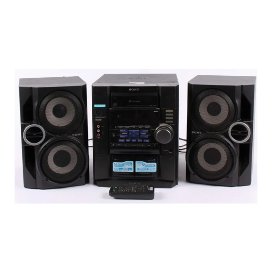
Sony MHC-RG60 Service Manual
Mini hi-fi component system
Hide thumbs
Also See for MHC-RG60:
- Operating instructions manual (32 pages) ,
- Instruction manual (32 pages)
Table of Contents
Advertisement
Quick Links
SERVICE MANUAL
Ver 1.0 2001. 06
• MHC-RG60 is composed of following models.
As for the service manual, it is issued for each component model,
then, please refer to them.
COMPONENT MODEL NAME
COMPACT DISC DECK
RECEIVER SYSTEM
FRONT SPEAKER
SYSTEM
SURROUND
SPEAKER SYSTEM
SPECIFICATIONS
General
Power requirements
230 V AC, 50/60 Hz
Power consumption
175 watts
0.5 watts (at the Power
Saving Mode)
Approx. 280 x
Dimensions (w/h/d)
Mass
Approx. 10.0 kg
Supplied accessories:
AM loop antenna (1)
Remote Commander (1)
Batteries (2)
FM lead antenna (1)
Front speaker pads (8)
Design and specifications are subject to change
without notice.
Sony Corporation
9-873-194-01
2001F0200-1
Home Audio Company
© 2001.6
Sinagawa Tec Service Manual Production Group
HCD-RG60
SS-RG60
SS-RS60
x
325 421 mm
MHC-RG60
PARTS LIST
Part No.
Description
ACCESSORIES & PACKING MATERIALS
********************************
1-476-503-11
COMMANDER, STANDARD (RM-SR210)
1-501-374-11
ANTENNA, LOOP (AM)
1-501-594-11
ANTENNA (FM)
4-210-254-01
CUSHION (FOOT)
4-232-953-01
COVER, BATTERY (FOR RM-SR210)
4-233-605-11
MANUAL, INSTRUCTION (ENGLISH)
4-233-605-41
MANUAL, INSTRUCTION (FRENCH, SPANISH)(AEP)
4-233-605-51
MANUAL, INSTRUCTION
(GERMAN, DUTCH, ITALIAN,SWEDISH,POLISH)(AEP)
4-233-751-11
MANUAL, INSTRUCTION (DANISH, FINNISH)(AEP)
4-233-751-21
MANUAL, INSTRUCTION (PORTUGUESE)(AEP)
4-233-752-11
MANUAL, INSTRUCTION (TURKISH)(AEP)
4-233-752-21
MANUAL, INSTRUCTION (GREEK)(AEP)
4-233-752-31
MANUAL, INSTRUCTION (HUNGARIAN, CZECH)(AEP)
4-233-752-41
MANUAL, INSTRUCTION (SLOVAK)(AEP)
4-234-054-11
MANUAL, INSTRUCTION (SS-RG60)
MINI Hi-Fi COMPONENT SYSTEM
AEP Model
UK Model
Remark
Advertisement
Table of Contents

Related Manuals for Sony MHC-RG60


Summary of Contents for Sony MHC-RG60
- Page 1 SERVICE MANUAL AEP Model UK Model Ver 1.0 2001. 06 • MHC-RG60 is composed of following models. As for the service manual, it is issued for each component model, then, please refer to them. COMPONENT MODEL NAME COMPACT DISC DECK...
- Page 2 6 to 16 ohms SURROUND SPEAKER accepts impedance of 6 to 16 ohms — Continued on next page — MINI HI-FI COMPONENT SYSTEM Sony Corporation 9-873-193-01 2001G0200-1 Home Audio Company © 2001.7 Shinagawa Tec Service Manual Production Group...
- Page 3 Recording system 4-track 2-channel stereo Frequency response 40 – 13,000 Hz (±3 dB), using Sony TYPE I The laser diode in the optical pick-up block may suffer electrostatic cassette break-down because of the potential difference generated by the Tuner section charged electrostatic load, etc.
-
Page 4: Table Of Contents
HCD-RG60 TABLE OF CONTENTS 1. SERVICE NOTE .............. 4 2. GENERAL ................. 5 3. DISASSEMBY ..............7 4. TEST MODE ..............13 5. ELECTRICAL ADJUSTMENTS ......17 6. DIAGRAMS 6-1. Circuit Board Location ............. 19 6-2. Block Diagrams –Tuner Section– ........20 Block Diagrams –Main Section–... -
Page 5: Service Note
HCD-RG60 SECTION 1 SERVICE NOTE REMOVING THE PANEL BOARD AND THE KEY BOARD * The panel board and the key board only are connected to the front panel by means of hot-melting the plastics. 5 Key board 3 Panel board 1 Connector 13p (CN712) 2 Cut the seven melted-connection points... -
Page 6: General
HCD-RG60 SECTION 2 GENERAL This section is extracted from instruction manual. Main unit 1 2 3 4 8 9 q; AUDIO jacks ed MD (VIDEO) qg BUTTON DESCRIPTIONS CD qs MOVIE EQ 9 CD SYNC wf v/V/b/B 5 MUSIC EQ 6 Deck A wl Z (deck A) wk P FILE qa... - Page 7 HCD-RG60 Remote Control 1 2 3 4 CD qj MD (VIDEO) 9 BUTTON DESCRIPTIONS CLEAR 6 P FILE qd CLOCK/TIMER SELECT 2 PRESET EQ qg v/V/b/B qs CLOCK/TIMER SET 3 SLEEP 1 M (fast forward)/TUNING D.SKIP ql SURROUND 0 . (go back)/PRESET EFFECT ON/OFF qa TAPE A/B 8 –...
-
Page 8: Disassemby
HCD-RG60 SECTION 3 DISASSEMBLY Note : Disassemble the unit in the order as shown below. Case (Side-R, Side-L, Top) CD door Front panel section Tape mechanism deck Panel board Key board CD mechanism deck Base unit, BD board (CDM58B) Driver board, Moter board, Address sensor board Sensor board, Sub trans board, Video out board, Back panel, Chassis section Surround board, DC fan, Power transformer (Trans board) - Page 9 HCD-RG60 3-2. CD DDOR CD door CD mechanism deck (CDM58B) 1 Turn the pulley to the direction of arrow. Front panel side pulley 2 Pull-out the disc tray. 3-3. FRONT PANEL SECTION 7 Connector (CN714) CD mechanism deck (CDM58B) 2 Connector (CN701) 1 Wire (flat type) (CN102)
- Page 10 HCD-RG60 3-4. TAPE MECHANISM DECK 1 Six screws (+BVTP 2.6 × 8) 2 Tape mechanism deck 3-5. PANEL BOARD 6 Panel board 4 Connector (CN712) 2 Vol knob ring 5 Cut the seven melted-connection points with a cutting plier. 1 Volume knob Note: When attching the panel board, refer to "Service Note"...
- Page 11 HCD-RG60 3-6. KEY BOARD 2 Key board 1 Cut the six melted-connection points with a cutting plier. Note: When attching the Key board, refer to "Service Note" on page 4. 3-7. SENSOR BOARD, SUB TRANS BOARD, VIDEO OUT BOARD, BACK PANEL, SURROUND BOARD, DC FAN, POWER TRANSFORMER (TRANS BOARD) 5 Connector (CN2) Back panel...
- Page 12 HCD-RG60 3-8. MAIN BOARD, POWER AMP BOARD 7 Heat sink 6 Two screws (+BVTT 3 × 6) 4 Three screws (+BVTT 3 × 6) Main board 5 Power amp board 3 Two screws (+BVTP 3 × 16) 2 Main board 1 Two screws (+BVTT 3 ×...
- Page 13 HCD-RG60 3-10. DRIVER BOARD, MOTOR BOARD AND ADDRESS SENSOR BOARD q; Screw (+PTPWH 2.6 × 8) 4 Two screws (+BVTP 2.6 × 8) 8 Motor board 6 Wire (flat type) 8p (CN721) 5 Remove the two solderings of motor. qs Screw (+BVTP 2.6 × 8) qa Tray 7 Connector 4p (CN722) qd Address sensor board...
-
Page 14: Test Mode
HCD-RG60 SECTION 4 TEST MODE [MC Cold Reset] [Change-over of AM Tuner Step between 9 kHz and • The cold reset clears all data including preset data stored in the 10 kHz] RAM to initial conditions. Execute this mode when returning •... - Page 15 HCD-RG60 [MC Test Mode] [Microprocessor version display] • This mode is used to check operations of the respective sections • If the following operation is performed during the POWER OFF of Amplifier, TUNER, CD and Tape. in the modes other than the POWER SAVE mode (i.e., while the Demo display shows the watch time), Procedure: 1.
- Page 16 HCD-RG60 [Aging Mode] This mode can be used for operation check of CD section and tape deck section. • If an error occurred: The aging operation stops and display status. • If no error occurs: The aging operation continues repeatedly. 1.
- Page 17 HCD-RG60 2) Operation during aging mode In the aging mode, the program is executed in the following sequence. (1) The disc tray opens and closes. (2) The mechanism accesses DISC 2 and makes an attempt to read TOC. However, since there are no discs, a message “CD2 NO DISC”...
-
Page 18: Electrical Adjustments
HCD-RG60 SECTION 5 ELECTRICAL ADJUSTMENTS FM Tuned Level Adjustment CD SECTION FM RF Signalgenerator Note : 1. CD Block is basically designed to operate without adjustment. 75 Ω coaxial Therefore, check each item in order given. 2. Use YEDS-18 disc (3-702-101-01) unless otherwise indicated. 3. - Page 19 HCD-RG60 Note : Clear RF signal waveform means that the shape “ ◊ ” can be clearly Adjustment Location: distinguished at the center of the waveform. [BD BOARD] (Conductor Side) RF signal waveform VOLT/DIV : 200mV TIME/DIV : 500ns level : 1.45 ± 0.3Vp-p E-F Balance (1 Track jump) Check oscilloscope BD board...
-
Page 20: Diagrams
HCD-RG60 SECTION 6 6-1. CIRCUIT BOARD LOCATION DIAGRAMS MOTOR board THIS NOTE IS COMMON FOR PRINTED WIRING BOARDS AND SCHEMATIC DIAGRAMS. (In addition to this, the necessary note is printed in each block.) ADDRESS SENSOR board VIDEO OUT board Note on Schematic Diagram: Note on Printed Wiring Boards: •... -
Page 21: Block Diagrams -Tuner Section
HCD-RG60 6-2. BLOCK DIAGRAMS AM/FM FRONT-END, IFAMP, MPX TUNER SECTION IC101 Q101 CF101 CF102 RF IF L-CH • RCH is omitted FM IF L OUT Q103 • Signal Path MAIN T101 R OUT R-CH SECTION : FM FM DET Q102 : AM A+12V AM IF IN... -
Page 22: Block Diagrams -Main Section
HCD-RG60 MAIN SECTION IC501 JK302 L-CH TUNER TUNER L SECTION OUT L SPEAKER POWER IMPEDANCE Q361,362 Q381,382 USE 6-16Ω R CH LOUT MUTE MUTE CD L OUT R R CH Q301 DETECT SECTION CONT JK501 Q501 Q383 Q386,387 J301 D502 SURROUND OVER LOAD PROTECT... -
Page 23: Printed Wiring Board -Bd Section
HCD-RG60 6-3. PRINTED WIRING BOARD – BD SECTION – • See page 19 for Circuit Boards Location. • Semiconductor Location Ref. No. Location IC101 IC102 IC103 Q101 TP(TE0) (VC) TP(FE0) (RF) TP(FE1) TP(AGC CON) TP(D GND) (XPCK) CN102 (Page 24) -
Page 24: Schematic Diagram -Bd Section
HCD-RG60 6-4. SCHEMATIC DIAGRAM – BD SECTION – • See page 19 for Waveforms. • See page 40,41 for IC Block Diagrams. IC B/D IC B/D IC B/D (5/5) CN102 (Page 29) -
Page 25: Printed Wiring Board -Main Section
HCD-RG60 6-5. PRINTED WIRING BOARD – MAIN SECTION – • See page 19 for Circuit Boards Location. DRIVER BOARD MAIN BOARD BOARD (Page 36) (Page 22) • Semiconductor Location CLP2 JW232 JR633 Ref. No. Location R119 JW004 R116 Ref. No. Location IC102 R114 JW311... -
Page 26: Schematic Diagram -Main Section (1/5)
HCD-RG60 6-6. SCHEMATIC DIAGRAM – MAIN SECTION (1/5) – • See page 42 for IC Block Diagrams. -
Page 27: Schematic Diagram -Main Section (2/5)
HCD-RG60 6-7. SCHEMATIC DIAGRAM – MAIN SECTION (2/5) – • See page 19 for Waveforms. • See page 41,42 for IC Block Diagrams. -
Page 28: Schematic Diagram -Main Section (3/5)
HCD-RG60 6-8. SCHEMATIC DIAGRAM – MAIN SECTION (3/5) –... -
Page 29: Schematic Diagram -Main Section (4/5)
HCD-RG60 6-9. SCHEMATIC DIAGRAM – MAIN SECTION (4/5) – • See page 19 for Waveforms. • See page 37 for IC Pin Function Description. -
Page 30: Schematic Diagram -Main Section (5/5)
HCD-RG60 6-10. SCHEMATIC DIAGRAM – MAIN SECTION (5/5) –... -
Page 31: Printed Wiring Board -Power Amp Section
HCD-RG60 6-11. PRINTED WIRING BOARD – POWER AMP SECTION – • See page 19 for Circuit Boards Location. SENSOR BOARD POWER AMP BOARD (CHASSIS) • Semiconductor Location Ref. No. Location D501 D502 TH501 D541 D542 D543 R519 D551 IC501 MAIN BOARD CN504 CN506 (Page 24) -
Page 32: Schematic Diagram -Power Amp Section
HCD-RG60 6-12. SCHEMATIC DIAGRAM – POWER AMP SECTION –... -
Page 33: Printed Wiring Board -Panel Section
HCD-RG60 6-13. PRINTED WIRING BOARD – PANEL SECTION – • See page 19 for Circuit Boards Location. PANEL BOARD • Semiconductor Location Ref. No. Location D701 D702 TUNER/BAND D703 D704 61 60 IC701 D705 D706 D707 D708 D710 D713 20 21 VIDEO D716 D717... -
Page 34: Schematic Diagram -Panel Section
HCD-RG60 6-14. SCHEMATIC DIAGRAM – PANEL SECTION – • See page 19 for Waveforms. -
Page 35: Printed Wiring Board -Trans Section
HCD-RG60 6-15. PRINTED WIRING BOARD – TRANS SECTION – • See page 19 for Circuit Boards Location. SUB TRANS BOARD • Semiconductor Location AC IN Ref. No. Location D901 D902 D903 D904 D905 D911 D912 D913 IC901 Q901 Q911 1-681-445- (11) TRANS BOARD T911... -
Page 36: Schematic Diagram -Trans Section
HCD-RG60 6-16. SCHEMATIC DIAGRAM – TRANS SECTION –... -
Page 37: Printed Wiring Board -Driver Section
HCD-RG60 6-17. PRINTED WIRING BOARD – DRIVER SECTION – • See page 19 for Circuit Boards Location. • Semiconductor Location C712 Ref. No. Location D707 IC701 IC711 (Page 24) 6-18. SCHEMATIC DIAGRAM – DRIVER SECTION – • See page 42 for IC Block Diagrams. IC B/D C712 (4/5) -
Page 38: Ic Pin Function Description
HCD-RG60 6-19. IC PIN FUNCTION DESCRIPTION • MAIN BOARD IC401 M30622MCA-B23FP (MASTER CONTROL) Pin No. Pin Name Description S-OUT Serial data output the display control. S-CLK Serial clock output from main controller. S-BSY Busy signal input from the display control. “L” : busy REMOTE IN Pemoto commander input. - Page 39 HCD-RG60 Pin No. Pin Name Description NO USE — Not used. CENT-MUTE — Not used. REAR-MUT — Not used. 494-DAT — Not used. 494-CLK — Not used. 494-LT — Not used. SUR1 — Not used. SUR2 — Not used. SUR3 —...
- Page 40 HCD-RG60 • PANEL BOARD IC701 µPD780232GC-031-8BT (DISPLAY CONTROL) Pin No. Pin Name Description Power supply.(+5V) — Connected to ground. System clock output terminal.(5MHz) System clock input terminal.(5MHz) — Connected to ground. RESET Reset signal input from main controller. S-CLK Serial clock input from main controller. S-IN Serial data input from main controller.
-
Page 41: Ic Block Diagrams
HCD-RG60 6-20. IC BLOCK DIAGRAMS IC101 CXD2587Q (BD BOARD) ERROR DIGITAL CORRECTOR DIGITAL ASYMMETRY CORRECTION OPERATIONAL LRCK AMPLIFIER ANALOG SWITCH PCMD INTERFACE DEMODULATOR CONVERTER EMPH XVDD XTAI TIMING LOGIC CLOCK XTAO XTSL GENERATOR XVSS TES1 AVDD1 TEST AOUT1 SERVO DSP PWM GENERATOR AIN1 FRDR... - Page 42 HCD-RG60 IC103 CXA2568M-T6 (BD BOARD) IC103 BU1924 (MAIN BOARD) APC PD AMP LC/PD LD_ON CLOCK HOLD TEST AGCVTH VREF APC LD AMP HOLD_SW AGCCONT DEFFERENTIAL BIPHASE PLL 57KHz (50%/30% DECODER DECODER 1187.5Hz RDS/ARI OFF) RF_BOT 8TH SWITCHED CAPACITOR FILTER RFTC RF SUMMING AMP RF_EQ_AMP RF_1...
- Page 43 HCD-RG60 IC101 BA1450 (MAIN BOARD) AM IF VREG DECODER DRIVER COMP IC701 BA6956AN (DRIVER BOARD) IC201 TA8189N (MAIN BOARD) METAL TAPE A CH2/A CH2/B /TAPE B – – CONTROL LOGIC VREF1 IREF VREF2 – – CH1/A CH1/B METAL GND1...
-
Page 44: Exploded Views
HCD-RG60 SECTION 7 EXPLODED VIEWS NOTE: • -XX, -X mean standardized parts, so they may The components identified by mark 0 or have some differences from the original one. dotted line with mark 0 are critical for safety. • Items marked “*” are not stocked since they Replace only with part number specified. -
Page 45: Front Panel Section
HCD-RG60 7-2. FRONT PANEL SECTION * For service only (Be sure to refer to "Service note" on page 4.) not supplied not supplied FLD1 Ref. No. Part No. Description Remark Ref. No. Part No. Description Remark 4-234-015-01 VOL KNOB RING 1-681-447-11 KEY BOARD 4-234-019-01 VOLUME KNOB A-4726-035-A PANEL BOARD COMPLETE... -
Page 46: Chassis Section
HCD-RG60 7-3. CHASSIS SECTION T911 not supplied not supplied Ref. No. Part No. Description Remark Ref. No. Part No. Description Remark 1-773-049-11 WIRE (FLAT TYPE) (17 CORE) 3-703-244-00 BUSHING (2104), CORD A-4726-743-A MAIN BOARD COMPLETE 1-681-444-21 TRANS BOARD 0 108 * 103 4-988-533-01 HOLDER, PWB 1-769-744-81 CORD, POWER... -
Page 47: Cd Mechanism Deck Section
HCD-RG60 7-4. CD MECHANISM DECK SECTION M721 supplied not supplied supplied Ref. No. Part No. Description Remarks Ref. No. Part No. Description Remarks X-4951-889-1 HOLDER (BU) ASSY 4-933-134-11 SCREW (+PTPWH M2.6X8) 4-222-095-01 BELT 4-221-679-01 CAM (RELAY) 4-227-045-11 SPRING (INSULATOR), COIL 4-231-452-01 TABLE (NEW) 4-221-686-01 LEVER (CHANGE) 4-985-672-01 SCREW (+PTPWH M2.6), FLOATING... -
Page 48: Electrical Parts List
HCD-RG60 SECTION 8 ADDRESS SENSOR ELECTRICAL PARTS LIST Ref. No. Part No. Description Remarks Ref. No. Part No. Description Remarks Note: • SEMICONDUCTORS • Due to standardization, replacements in the parts The components identified by In each case, u: µ , for example: list may be different from the parts specified in the mark 0 or dotted line with mark uA...: µ... - Page 49 HCD-RG60 DRIVER Ref. No. Part No. Description Remarks Ref. No. Part No. Description Remarks R107 1-216-073-00 RES-CHIP 1/10W 1-681-447-11 KEY BOARD ********* R108 1-216-061-00 RES-CHIP 3.3K 1/10W R109 1-216-121-11 RES-CHIP 1/10W R110 1-216-025-11 RES-CHIP 1/10W < DIODE > R111 1-216-121-11 RES-CHIP 1/10W D707 8-719-058-04 DIODE SEL5223S-TP15 (REC PAUSE/START)
- Page 50 HCD-RG60 MAIN Ref. No. Part No. Description Remarks Ref. No. Part No. Description Remarks S716 1-762-875-21 SWITCH, KEYBOARD (gG) C133 1-126-957-11 ELECT 0.22uF S717 1-762-875-21 SWITCH, KEYBOARD (X) C134 1-104-760-11 CERAMIC CHIP 0.047uF S718 1-762-875-21 SWITCH, KEYBOARD (>) S719 1-762-875-21 SWITCH, KEYBOARD (M +) C135 1-126-963-11 ELECT 4.7uF...
- Page 51 HCD-RG60 MAIN Ref. No. Part No. Description Remarks Ref. No. Part No. Description Remarks C236 1-126-933-11 ELECT 100uF C361 1-107-721-11 ELECT 4.7uF 100V C236A 1-162-949-11 CERAMIC CHIP 47PF C362 1-107-721-11 ELECT 4.7uF 100V C237 1-162-962-11 CERAMIC CHIP 470PF C363 1-107-717-11 ELECT 47uF C364 1-109-953-11 ELECT...
- Page 52 HCD-RG60 MAIN Ref. No. Part No. Description Remarks Ref. No. Part No. Description Remarks C692 1-126-935-11 ELECT 470uF D690 8-719-083-89 DIODE 11ES2N-TB5 C693 1-130-483-00 MYLAR 0.01uF D691 8-719-083-89 DIODE 11ES2N-TB5 C694 1-130-483-00 MYLAR 0.01uF C697 1-126-943-11 ELECT 2200uF D692 8-719-083-89 DIODE 11ES2N-TB5 C698 1-126-964-11 ELECT 10uF...
- Page 53 HCD-RG60 MAIN Ref. No. Part No. Description Remarks Ref. No. Part No. Description Remarks JR609 1-216-864-11 METAL CHIP 1/16W Q382 8-729-119-78 TRANSISTOR 2SC2785-HFE JR633 1-216-864-11 METAL CHIP 1/16W Q383 8-729-119-76 TRANSISTOR 2SA1175-HFE JR634 1-216-864-11 METAL CHIP 1/16W JR635 1-216-864-11 METAL CHIP 1/16W Q384 8-729-900-80 TRANSISTOR DTC114ES...
- Page 54 HCD-RG60 MAIN Ref. No. Part No. Description Remarks Ref. No. Part No. Description Remarks R174 1-216-821-11 METAL CHIP 1/16W R258 1-216-813-11 METAL CHIP 1/16W R175 1-216-817-11 METAL CHIP 1/16W R260 1-216-816-11 METAL CHIP 1/16W R177 1-216-809-11 METAL CHIP 1/16W R261 1-216-816-11 METAL CHIP 1/16W R181...
- Page 55 HCD-RG60 MAIN Ref. No. Part No. Description Remarks Ref. No. Part No. Description Remarks R370 1-216-829-11 METAL CHIP 4.7K 1/16W R639 1-216-841-11 METAL CHIP 1/16W R371 1-216-841-11 METAL CHIP 1/16W R640 1-216-839-11 METAL CHIP 1/16W R372 1-216-841-11 METAL CHIP 1/16W R641 1-216-841-11 METAL CHIP 1/16W...
- Page 56 HCD-RG60 MOTOR PANEL Ref. No. Part No. Description Remarks Ref. No. Part No. Description Remarks < CAPACITOR > < DIODE > C721 1-162-306-11 CERAMIC 0.01uF D701 8-719-071-44 DIODE SELS5223C-TP15 (`/1) D702 8-719-084-19 DIODE LTL77HKYTNN (MD (VIDEO)) < CONNECTOR > D703 8-719-084-19 DIODE LTL77HKYTNN (TAPE A/B) D704 8-719-084-19 DIODE LTL77HKYTNN (CD)
- Page 57 HCD-RG60 PANEL POWER AMP Ref. No. Part No. Description Remarks Ref. No. Part No. Description Remarks R757 1-249-429-11 CARBON 1/4W < CONNECTOR > R758 1-247-807-31 CARBON 1/4W R759 1-249-429-11 CARBON 1/4W CN502 1-778-981-21 CONNECTOR, BOARD TO BOARD 13P R760 1-247-807-31 CARBON 1/4W CN503 1-778-981-21 CONNECTOR, BOARD TO BOARD 13P...
- Page 58 HCD-RG60 POWER AMP SENSOR SUB TRANS SURROUND TRANS Ref. No. Part No. Description Remarks Ref. No. Part No. Description Remarks R525 1-249-437-11 CARBON 1/4W < TRANSFORMER > R541 1-260-115-11 CARBON 1/2W R551 1-249-417-11 CARBON 1/4W F 0 T901 1-435-824-21 TRANSFORMER, POWER ****************************************************** R552 1-249-438-11 CARBON...
- Page 59 HCD-RG60 VIDEO OUT Ref. No. Part No. Description Remarks 1-681-441-21 VIDEO OUT BOARD *************** < CONNECTOR > CN714 1-564-505-11 PLUG, CONNECTOR 2P < JACK > J705 1-774-227-11 JACK, PIN 1P (VIDEO OUT) ****************************************************** MISCELLANEOUS ************* 1-796-124-11 DECK, MECH 1-773-049-11 WIRE (FLAT TYPE) (17 CORE) 1-791-897-11 WIRE (FLAT TYPE) (19 CORE) 0 108 1-769-744-81 CORD, POWER...
- Page 60 : Approx.215 × 325 × 223 mm Dimensions(w/h/d) Mass : Approx.4.3 kg net per speaker Design and specifications are subject to change without notice. SPEAKER SYSTEM Sony Corporation 9-873-818-13 2002A1600-1 Home Audio Company © 2002.1 Published by Sony Engineering Corporation...
- Page 61 SS-DX30/RG40/RG60/VX333 Ver 1.2 2002.01 • Abbreviation EXPLODED VIEW AND PARTS LIST CND : Canadian model. R ch Ref. No. Part No. Description Remarks Ref. No. Part No. Description Remarks A-4412-773-A FRONT PANEL (R) ASSY (BLACK)(DX30,VX333) 1-529-936-11 LOUD SPEAKER (13cm)(VX333) A-4412-775-A FRONT PANEL (L) ASSY (BLACK)(DX30,VX333) 1-544-788-11 SPEAKER (13cm)(RG40:AEP,UK/RG60) X-4953-745-1 FRONT PANEL ASSY L (RG40:AEP,UK/RG60) A-2004-979-A SPEAKER CABINET (R) ASSY (SILVER)(VX333)
- Page 62 SS-DX30/RG40/RG60/VX333 MEMO...
- Page 63 SS-DX30/RG40/RG60/VX333 REVISION HISTORY Clicking the version allows you to jump to the revised page. Also, clicking the version at the upper right on the revised page allows you to jump to the next revised page. Ver. Date Description of Revision 2001.02 2001.08 Addition of the color silver in SS-VX333.
- Page 64 Approx.180 × 105 × 200 mm Dimensions (w/h/d) Mass Approx.1.0 kg net per speaker Design and specifications are subject to change without notice. SPEAKER SYSTEM Sony Corporation 9-873-231-01 2001F0500-1 Home Audio Company C 2001.6 Shinagawa Tec Service Manual Production Group...
- Page 65 SS-CT60AV/CT70AV/RC60AV/RC70AV/RS60/RS60AV/RS70AV EXPLODED VIEWS AND PARTS LIST NOTE: • -XX and -X mean standardized parts, so they • Items marked “*” are not stocked since they may have some difference from the original are seldom required for routine service. Some one. delay should be anticipated when ordering •...
- Page 66 SS-CT60AV/CT70AV/RC60AV/RC70AV/RS60/RS60AV/RS70AV (2) SS-RS60/RS60AV/RS70AV not supplied not supplied not supplied Ref. No. Part No. Description Remark Ref. No. Part No. Description Remark 7-685-648-79 SCREW +BVTP 3X12 1-544-927-11 SPEAKER (7cm)
- Page 67 SS-CT60AV/CT70AV/RC60AV/RC70AV/RS60/RS60AV/RS70AV REVISION HISTORY Clicking the version allows you to jump to the revised page. Also, clicking the version at the upper right on the revised page allows you to jump to the next revised page. Ver. Date Description of Revision 2001.06...