Table of Contents
Advertisement
Quick Links
Advertisement
Table of Contents

Related Manuals for Martin Audio WAVEFRONT PRECISION WPC


Summary of Contents for Martin Audio WAVEFRONT PRECISION WPC
- Page 1 Optimised Line Array User Guide 7/18...
-
Page 2: Table Of Contents
WPC System USER GUIDE Contents Introduction: Wavefront Precision ���������������������������������������������������������������������������������������������������������������� 3 About This Manual ��������������������������������������������������������������������������������������������������������������������������������������� 3 Amplification, DSP, and Networking ������������������������������������������������������������������������������������������������������������� 3 Important Safety Instructions ����������������������������������������������������������������������������������������������������������������������� 4 CAUTION ������������������������������������������������������������������������������������������������������������������������������������������������� 4 Unpacking the Units ������������������������������������������������������������������������������������������������������������������������������������� 5 WPC �������������������������������������������������������������������������������������������������������������������������������������������������������������� 6 Mechanical Design ������������������������������������������������������������������������������������������������������������������������������������ 7 Acoustic Design ������������������������������������������������������������������������������������������������������������������������������������������... -
Page 3: Introduction: Wavefront Precision
Drawing on the research and technology behind MLA® Series, the Wavefront Precision Series is a new generation of multi- purpose line arrays designed to bring Martin Audio’s legendary sound, coverage consistency and control to a broader range of touring applications, installations and budgets. -
Page 4: Important Safety Instructions
To reduce the risk of electric shock do not remove any covers. There are no user serviceable parts inside the units. Refer servicing to qualified service personnel only. Call Martin Audio Ltd on +44 (0) 1494 535312 or e-mail info@martin-audio.com for service. -
Page 5: Unpacking The Units
WPC System USER GUIDE Unpacking the Units After unpacking the unit, please check it carefully for any damage. If any is found, immediately notify the carrier concerned – you, the consignee, must instigate any claim. Please retain all packaging in case you need to return the unit. Please think of the environment. -
Page 6: Wpc
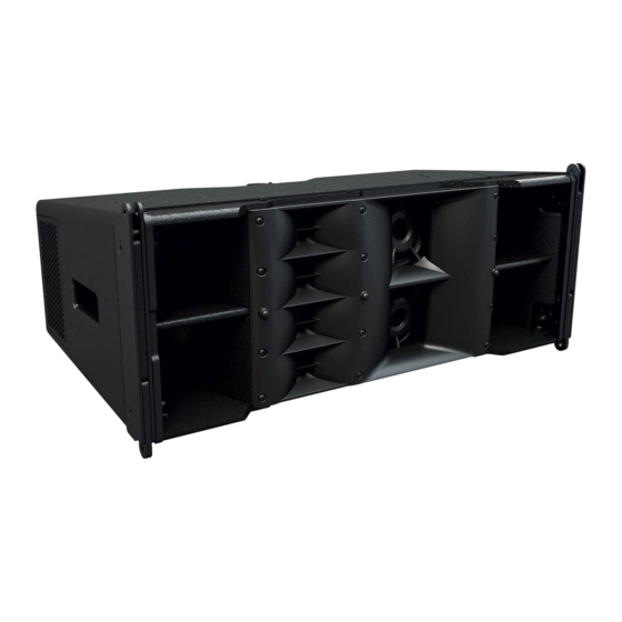
WPC System USER GUIDE WPC is a three-way passive compact line array element consisting of two 10” neodymium magnet low frequency drivers in a Hybrid configuration, two 5” neodymium magnet mid frequency drivers, and four 0.7” neodymium magnet high frequency compression drivers loaded by constant directivity waveguides. -
Page 7: Mechanical Design
WPC System USER GUIDE The WPC is a new breed of medium-format optimised line array which brings innovative acoustic design, ultra-high performance and coverage consistency to a wider range of users, applications and budgets than previously possible. A three-way, bi-amp system, it features horn-loaded low-frequency, mid and HF sections to raise efficiency and increase output. -
Page 8: Accessories
WPC System USER GUIDE Accessories SX118 Subwoofer The SX118 is a compact, high performance subwoofer that extends the low frequency operating range of the WPC system to 47Hz and provides exceptional low frequency output for such a compact enclosure. It features a long excursion 18” (460mm) / 4”... -
Page 9: Sx218 Subwoofer
WPC System USER GUIDE SX218 Subwoofer The SX218 is a compact, high performance subwoofer that extends the low frequency operating range of the WPC system to 35Hz and provides exceptional low frequency output for such a compact enclosure. It features two long excursion 18” (460mm) / 4”... -
Page 10: Ik42 Amplifier
Ethernet is used for system remote control and monitoring via Martin Audio’s Vu-Net software application, while a user-friendly front panel interface allows full local control of all features. Dante digital audio network inputs are also provided for digital audio distribution and control. -
Page 11: Display 2.3 Overview
WPC System USER GUIDE DISPLAY 2.3 Overview DISPLAY 2.3 is a unique software application for Wavefront Precision systems which calculates both inter-cabinet splay angles and the DSP parameters for optimum system performance in any given space. Unlike competitors systems which generally use a basic geometric calculation to aim their arrays, DISPLAY uses a completely revolutionary approach using an extremely accurate computer model of the array to analyse the system performance in a drawing of the venue to precisely calculate the parameters for the system to get exactly the coverage you have specified. - Page 12 WPC System USER GUIDE The dashboard changes to show the tabs from left and right in the order in which the design will be completed. First a 2D slice of the venue is created, the Coverage within the venue is specified, the splay angles calculated. A rigging report allows you to deploy the array and whilst that is being done the EQ coefficients are calculated.
- Page 13 WPC System USER GUIDE The coverage tab shows your 2D model with the planes refined into three types;-audience in green, non-audience in red and hard avoid in blue. Each dot represents a virtual microphone position at which the software will take response measurements using the integral computer model.
- Page 14 WPC System USER GUIDE In the splay tab you can refine the quantity and position of the array before the system optimises the inter-cabinet splay angles and the “aim” angle for the flying grid. Once this is complete you can further refine how the array is to be deployed in the Rig tab; choosing for example between a 2 point hang and a single point for which the application will display the best position on the flying frame to give the nearest angle to the optimised aim.
- Page 15 WPC System USER GUIDE With the physical deployment underway you can progress to optimise the EQ. Again you can enter the environmental conditions and can balance the three goals of response in your audience region, leakage to non-audience and the hard avoid performance. By default each are given equal importance but if your application demands particular emphasis on any one of these parameters they can be given greater importance.
- Page 16 Wavefront Precision systems. DISPLAY 2.3 can be downloaded from the Martin audio website here:- https://martin-audio.com/support/software. There is also a comprehensive User Guide to take you through the design process in detail. We strongly recommend downloading the User Guide to fully understand the application.
-
Page 17: Vu-Net 2.1 Overview
Vu-Net 2.1 Overview Vu-Net is Martin Audio’s application which is used to connect to iKon amplifiers and a growing number of products including the MLA family, CDD-Live, PSX and DD12. This makes it possible to create a system with products from several different ranges and control and monitor them from a single software platform. - Page 18 WPC System USER GUIDE The application opens with a blank System diagram. It is possible to add products manually using the Palette on the left but this has limited use, in practical applications, the Discover Devices button is used. The application searches the network for all Vu-Net enabled devices and will run an installation wizard to add them to the Vu- Net project.
- Page 19 WPC System USER GUIDE From here the system allows you up upload the D2P file of your system design. WPC User Guide v1.0 Page 19...
- Page 20 WPC System USER GUIDE You can now return to the project system diagram, double click on the amplifiers and edit the system to suit your application, perhaps adding some delay to align subwoofers. Input EQ can be adjusted to suit your preferences and to compensate for any difficult acoustics. WPC User Guide v1.0 Page 20...
- Page 21 WPC System USER GUIDE The output EQ is greyed out as it is used to apply the EQ created by your DISPLAY project, however the high pass filter is available for adjustment so you can determine the crossover point between the WPC array and your subwoofers. Comprehensive ganging is available so you can ensure that stereo arrays remain completely identical.
- Page 22 Vu-Net is a free download from the Software page of the Martin Audio website here; https://martin-audio.com/support/software It is a comprehensive application with a host of functions to enable control and monitoring of almost every parameter of a system.
- Page 23 WPC System USER GUIDE Rigging WPC WPC User Guide v1.0 Page 23...
- Page 24 WPC System USER GUIDE WPC’s three-point rigging system consists of two rigging points at the front and a single rigging point at the rear of the cabinet. The rear rigging bracket assembly provides six rigging holes allowing for inter-cabinet angles of 0.5°, 1°, 2°, 4°, 6.5° and 10°, as well as STORE, LOCK, and LINK positions, for flying arrays or for use when assembling ground stacked arrays.
- Page 25 WPC System USER GUIDE WPC Connections The WPC has two parallel-wired Neutrik® NL4 connectors on an angled panel at the rear of the cabinet, recessed to avoid damage. Connect speaker cables here, taking care to observe the colour coding of the connectors. The two NL4s are wired in parallel so either can be used as a nominal ‘input’...
-
Page 26: Wpcgridt Touring Flying Frame
WPC System USER GUIDE WPCGRIDt Touring Flying Frame The Touring Flying Frame is a comprehensively featured Flying Frame designed to meet BGVC1 and DIN18800 standards, and capable of lifting up to a maximum of 16 WPC cabinets using either one or two lift points, allowing both positive (up-tilt) and negative (down-tilt) array tilt angles. -
Page 27: Wpcgridi Install Flying Frame
It is designed to meet BGVC1 and DIN18800 standards, and will lift a maximum of 16 WPC cabinets using either two lift points or a single lift point, in which case the lift point position is determined by the Martin Audio DISPLAY software. -
Page 28: Transport Dolly For Four Wpc
WPC System USER GUIDE Transport Dolly for four WPC An optional, dedicated Transport Dolly is available to house an array of four WPC cabinets. This will allow safe transportation and convenient rigging and de-rigging if your system is to be portable Ground Stack Bar This precision alignment bar is used in conjunction with the Touring Flying Frame to define the angle between the WPC array and the Flying Frame when the system is configured for ground stacking. -
Page 29: Inclinometer Assembly
Inclinometer Assembly Martin Audio supplies an optional remote angle monitoring system which can used to reliably check the angle at which the WPC array is flown at (relative to the horizontal). It consists of a sensor (mounted within the Flying Frame) and a remote display unit. -
Page 30: Fitting The Inclinometer Sensor To The Flying Grid
WPC System USER GUIDE Fitting the inclinometer sensor to the Flying Grid The WPC touring flying grid may be fitted with an inclinometer sensor which is available as an optional accessory part number ASM20017. Once coupled with the ASM20019 inclinometer read-out display via a standard 3-pin XLR mic cable, precise measurements of the angle of the array can be taken to ensure that the DISPLAY optimisation is as accurate as possible. -
Page 31: Attach The Box To The Grid
WPC System USER GUIDE Attach the box to the Grid Position the box on the outside of the bracket on the left side of the grid. There are two M4x20mm Cap head screws supplied with the sensor. These go through the holes in the bottom left and top right of the box into the threaded holes in the grid bracket. Tighten using an M3 Allen Key to ensure a tight fit. -
Page 32: The Sensor In Position
PP3 batteries). It can be connected to the read-out sensor with a standard 3-pin XLR mic cable of any length. Martin Audio supply a cable designed specifically for use with the inclinometer system. Part Number PWA00057. This is a 35m cable using high grade AES spec microphone cable fitted with male and female Neutrik NC3XX-HD connectors which are extra rugged and have an IP rating of IP67 to enable use outdoors in all weather conditions. -
Page 33: Flown Systems
WPC System USER GUIDE Flown Systems WPC’s rigging has been derived from the highly successful rigging system employed on the MLA Mini Multicellular system. This has proved to be popular, quick and above all safe. Rigging WPC will be instantly familiar to anyone who has rigged Martin Audio systems in the past, we have made a few minor improvements to make it even easier to use and it has proved to be incredibly quick to fly and land. -
Page 34: Rigging Wpc With The Wpcgridt Touring Flying Frame
IMPORTANT SAFETY NOTE The top of the Transport Dolly has the Martin Audio logo milled into it and arrows to indicate that it must only be pushed in the long direction. The Transport Dolly must not be travelled side-on! WPC User Guide v1.0... - Page 35 WPC System USER GUIDE The following example illustrates the procedure for rigging an array of eight WPC cabinets with the WPCGRIDt Touring Flying Frame: ” Wheel a WPC Transport Dolly complete with four cabinets into place and position it under the chosen rigging point. Fig 6 - transport dolly Fig.
- Page 36 WPC System USER GUIDE WPC User Guide v1.0 Page 36...
- Page 37 WPC System USER GUIDE ” Unlatch the supporting poles from the Transport Dolly tray and lift them off. Fig. 10 - unlatch poles Fig. 11 - remove poles ” With the supporting poles removed from the Transport Dolly the inter-cabinet angles should now be checked or, if not already preselected, set them now according to the predictions from your DISPLAY 2.3 project.
- Page 38 WPC System USER GUIDE ” Attach the WPCGRIDt Flying Frame to the top cabinet. Insert a rigging pin at the front rigging position on each side of the top cabinet. ” Attach the drop link from the rear of the top cabinet to the Flying Frame at the LINK position. WPC User Guide v1.0 Page 38...
- Page 39 WPC System USER GUIDE ” Insert a Rigging Pin at the LOCK position. ” Lift the array clear of the Transport Dolly to a convenient working height. As the array goes up the cabinets will open up to the angles that you have preselected from the DISPLAY 2.3 project prediction. Insert a further Rigging Pin at the LOCK position on each cabinet to lock the inter-cabinet angles.
- Page 40 WPC System USER GUIDE ” Position a second loaded WPC Transport Dolly underneath the array, remove the top and poles, and prepare the cabinets to be added to the array. Fig. 14 - lift array Fig. 15 - position second block ”...
- Page 41 WPC System USER GUIDE ” Unlatch the supporting poles from the Transport Dolly tray and lift them off. Fig. 18 - remove poles Fig. 19 - remove poles ” Preselect the inter-cabinet angles on the lower three cabinets according to the predictions from your DISPLAY 2.3 project. WPC User Guide v1.0 Page 41...
- Page 42 WPC System USER GUIDE ” Lower the array and engage the front rigging points of the fourth cabinet with the front rigging points of the fifth cabinet. Insert a Rigging Pin on both sides. Fig. 20 - lower array Fig. 21 - attach second block ”...
- Page 43 WPC System USER GUIDE ” Swing the bottom four cabinets (which will now be a rigid array due to the locking pins) backwards until butted against the upper half of the array. Insert a pin in the rear rigging bracket at the correct angle. Allow the bottom four cabinets to swing back down and insert a Rigging Pin at the LOCK position on the fourth cabinet.
- Page 44 WPC System USER GUIDE ” Raise the array to the final trim height. The use of either one or two motors allows both negative (down-tilt) or positive (up- tilt) array angles to be easily achieved. Fig. 26 - negative array tilt Fig.
- Page 45 WPC System USER GUIDE ” Stow the supporting poles in the tray of the Transport Dolly and replace the top. Fig. 28 - stow poles Fig. 29 - replace top WPC User Guide v1.0 Page 45...
- Page 46 WPC System USER GUIDE Landing the Array Landing an array is simply a reversal of the rigging procedure outlined above, lowering the array and guiding the bottom four cabinets into a WPC Transport Dolly, unpinning the lower block of four, and repeating with the top four cabinets. ”...
- Page 47 WPC System USER GUIDE ” Unpin the fifth cabinet from the fourth cabinet at the rear, first removing the LOCK pin and then removing the LINK pin. Fig. 32 - remove LOCK pin Fig. 33 - remove LINK pin ” Remove the Rigging Pins from the front of the fifth cabinet at each side. The top four cabinets can now be lifted clear of the Transport Dolly.
-
Page 48: Rigging Wpc With The Wpcgridi Install Flying Frame
WPC System USER GUIDE Rigging WPC with the WPCGRIDi Install Flying Frame WPC cabinets are normally flown one at a time to form an array in a permanent installation, joining cabinets first at the front rigging points and then at the rear, selecting each inter-cabinet angle according to your DISPLAY 2.3 project prediction. An array of up to a maximum of eight WPC cabinets can be flown in this way. - Page 49 WPC System USER GUIDE ” Raise the array and position a second cabinet underneath the first. Attach the front rigging points, inserting a Rigging Pin at each side. Fig. 40 - attach second cabinet Fig. 41 - secure second cabinet ”...
- Page 50 WPC System USER GUIDE ” Continue adding cabinets to the array up to a maximum of eight cabinets, ensuring that the inter-cabinet angles are set correctly according to the DISPLAY 2.3 project prediction. Connect speaker cables to the cabinets as each one is added to the array.
- Page 51 WPC System USER GUIDE ” The use of either one or two motors allows both negative (down-tilt) or positive (up-tilt) array angles to be easily achieved. Fig. 46 - negative array tilt Fig. 47 - positive array tilt WPC User Guide v1.0 Page 51...
- Page 52 WPC System USER GUIDE Ground Stacking WPC - Upward Tilt Ground stacks of WPC cabinets are assembled using the Touring Flying Frame. The front stabiliser bars provide a wide and stable platform for assembling an array of up to six WPC cabinets. Ground stacks can be assembled with either a positive or negative array inclination relative to the ground simply by alternate positioning of the Ground Stack Bar.
- Page 53 WPC System USER GUIDE WPC User Guide v1.0 Page 53...
- Page 54 WPC System USER GUIDE ” Continue to add further cabinets one at a time to the ground stack, securing the front rigging points with Rigging Pins and setting the inter-cabinet angles as you go along, until the ground stack is complete. Fig.
- Page 55 WPC System USER GUIDE Ground Stacking WPC - Downward Tilt This ground stack example is shown with negative (down-tilt) array inclination. ” Place the Touring Flying Frame at the desired location. Position the first cabinet on top of the bar, aligning the lower front rigging points with the rigging points on the bar.
- Page 56 WPC System USER GUIDE ” Continue to add further cabinets one at a time to the ground stack, securing the front rigging points with Rigging Pins and setting the inter-cabinet angles as you go along, until the ground stack is complete. Fig.
-
Page 57: Essential Maintenance
WPC System USER GUIDE Essential Maintenance WPC - Removing the HF/MF Driver Assembly ” To access the HF and MF drive units first unscrew the ten M5 x 20mm countersunk screws securing the loudspeaker grille. ” Remove the grille and set it aside. WPC User Guide v1.0 Page 57... - Page 58 ” Next remove the eight M5 x 20mm screws and two M5 x 45mm screws holding the HF/MF horn assembly in place. ” Now remove the complete HF/MF horn assembly from the cabinet. The HF and MF drivers are serviced only as a complete assembly. Please refer to Martin Audio service departments for replacement or servicing. WPC User Guide v1.0...
-
Page 59: Wpc - Removing A Lf Driver
WPC System USER GUIDE WPC - Removing a LF Driver ” Once the HF/MF horn assembly is removed the LF drive units can be accessed from inside the cabinet, and are secured using screws through the rear of the chassis. Remove the four M6 x 30 cap head screws, flat washers, and spring washers securing the LF drive unit. -
Page 60: Sx118 Subwoofer - Replacing The Drive Unit
WPC System USER GUIDE SX118 Subwoofer - Replacing the Drive Unit ” The front grille locates into slots on the top and bottom of the cabinet. Remove it by inserting a flat blade screwdriver into slots in the grille edge and carefully levering it out of the slot. ”... - Page 61 WPC System USER GUIDE ” Unscrew the eight M6 x 30mm bolts securing the drive unit. Carefully lift the drive unit out of the cabinet and disconnect the speaker cables, making note of the polarity for later reconnection. WPC User Guide v1.0 Page 61...
-
Page 62: Sx218 - Replacing A Drive Unit
WPC System USER GUIDE SX218 - Replacing a Drive Unit ” The front grille locates into slots on the top and bottom of the cabinet. Remove it by inserting a flat blade screwdriver into slots in the grille edge and carefully levering it out of the slot. ”... - Page 63 WPC System USER GUIDE ” Next unscrew the brace retaining screws and remove the grille braces. ” Unscrew the eight M6 x 30mm bolts securing the drive unit. WPC User Guide v1.0 Page 63...
- Page 64 WPC System USER GUIDE ” Carefully lift the drive unit out of the cabinet and disconnect the speaker cables, making note of the polarity for later reconnection. WPC User Guide v1.0 Page 64...
- Page 65 WPC System USER GUIDE Specifications: WPC TYPE Three-way, bi-amp line array element FREQUENCY RESPONSE 65Hz - 18kHz ±3dB MAXIMUM SPL @1M 135dB DRIVERS 2 x 10” (250mm) / 2.5” (63mm) voice coil, long excursion, vented pole, neodymium magnet drivers, Hybrid slot-horn loaded 2 x 5”...
- Page 66 WPC System USER GUIDE Specifications: SX118 TYPE Single-driver, direct radiating subwoofer FREQUENCY RESPONSE 47Hz - 150Hz ±3dB, -10dB @ 41Hz SENSITIVITY 102dB DRIVER 18” (460mm)/4” (100mm) voice coil, long excursion, ferrite magnet, waterproof cone RATED POWER 1000W AES, 4000W peak MAXIMUM SPL @1M 138dB SYSTEM AMPLIFIER...
- Page 67 WPC System USER GUIDE Specifications: SX218 TYPE Dual-driver, direct radiating subwoofer FREQUENCY RESPONSE 35Hz - 150Hz ±3dB, -10dB @ 30Hz SENSITIVITY 105dB DRIVERS 2 x 18” (460mm) / 4” (100mm) voice coil, long excursion MAXIMUM SPL @1M 144dB DRIVERS 2 x 18” (460mm) / 4” (100mm) voice coil, long excursion SYSTEM AMPLIFIER iKON iK42, iK81 NOMINAL IMPEDANCE...
- Page 68 All information is Copyright © 2017 Martin Audio Ltd. Martin Audio, the Martin Audio logo and Hybrid are registered trademarks of Martin Audio Ltd. in the United Kingdom, United States and other countries; all other Martin Audio trademarks are the property of Martin Audio Ltd.