Table of Contents
Advertisement
Quick Links
Advertisement
Table of Contents

Related Manuals for Martin Audio WPM


Summary of Contents for Martin Audio WPM
- Page 1 Optimised Line Array User Guide...
-
Page 2: Table Of Contents
Landing the Array ��������������������������������������������������������������������������������������������������������������������������������� 37 Rigging WPM with the WPMGRIDi Install Flying Frame ����������������������������������������������������������������������� 38 Rigging WPM with the WPMGRIDi Install Flying Frame - Single Box Method �������������������������������������� 40 Pole Mounting WPM with the Pole Mount and Universal Bracket ������������������������������������������������������� 45 WPM User Guide v1.0... - Page 3 WPM System USER GUIDE Flown WPM Array using the Universal Tilt Bracket ������������������������������������������������������������������������������ 50 Fully Flown WPM Arrays ����������������������������������������������������������������������������������������������������������������������� 52 Essential Maintenance ������������������������������������������������������������������������������������������������������������������������������� 57 WPM - Replacing a LF Drive Unit ������������������������������������������������������������������������������������������������������������� 57 WPM - Replacing the HF Drive Units ������������������������������������������������������������������������������������������������������� 60 MSX Passive Subwoofer - Replacing the Drive Unit ���������������������������������������������������������������������������������...
-
Page 4: Introduction: Wavefront Precision
About This Manual This manual explains in detail the individual components that comprise a complete WPM system. System wiring and rigging is explained and the two key software packages are covered. It is not however the intention for this manual to be the sole tutorial medium for those wishing to use the system. -
Page 5: Important Safety Instructions
To reduce the risk of electric shock do not remove any covers. There are no user serviceable parts inside the units. Refer servicing to qualified service personnel only. Call Martin Audio Ltd on +44 (0) 1494 535312 or e-mail info@martin-audio.com for service. -
Page 6: Unpacking The Units
Please retain all packaging in case you need to return the unit. Please think of the environment. When the product has reached the end of its useful life, please dispose of it responsibly through a recycling centre. WPM User Guide v1.0 Page 6... -
Page 7: Wpm
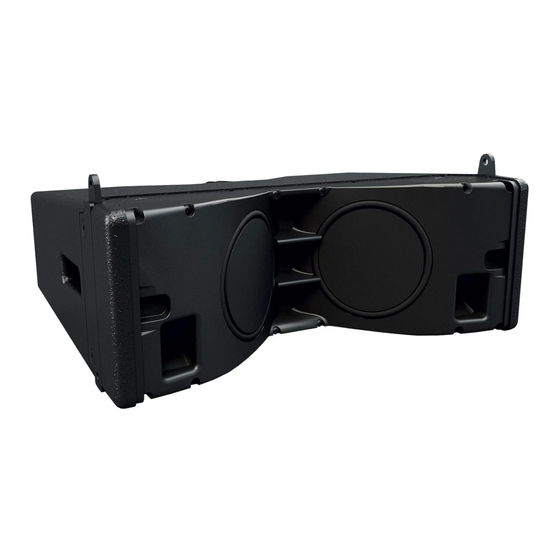
WPM System USER GUIDE WPM is a two-way passive ultra-compact line array element consisting of two 6.5” reflex loaded neodymium magnet low frequency drive units, and three 1.4” neodymium magnet high frequency compression drivers loaded by constant directivity waveguides. In conjunction with automated DISPLAY system design and VU-Net network control software applications, WPM features scalable resolution for advanced array control, resulting in outstanding levels of consistent, high quality audio that can be distributed to every point throughout the audience in a venue. -
Page 8: Mechanical Design
Acoustic Design The acoustic design of WPM is uniquely innovative. The LF drivers are located in the side walls of the HF horn – an arrangement which would introduce acoustic cavities which would degrade the horizontal dispersion if conventional cone drivers were used. -
Page 9: Accessories
WPM system to 50Hz and provides exceptional low frequency output for such a compact enclosure. It features a long excursion 15” (380mm) / 4” (100mm) voice coil driver in a compact reflex enclosure. It is the same width as the WPM cabinet and therefore can be integrated into flown arrays or pole mount systems with WPM. -
Page 10: Sx118 Subwoofer
SX118 Subwoofer The SX118 is a compact, high performance subwoofer that extends the low frequency operating range of the WPM system to 47Hz and provides exceptional low frequency output for such a compact enclosure. It features a long excursion 18” (460mm) / 4”... -
Page 11: Sx218 Subwoofer
SX218 Subwoofer The SX218 is a compact, high performance subwoofer that extends the low frequency operating range of the WPM system to 35Hz and provides exceptional low frequency output for such a compact enclosure. It features two long excursion 18” (460mm) / 4”... -
Page 12: Ik81 Amplifier
Powerful DSP is fully integrated into the iK81 to provide a multitude of features. It also provides up to 1000 FIR filter taps @ 48kHz on each output channel, which is essential to implement DISPLAY’s wide bandwidth optimisation process in the WPM line array. -
Page 13: Display 2.3 Overview
DISPLAY opens with a Dashboard at the top of the screen the initial view prompting you to specify your array which is the first step of the design process. WPM or WPC are available along with the Multicellular family of products. You next specify how your array will be deployed, flown, ground stacked or pole mounted (WPM only), specify the number of cabinets and give the array a name. - Page 14 The array is positioned and the audience region specified from start to finish. WPM User Guide v1.0 Page 14...
- Page 15 In the splay tab you can refine the quantity and position of the array before the system optimises the inter-cabinet splay angles and the “aim” angle for the flying grid. WPM User Guide v1.0 Page 15...
- Page 16 EQ is optimised for the actual physical position in which the array is installed. Finally the load on each flying point is shown and critically the Rig tab shows if the array is safe and meets both BGVC1 and DIN18800 standards. WPM User Guide v1.0 Page 16...
- Page 17 By default each are given equal importance but if your application demands particular emphasis on any one of these parameters they can be given greater importance. The Resolution is entered either 1 to 4 box for WPM or 1 to 3 box for WPC. WPM User Guide v1.0...
- Page 18 Wavefront Precision systems. DISPLAY 2.3 can be downloaded from the Martin audio website here:- https://martin-audio.com/support/software. There is also a comprehensive User Guide to take you through the design process in detail. We strongly recommend downloading the User Guide to fully understand the application.
-
Page 19: Vu-Net 2.1 Overview
Vu-Net 2.1 Overview Vu-Net is Martin Audio’s application which is used to connect to iKon amplifiers and a growing number of products including the MLA family, CDD-Live, PSX and DD12. This makes it possible to create a system with products from several different ranges and control and monitor them from a single software platform. - Page 20 The application searches the network for all Vu-Net enabled devices and will run an installation wizard to add them to the Vu- Net project. The next stage is to right click on the amplifiers to access the Preset Manager. WPM User Guide v1.0 Page 20...
- Page 21 From here the system allows you up upload the D2P file of your system design. You can now return to the project system diagram, double click on the amplifiers and edit the system to suit your application, perhaps adding some delay to align subwoofers. WPM User Guide v1.0 Page 21...
- Page 22 The output EQ is greyed out as it is used to apply the EQ created by your DISPLAY project, however the high pass filter is available for adjustment so you can determine the crossover point between the WPM array and your subwoofers.
- Page 23 Vu-Net is a free download from the Software page of the Martin Audio website here; https://martin-audio.com/support/software It is a comprehensive application with a host of functions to enable control and monitoring of almost every parameter of a system.
- Page 24 USER GUIDE Rigging WPM WPM’s three-point rigging system consists of two rigging points at the front and a single rigging point at the rear of the cabinet. The rear sliding drop down link is equipped with a single point at the top for attaching to cabinets above it, five rigging holes labeled for 0.5°,...
- Page 25 USER GUIDE WPM Connections The WPM has two parallel-wired Neutrik® NL4 connectors on angled panels at the rear of the cabinet, recessed to avoid damage. Connect speaker cables here, taking care to observe the colour coding of the connectors. The two NL4s are wired in parallel so either can be used as a nominal ‘input’ or ‘link’ output. When the system is configured for a single box resolution system each cabinet is connected to a single amplifier channel.
-
Page 26: Wpmgridt Touring Flying Frame
The Touring Flying Frame is a comprehensively featured flybar designed to meet BGVC1 and DIN18800 standards, and capable of lifting up to a maximum of 16 WPM cabinets using either one or two lift points, allowing both positive (up-tilt) and negative (down-tilt) array tilt angles. -
Page 27: Wpmgridi Install Flying Frame
The Install Flying Frame provides a cost effective rigging solution and simplicity of operation for permanently flown installations. It is designed to meet BGVC1 and DIN18800 standards, and will lift a maximum of 16 WPM cabinets using either two lift points or a single lift point, in which case the lift point position is determined by the Martin Audio DISPLAY software. - Page 28 MLA Mini Flying Frame The MLA Mini Flying Frame is used as the main Flying Frame for flown MSX Passive subwoofers, or flown arrays of WPM cabinets and MSX Passive subwoofers, and it can be used with either one or two chain hoists. It provides a four-point rigging system for MSX Passive subwoofers and will support a total of eight cabinets.
- Page 29 The Transition Frame is designed to interface between MSX Passive subwoofers and WPM cabinets in a single combined array. It provides a four point rigging system for MSX Passive subwoofers above the frame, and a three point rigging system for WPM cabinets below the frame.
-
Page 30: Outrigger
Outrigger The Outrigger provides a stable ground support for MSX Passive subwoofers, and pole mount arrays made up of WPM cabinets and MSX Passive subwoofers. Four subwoofer attachment points are provided on each side of the frame, allowing for the ground stack’s centre of gravity to be correctly positioned in relation to the frame. -
Page 31: Inclinometer Assembly
Inclinometer Assembly Martin Audio supplies an optional remote angle monitoring system which can used to reliably check the angle at which the WPM array is flown at (relative to the horizontal). It consists of a sensor (mounted within the Flying Frame) and a remote display unit. -
Page 32: Variable Height Pole
Variable Height Pole This is used to elevate an array of four WPM cabinets above the MSX Passive, SX118, or SX218 as a single assembly. The height of the array can be set to that required according to the DISPLAY project by turning the handle, and then locked in position with the integral clamp. -
Page 33: Wpm Universal Bracket
The Universal Bracket enables an array of up to four WPM cabinets to be pole-mounted on an MSX Passive, SX118, or SX218 subwoofer using the Variable Height Pole at a range of tilt angles from 0° to -18°, or an array of up to four WPM cabinets to be flown from a truss-mounted scaffold clamp. -
Page 34: Flown Systems
WPM’s rigging has been derived from the highly successful rigging system employed on the MLA Mini Multicellular system. This has proved to be popular, quick and above all safe. Rigging WPM will be instantly familiar to anyone who has rigged Martin Audio systems in the past, we have made a few minor improvements to make it even easier to use and it has proved to be incredibly quick to fly and land. -
Page 35: Rigging Wpm With The Wpmgridt Touring Flying Frame
Rigging WPM with the WPMGRIDt Touring Flying Frame The fastest and most efficient procedure for rigging an array of WPM cabinets in a touring environment is to work in blocks of four modules lifting them straight out of the transport case, which is designed to offer excellent protection, ease of handling, and simplified rigging. - Page 36 Fig.11 - attach second block ” Lift the array, align the front rigging positions on the fifth cabinet and secure with Rigging Pins at each side. Fig.12 - insert rigging pin Fig.13 - insert rigging pin WPM User Guide v1.0 Page 36...
-
Page 37: Landing The Array
” Release the drop link from the fourth cabinet and stow it for transportation. ” Lower the array, take the weight of the remaining four cabinets, and release the Rigging Pins from the Flying Frame. ” Lower the cabinets face down on to a transport case. WPM User Guide v1.0 Page 37... -
Page 38: Rigging Wpm With The Wpmgridi Install Flying Frame
Rigging WPM with the WPMGRIDi Install Flying Frame The procedure for flying a permanently installed system of WPM cabinets is practically identical to that for touring applications; the only difference being that this method uses the simplified install Flying Frame with either one or two pickup points. It is recommended that the cabinets are prepared and assembled face down in blocks of four with angles preselected according to the Martin Audio DISPLAY software. - Page 39 WPM System USER GUIDE Fig.18 - insert rigging pin Fig.19 - insert rigging pin WPM User Guide v1.0 Page 39...
-
Page 40: Rigging Wpm With The Wpmgridi Install Flying Frame - Single Box Method
Rigging WPM with the WPMGRIDi Install Flying Frame - Single Box Method WPM cabinets can also be flown one at a time to form an array in a permanent installation. In this case the cabinets are prepared, and inter-cabinet angles preselected, individually according to the Martin Audio DISPLAY software prediction. - Page 41 Fig.23 - secure third cabinet ” Continue to attach the remaining cabinets, ensuring that the inter-cabinet angles are set correctly according to the DISPLAY software. ” Raise the array to the final trim height. WPM User Guide v1.0 Page 41...
- Page 42 USER GUIDE Ground Stacking WPM Ground stacks of WPM cabinets are assembled using the touring Flying Frame. The front stabiliser bars provide a wide and stable platform for assembling an array of up to six WPM cabinets. ” Place the ground stack bar at the desired location. Position the first cabinet on top of the bar, aligning the lower front rigging points with the rigging points on the bar.
- Page 43 Rigging Pins and setting the inter-cabinet angles as you go along, until the ground stack is complete. Fig.28 - attach second cabinet Fig.29 - attach third cabinet Fig.30 - attach fourth cabinet Fig.31 - attach fifth cabinet WPM User Guide v1.0 Page 43...
- Page 44 WPM System USER GUIDE Fig.32 - attach sixth cabinet Fig.33 - complete ground stack WPM User Guide v1.0 Page 44...
-
Page 45: Pole Mounting Wpm With The Pole Mount And Universal Bracket
WPM System USER GUIDE Pole Mounting WPM with the Pole Mount and Universal Bracket ” Start with the MSX Passive subwoofer face down on its wheelboard. Rotate the four dropdown brackets located in the base of the MSX Passive so they are protruding outwards. - Page 46 ” Attach the universal tilt bracket to the top of the telescopic pole and secure by tightening the boss onto the pole using the knob. Fig.40 - attach Universal Bracket Fig.41 - attach Universal Bracket WPM User Guide v1.0 Page 46...
- Page 47 USER GUIDE ” Lift the first WPM cabinet onto the universal tilt bracket. The lugs on the ends of the main cross-arm should mate with the slots in the front corners of the cabinet. Secure these points with flying pins.
- Page 48 Fig.46 - insert rigging pin Fig.47 - insert rigging pin ” Repeat the previous steps twice to add the two remaining WPM cabinets, while referring to the angles which have been defined by the DISPLAY software. Take care to set the correct angles.
- Page 49 ” Depress the safety catch to unlock the height adjustment, and turn the handle to raise the telescopic pole mount so that the vertical distance between the front lower edge of the bottom WPM and the level that the MSX Passive is standing on is at the height defined by the DISPLAY software.
-
Page 50: Flown Wpm Array Using The Universal Tilt Bracket
Pins at the front and rear, with the rear pins in the 0.5° position so that the four cabinets form a ‘flat’ array. Attach the Universal Tilt Bracket to the top of the first WPM. The lugs on the ends of the main cross-arm should mate with the slots in the front corners of the cabinet. - Page 51 DISPLAY software prediction. ” The correct height for the array will be defined by the DISPLAY software prediction, measured from the stage or other floor to the bottom of the lowest cabinet. WPM User Guide v1.0 Page 51...
-
Page 52: Fully Flown Wpm Arrays
Fully Flown WPM Arrays WPM cabinets can be combined with MSX Passive subwoofers to form full-range flown arrays in two possible configurations: twelve WPM cabinets plus three MSX Passive subwoofers, or a subwoofer-only configuration of up to eight MSX Passive. - Page 53 Transition frame. Secure with four Rigging Pins. Fig.62 - attach transition frame Fig.63 - secure transition frame WPM User Guide v1.0 Page 53...
- Page 54 Fig.65 - preselect angles ” Attach the Transition Frame to the upper WPM cabinet. Connect the frame at the rear, where the swinging arm can mate with the upper section of the cabinet rear bracket in three positions to produce an angle between the Transition Frame and the WPM of 0°, 2.5°...
- Page 55 (refer to the DISPLAY data) at the rear fixing with Rigging Pins as before. ” Continue raising the array on the hoist until the lower edge of the bottom WPM cabinet is at the height defined by the DISPLAY software. If the Flying Frame tilt angle is fitted with an inclinometer, the tilt can be checked with the inclinometer display.
- Page 56 WPM System USER GUIDE Fig.70 - complete array Fig.71 - complete array WPM User Guide v1.0 Page 56...
-
Page 57: Essential Maintenance
WPM System USER GUIDE Essential Maintenance WPM - Replacing a LF Drive Unit ” To access the LF drive units first unscrew the eight M3 countersunk screws securing the loudspeaker grille ” Remove the grille and set it aside. WPM User Guide v1.0... - Page 58 WPM System USER GUIDE ” Next remove the 14 No.8 flange screws holding the front moulding in place ” Now remove the front moulding and LF drive unit assembly from the cabinet WPM User Guide v1.0 Page 58...
- Page 59 ” Remove the four M5 x 16 cap head screws and washers securing the LF drive unit. ” The LF drive unit may now be lifted carefully out and away from the front moulding assembly for repair or replacement. WPM User Guide v1.0 Page 59...
-
Page 60: Wpm - Replacing The Hf Drive Units
WPM System USER GUIDE WPM - Replacing the HF Drive Units ” The HF section is composed of three discrete drivers in a complete HF horn assembly, and must be serviced or replaced as one assembly (part number DCD10006). Remove the 4 x No.8 Plasfix screws holding the HF horn assembly in place. -
Page 61: Msx Passive Subwoofer - Replacing The Drive Unit
” The front grille locates into slots on the top and bottom of the cabinet. Remove it by inserting a flat blade screwdriver into slots in the grille edge and carefully levering it out of the slot. ” Remove the grille and set it aside. WPM User Guide v1.0 Page 61... - Page 62 ” Unscrew the eight M6 x 30mm bolts securing the drive unit. Carefully lift the drive unit out of the cabinet and disconnect the speaker cables, making note of the polarity for later reconnection. WPM User Guide v1.0 Page 62...
-
Page 63: Sx118 Subwoofer - Replacing The Drive Unit
” The front grille locates into slots on the top and bottom of the cabinet. Remove it by inserting a flat blade screwdriver into slots in the grille edge and carefully levering it out of the slot. ” Remove the grill and set it aside. WPM User Guide v1.0 Page 63... - Page 64 ” Unscrew the eight M6 x 30mm bolts securing the drive unit. Carefully lift the drive unit out of the cabinet and disconnect the speaker cables, making note of the polarity for later reconnection. WPM User Guide v1.0 Page 64...
-
Page 65: Sx218 - Replacing A Drive Unit
” The front grille locates into slots on the top and bottom of the cabinet. Remove it by inserting a flat blade screwdriver into slots in the grille edge and carefully levering it out of the slot. ” Remove the grille and set it aside. WPM User Guide v1.0 Page 65... - Page 66 WPM System USER GUIDE ” Next unscrew the brace retaining screws and remove the grille braces. ” Unscrew the eight M6 x 30mm bolts securing the drive unit. WPM User Guide v1.0 Page 66...
- Page 67 WPM System USER GUIDE ” Carefully lift the drive unit out of the cabinet and disconnect the speaker cables, making note of the polarity for later reconnection. WPM User Guide v1.0 Page 67...
-
Page 68: Specifications: Wpm
FLOWN ARRAY MAXIMUM 16 enclosures in single array DIMENSIONS (W) 500mm x (H) 185mm x (D) 377mm (W) 19.7in x (H) 7.3in x (D)14.8in WEIGHT 12kg (26.4lbs) ACCESSORIES Install Flying Frame Touring Flying Frame Rigging Pin WPM User Guide v1.0 Page 68... -
Page 69: Specifications: Sx118
4 x fittings for optional transit cover DIMENSIONS (W) 600mm x (H) 509mm x (D) 632mm (760mm including castors) (W) 23.62in x (H) 20.04in x (D) 24.86in (29.90in including castors) WEIGHT 47kg (104lbs) ACCESSORIES Transit cover WPM User Guide v1.0 Page 69... -
Page 70: Specifications: Sx218
4 x bar handles, 2 on each side 4 x fittings for optional transit cover DIMENSIONS (W) 1085mm x (H) 537mm x (D) 792mm (W) 42.7in x (H) 21.1in x (D)31.2in WEIGHT 102kg (225lbs) ACCESSORIES Transit cover WPM User Guide v1.0 Page 70... -
Page 71: Specifications: Msx Passive
Large bar handle on each side Optional weather protection cowl DIMENSIONS (W) 500mm x (H) 510mm x (D) 575mm (W) 19.7in x (H) 20.1in x (D) 22.6in WEIGHT 43kg (94.6lbs) ACCESSORIES Transit cover Rain cowl Wheelboard WPM User Guide v1.0 Page 71... - Page 72 All information is Copyright © 2017 Martin Audio Ltd. Martin Audio, the Martin Audio logo and Hybrid are registered trademarks of Martin Audio Ltd. in the United Kingdom, United States and other countries; all other Martin Audio trademarks are the property of Martin Audio Ltd.