
Related Manuals for Trane PIC


Summary of Contents for Trane PIC
- Page 1 Installation Operation Maintenance/ Programming Protocol interface controller Modbus solution for Trane chillers and rooftops BAS-SVX08D-E4...
-
Page 2: Introduction
72 hours of delivery. Notify the local Trane sales office at the same time. The unit should be totally inspected within 7 days of delivery. -
Page 3: Table Of Contents
Connectors layout Wiring PIC with Trane equipment Wiring PIC with RTAC/ CGAN / CXAN / CGCL / CCUH / CCUN / CGWH / CGWN / RAUL / RTHD / CVGF / CGAM / CXAM / RTWD / RTUD chillers (CH530 controller) - Page 4 Modbus parameters - SW3 Modbus slave address - SW4 Variable format PIC and Trane equipment configuration Configure the PIC connected to a LON Trane equipment Configure the PIC connected to a Comm3 Trane equipment Configuration change Maintenance Diagnostic tool operation...
-
Page 5: Product Description
Product description General presentation The PIC is the gateway to allow communication between a TRANE equipment and a BMS (Building Management Systems) vendor through the Modbus protocol over a RS232 or a RS-485 link. The PIC handles Modbus RTU according to Reference Guide: Modicon PI-MBUS-300 Rev. -
Page 6: Supported Equipment
Product description Supported equipment Outdoor Chillers Helical rotary compressor RTAA / RTAB / RTAC / RTAD / RTXA Scroll compressor CGAN / CXAN / CGAH / CXAH / RAUL / CGAM / CXAM Centrifugal compressor CVAE Indoor Chillers Helical rotary compressor RTWB / RTUB / RTRA / RTHC / RTHD / RTWD / RTUD Scroll compressor... -
Page 7: Installation
EMC disturbance risks. • Verify that the location conforms to the specifications below. • Secure the controller to a 35 mm DIN rail (Use only 10/10 mm thickness sheet) or directly mount the PIC using four M3 screws (not supplied). RJ-45 COMM3... - Page 8 Installation PIC Power Supply recommendations The PIC device is powered by 24 VAC/VDC +6V/-12V power supply. A 3-wire quickconnect terminal (TB3) is provided for power supply connection to the board. To ensure the controller will operate properly, verify that the power supply...
- Page 9 50 or 60 Hz requirements 0.5 A maximum The PIC device must receive power from a dedicated circuit which is connected to a dedicated isolation screened transformer. The circuit Protection must be protected by a 0.5 A / 250V / Medium time lag circuit breaker/fuse located next to it.
-
Page 10: Connectors Layout
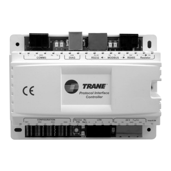
Installation Connectors layout RJ-45 COMM3 DIAG RS232 MODBUS RS485 Resistor Protocol Interface Controller Service CONFIGURATION 24 V Imax=0.5A Serv. BAS-SVX08D-E4... - Page 11 Installation Connector 1 Comm3 connection to Trane equipment 3-pole removable screw 5.08 mm connector Pins '1' & '2': Transmit and receive signals (no polarity) Pin 'SHD': Cable Shield Connector 2 USB connection to diagnostic PC USB type B female connector...
-
Page 12: Wiring Pic With Trane Equipment
Installation Wiring PIC with Trane equipment Wiring PIC with RTAC/ CGAN / CXAN / CGCL / CCUH / CCUN / CGWH / CGWN / RAUL / RTHD / CVGF / CGAM / CXAM / RTWD / RTUD chillers The following wiring diagram applies for units equipped with Tracer CH530 controller. -
Page 13: Wiring Pic With Rtaa/Rtab/Rtxa/Rtad/Rtwb/Rtra/Rtub Chillers (Ucm Cld Controller With Lci-C Interface)
Installation Wiring PIC with RTAA/RTAB/RTXA/RTAD/RTWB/RTRA/RTUB chillers (UCM CLD controller with LCI-C interface) The following wiring diagram applies for units equipped with Tracer UCM CLD controller with the LCI-C (A56) communication interface. RJ-45 COMM3 DIAG RS232 MODBUS RS485 Resistor UCM CLD LCI-C... -
Page 14: Wiring Pic With Rtaa/Rtab/Rtxa/Rtad/Rtwb/Rtra/Rtub Chillers (Ucm Cld Controller With Csr Interface)
Controller Service CONFIGURATION 24 V Imax=0.5A Serv. 24V AC/DC +6V/-12V Wiring PIC with CVGE/CVAE/RTHC chillers (UCP2 controller) The following wiring diagram applies for units equipped with UCP2 controller with the TCI4-Comm3 (A9) communication interface. RJ-45 COMM3 DIAG RS232 MODBUS RS485... -
Page 15: Ykd/Ykh Rooftop (Reliatel™ Controller)
Installation Wiring PIC with WSD/WSH/WKD/WKH/TSD/TSH/TKD/TKH/YSD/YSH/YKD/ YKH rooftop (Reliatel controller) The following wiring diagram applies for units equipped with Reliatel controller with the TCI communication interface. RELIATEL RJ-45 COMM3 DIAG RS232 MODBUS RS485 Resistor Protocol Interface Controller CONFIGURATION Service 24 V Imax=0.5A... -
Page 16: Wiring Pic With Modbus Building Management System
Installation Wiring PIC with Modbus Building Management System Wiring PIC with RS-232 Modbus BMS Common MODBUS BMS RS-232 1 2 3 4 5 6 7 8 9 RJ-45 COMM3 DIAG RS232 MODBUS RS485 Resistor Protocol Interface Controller Service CONFIGURATION 24 V Imax=0.5A... - Page 17 Installation If the RS485 wire length is less than 100 meters, it is recommended to use the termination resistor option. Set the 'Resistor' switch to the 'On' position. See following figure. MODBUS RS485 Resistor BAS-SVX08D-E4...
-
Page 18: Diagnostic Tool Installation
Step 0: Check if the diagnostic tool is already installed. From the 'Start' menu, 'All programs', check if the 'PIC Diag Tool' icon is located in the 'PIC Diag' program group. If the icon is present, the diagnostic tool is already installed. - Page 19 Installation Step 3: Confirm diagnostic tool installation Step 4: Select installation folder Once configured, click on 'Next'. BAS-SVX08D-E4...
- Page 20 Installation Step 5: Confirm installation parameters Once checked, click on 'Install'. The installation process starts copying files. Step 6: Finish the installation Click on 'Finish'. The software installation is done. BAS-SVX08D-E4...
-
Page 21: Diagnostic Cable
The diagnostic tool is ready to be used. Step 8: Launch the diagnostic tool The PIC must be connected to the PC prior to launch the diagnostic tool. From the 'Start Menu', 'All programs', 'PIC Diag' select the PIC application 'PIC Diag Tool'. -
Page 22: Operation
Operation Trane Equipment Data point List Table 4 - Data Point List for CVGF / CVHE / CVHF / CVHG chillers, Tracer CH530 controller Version 2.0 and greater Data Type Function Modbus Index Offset Point Description Unit 00001 Chiller Enable/Disable Command... -
Page 23: Data Point List For Rtac (Tracer Ch530)
Operation Table 5 - Data Point List for RTAC chillers (Chiller Profile), Tracer CH530 controller Data Type Function Modbus Index Offset Point Description Unit 00001 Chiller Enable/Disable Command (0=Disable) Binary 5/15 Outputs 00002 Chiller Mode (0=Cool) 40001 Copy of function 5/15 binary points bitfield 40002 Chilled Water Setpoint... - Page 24 Operation Table 6 - Data Point List for RTAC chillers (Public Extension), Tracer CH530 controller. Modbus Data Type Function Offset Point Description Unit Index 00001 Chiller Enable/Disable Command Binary 5/15 Outputs 00002 Chiller Mode 40001 Copy of function 5/15 binary points bitfield Analog 6/16...
-
Page 25: Data Point List For Rthd (Tracer Ch530)
Operation Table 7 - Data Point List for RTHD chillers, Tracer CH530 controller Data Type Function Modbus Index Offset Point Description Unit 00001 Chiller Enable/Disable Command (0=Disable) Binary 5/15 Outputs 00002 Chiller Mode (0=Cool) 40001 Copy of function 5/15 binary points bitfield 40002 Chilled Water Setpoint... -
Page 26: Data Point List For Rtwd / Rtud (Tracer Ch530)
Installation Table 8 - Data Point List for RTWD - RTUD chillers,Tracer CH530 controller Modbus Data Type Function Offset Point Description Unit Index 00001 Chiller Enable/Disable Command Binary 5/15 00002 Chiller Mode Outputs 00003 Noise Reduction Command (RTUD only) 40001 Copy of function 5/15 binary points bitfield 40002... - Page 27 Installation Table 9 - Data Point List for CGAN/CXAN/CGAM/CXAM/CGC/CCUH/CCUN/CGWH/CGWN/RAUL chillers, Tracer CH530 controller Data Type Function Modbus Index Offset Point Description Unit 00001 Chiller Enable/Disable Command (0=Disable) Binary 5/15 Outputs 00002 Chiller Mode (0=Cool) 40001 Copy of function 5/15 binary points bitfield 40002 Chilled Water Setpoint...
-
Page 28: Data Point List For Cgan/Cxan (Tracer Ch532 V1.2)
Operation Table 10 - Data Point List for CGAN/CXAN chillers, Tracer CH532 controller Version 1.2 Data Type Function Modbus Index Offset Point Description Unit 00001 Chiller Enable/Disable Command (0=Disable) 00002 Chiller Mode (0=Cool) Binary 5/15 Outputs 00003 Circuit 1 lockout 00004 Circuit 2 lockout 40001... -
Page 29: Data Point List For Cgan/Cxan (Tracer Ch532 V2.0)
Operation Table 11 - Data Point List for CGAN/CXAN chillers, Tracer CH532 controller Version 2.0 and greater Data Type Function Modbus Index Offset Point Description Unit 00001 Chiller Enable/Disable Command (0=Disable) 00002 Chiller Mode (0=Cool) Binary 5/15 Outputs 00003 Circuit 1 Enable/Disable 00004 Circuit 2 Enable/Disable 40001... - Page 30 Operation Table 12 - Data Point List for RTAA/RTAB/RTXA/RTAD/RTWB/RTRA/RTUB chillers, UCM CLD controller with LCI-C interface Data Type Function Modbus Index Offset Point Description Unit 00001 Chiller Enable/Disable Command (0=Disable) Binary 5/15 Outputs 00002 Chiller Mode (0=Cool) 40001 Copy of function 5/15 binary points bitfield 40002 Chilled Water Setpoint...
-
Page 31: Data Point List For Cgah/Cxah/Cgcl/Ccuh/Cgwh/Raul (Smm)
Operation Table 13 - Data Point List for CGAH/CXAH/CGCL/CCUH/CGWH/RAUL chillers, SMM controller Data Modbus Unit Function Offset Point Description Type Index 00001 1 = stop the circuit 1 00002 1 = stop the circuit 2 00003 1 = validation of the EVP leaving water setpoint Binary 00004 1 = unit runs in heating mode... - Page 32 Operation Table 13 - Continued Data Modbus Function Offset Point Description Unit Type Index 10026 1 = unit or circuit 1 automatic reset fault 10027 1 = unit or circuit 2 automatic reset fault 10028 1 = circuit 1 is limited or not ready 10029 1 = circuit 2 is limited or not ready 10030...
- Page 33 Operation Table 13 - Continued Data Modbus Unit Function Offset Point Description Type Index Bit 7 1 = compressor B2 runs Bit 6 1 = compressor A2 runs Bit 5 1 = default relay of circuit 1 is ON 30035 Bit 4 1 = EVP resistor is stopped Bit 3 1 = EVP water pump runs Bit 2 1 = liquid valve of circuit 1 open...
-
Page 34: (Ucm Cld + Csr)
Operation Table 14 - Data Point List for RTAA/RTAB/RTXA/RTAD/RTWB/RTRA/RTUB chillers, UCM CLD controller with CSR Data Modbus Function Offset Point Description Unit Type Index 00001 Enable remote setpoints 00002 Remote chiller auto/stop (0 = auto, 1 = stop) 00003 Enable Hot water setpoint 00004 Ice mode (1 = yes, 0 = no) Binary... - Page 35 Operation Table 14 - Continued Data Modbus Function Offset Point Description Unit Type Index 10041 Transition contactor 1 ( 1 = ON, 0 = OFF) 10042 Reset relay 2 ( 1 = ON, 0 = OFF) 10047 Oil line solenoid valve 2, female slide valve step load solenoid for 70-125 Ton ( 1 = ON, 0 = OFF) 10048 Transition contactor 2 ( 1 = ON, 0 = OFF)
- Page 36 Operation Table 14 - Continued Data Modbus Function Offset Point Description Unit Type Index 30022 Circuit 1 % airflow Percentage 30023 Circuit 2 % airflow Percentage 30024 % line voltage chiller Percentage 30025 Zone temperature Temperature 30026 Outdoor air temperature Temperature 30027 Compressor A phase A % RLA...
- Page 37 Operation Table 14 - Continued Data Modbus Function Offset Point Description Unit Type Index 30070 Compressor A operating mode None 30071 Compressor B operating mode None 30072 Compressor C operating mode None 30073 Compressor D operating mode None 30074 Slave EXV software revision level None 30075 COMM3 framing errors...
-
Page 38: Data Point List For Cvge/Cvae/Rthc Chillers (Ucp2 Controller)
Operation Table 15 - Data Point List for CVGE/CVAE/RTHC chillers, UCP2 controller Data Modbus Function Offset Point Description Unit Type Index Binary 5/15 00002 Tracer Chiller Auto/Stop (1 = auto, 0 = stop) Outputs 40001 Tracer Chilled Water Setpoint Temperature 40002 CTV/RTH: Tracer Current Limit Setpoint Percentage... - Page 39 Operation Table 15 - Continued Data Modbus Function Offset Point Description Unit Type Index 10036 external auto/stop 10037 emergency stop 10038 CTV: external free cooling Binary 10039 CTV/RTH: external ice making Inputs 10040 CTV: external heat pump 10041 Manual Chilled Water Pump (1= ON; 0 = AUTO) 10042 External Input Type (0 = 4-20mA;...
- Page 40 Operation Table 15 - Continued Data Modbus Function Offset Point Description Unit Type Index Bit 0 RESERVED Bit 1 RESERVED Bit 2 Tracer 30017 Bit 3 External Direct Capacity Control Bit 4 future 2 Bit 5 future 1 Bit 6 RESERVED Bit 7 Front Panel bitfield 30018...
- Page 41 Operation Table 15 - Continued Data Modbus Function Offset Point Description Unit Type Index 30042 CTV: Outboard Bearing Temp ABS: Strong Soln Temp Lvg LTHX Temperature 30043 CTV/RTH: Discharge Temp ABS: Intermd Soln Temp at Absorber Spray Temperature 30044 ABS: LiBr Concentration Percentage 30045 ABS: LiBr Cryst Temp...
- Page 42 Operation Table 15 - Continued Data Modbus Function Offset Point Description Unit Type Index HVAC Unit Type ID 0 = CVHE/G 1 = CVHF 2 = CVHB 3 = CVGE 30054 4 = CVAE 5 = RTHA 6 = RTHB 7 = two stage absorption 8 = one stage absorption 9 = direct fired absorption...
-
Page 43: Data Point List For Rooftops (Ucpii / Ucpiii And Reliatel Controllers)
Operation Table 16 - Data Point List for Rooftops, UCP2/UCP3 and Reliatel controllers Data Modbus Function Offset Point Description Unit Type Index 00001 ICS Diagnostic Reset (1 = Yes 0 = No) 00002 Factory Test (*** Factory Use Only ***) (1 = Yes 0 = No) 00003 ICS Slave Mode Requested (1 = Yes 0 = No) 00004... - Page 44 Operation Table 16 - Continued Data Modbus Function Offset Point Description Unit Type Index Bit 0 Compressor Lockout (Lockout Both) (1 = Not Locked Out 0 = Lock Out) Bit 1 Auxiliary Heat Lockout (1 = Not Locked Out 0 = Lock Out) Bit 2 Lead/Lag Enable/Disable (1 = Enabled 0 = Disabled) 40009 Bit 3 Zone Temperature Source (1 = Echelon 0 = Local)
- Page 45 Operation Table 16 - Continued Data Modbus Function Offset Point Description Unit Type Index 10048 Supply Air Tempering is Active (1 = Yes 0 = No) 10049 Exhaust Fan is Energized (1 = Yes 0 = No) 10050 Condenser Fan A is Energized (1 = Yes 0 = No) 10051 Condenser Fan B is Energized (1 = Yes 0 = No) 10052...
- Page 46 Operation Table 16 - Continued Data Modbus Function Offset Point Description Unit Type Index Bit 0 Compressor On or Off (1 = On 0 = Off) Bit 1 Compressor 2 Locked Out (1 = Yes 0 = No) Bit 2 HPC for Compressor 2 (1 = High Press 0 = Normal) 30020 Bit 3 Compressor 2 Cycling Input (1 = Normal 0 = Disabled) Bit 4 Compressor 2 Exists (1 = Yes 0 = No)
-
Page 47: Modbus Functions
Operation Modbus Functions Function 2: Read n bits Inputs are addressed starting at zero: input 10001 is addressed as 0. Function 4: Read n analog values Registers are addressed starting at zero: register 30001 is addressed as 0. Function 5: Write a bit Function 15: Write n bits Coils are addressed starting at zero: coil 00001 is addressed as 0. -
Page 48: Modbus Slave Address - Sw4
Operation Modbus slave address - SW4 To configure the PIC slave address (from 1 to 247), the dip switches SW4 should be configured according to the following table. Table 18 - SW4 - Modbus slave address SW4 - Modbus Slave Address... - Page 49 Operation Table 18 - Continued SW4 - Modbus Slave Address Address BAS-SVX08D-E4...
- Page 50 Operation Table 18 - Continued SW4 - Modbus Slave Address Address BAS-SVX08D-E4...
- Page 51 Operation Table 18 - Continued SW4 - Modbus Slave Address Address BAS-SVX08D-E4...
- Page 52 Operation Table 18 - Continued SW4 - Modbus Slave Address Address BAS-SVX08D-E4...
- Page 53 Operation Table 18 - Continued SW4 - Modbus Slave Address Address BAS-SVX08D-E4...
- Page 54 Operation Table 18 - Continued SW4 - Modbus Slave Address Address BAS-SVX08D-E4...
- Page 55 Operation Table 18 - Continued SW4 - Modbus Slave Address Address BAS-SVX08D-E4...
-
Page 56: Variable Format
Scaling = 1 Without unit: Offset = 0 Scaling = 1 PIC and Trane Equipment configuration Configure the PIC connected to a LON Trane Equipment Step 1: Configure PIC dip switches SW1 and SW2 according to the Trane Equipment CONFIGURATION BAS-SVX08D-E4... - Page 57 Operation Table 19 SW1 - Trane Equipment Configuration Trane Equipment Controller RTAC (Chiller Profile) CH530 CVGF CH530 RTHD CH530 CGAN / CXAN / CGCL / CCUH / CCUN / CGWH / CH530 CGWN / RAUL / CGAM / CXAM Reserved CGAN / CXAN CH532 V1.2...
- Page 58 Step 2: Validate the PIC configuration Once the PIC is configured and wired to Trane equipment, the configuration has to be validated. The PIC service pin has to be pressed for at least 15 seconds. That will save the configuration and reset the PIC. RJ-45...
-
Page 59: Configure The Pic Connected To A Comm3 Trane Equipment
Operation The PIC is now in a stand-by sequence, waiting for a Trane equipment to be identified. Step 3: Initiate communication between the PIC and Trane Equipment Once the PIC is in 'waiting' status, the existing Trane Equipment has to identify itself to the PIC by pressing once the Trane equipment service pin (See the Installation section for a more detailed view of the equipment service pin). - Page 60 Operation Table 21 SW1 - Trane Equipment Configuration Trane Equipment Controller CGAH / CXAH / CGCL / CCUH / CGWH / RAUL RTAA / RTAB / RTXA / RTAD / RTWB / RTRA / UCM CLD RTUB CVGE / CVAE / RTHC...
- Page 61 Step 2: Validate the PIC configuration Once the PIC is configured and wired to Trane equipment, the configuration has to be validated. The PIC service pin has to be pressed for at least 15 seconds. This will save the configuration and reset the PIC. RJ-45...
-
Page 62: Configuration Change
The PIC can start its communication sequence with Trane Equipment. Step 3: Configure Trane equipment In order to operate with the PIC, the Comm3 Trane Equipment must have its address set to '1'. See Installation Operation Maintenance manuals of the existing Trane equipment for details. - Page 63 Operation Diagnostic Tool Operations The PIC can be troubleshot using a diagnostic tool designed for the PIC. This tool provides information on: • Communication with Trane Equipment (counters) • Communication with Modbus device (counters) • Current configuration • Data point •...
-
Page 64: Maintenance
Maintenance PIC Status BAS-SVX08D-E4... - Page 65 - Tx Message Nb: Number of messages the PIC transmitted - Rx Message Nb: Number of messages the PIC received - Last Tx Message (sec): Time elapsed since the PIC sent the latest message - Last Rx Message (sec): Time elapsed since the PIC received the latest...
-
Page 66: Trane Equipment Communication Status
Maintenance Trane Equipment Communication Status The diagnostic tool provides the operator with an in-depth view of each communication channel. BAS-SVX08D-E4... - Page 67 • Equipment Configured Fail: The equipment indicates to the PIC that the Configuration operation has failed. • Subnet Node Query Status Fail: The PIC tries to ask to the equipment its subnet and node configuration and does not succeed. • Configuration Pass: The PIC auto-install processwas successful.
- Page 68 - Message sent: Number of messages the PIC transmitted - Message received: Number of messages the PIC received - Last message sent (sec): Time elapsed since the PIC sent the latest message - Last Message received (sec): Time elapsed since the PIC received the latest...
-
Page 69: Modbus Communication Status
Maintenance Modbus Communication Status BAS-SVX08D-E4... - Page 70 • Illegal Data Address (0x02): PIC has received a query for an unsupported data (not in the data point list) • Illegal Data Value (0x03): PIC has received a query with an illegal data value (out of range) • Slave Device Failure (0x04): Data table is not anymore updated but it has been updated at least once.
-
Page 71: Modbus Data Point Tables
Maintenance Modbus data point tables The diagnostic tool can display all four data types (analog inputs and outputs, binary inputs and outputs) in four separate screens. The diagnostic tool displays data in table. Data are displayed in decimal. BAS-SVX08D-E4... - Page 72 Maintenance The diagnostic tool displays data in table. Data are displayed in binary, 0 is OFF or FALSE, 1 is ON or TRUE. BAS-SVX08D-E4...
-
Page 73: Modbus Traffic
Maintenance Modbus Traffic The diagnostic tool offers the possibility to display and save the Modbus traffic between the PIC and the Modbus BMS. PIC displays Modbus frames in hexadecimal. BAS-SVX08D-E4... - Page 74 Maintenance Command description - Start Traffic: Displays Modbus frames - Start capture: Save Modbus frames - Clear: Clear the Modbus frames buffer in the diagnostic tool memory BAS-SVX08D-E4...
- Page 75 Field description - Rx>: Valid Modbus frame received by the PIC - Tx>: Modbus frame sent by the PIC ; Answer to the query of the BMS - *********************: Interruption in the traffic display. The operator switched to a different screen and then switched back to Modbus traffic screen.
- Page 76 Maintenance Data Point Description Table A - How to read Chiller Status in equipment data point lists Chiller Status - bitfield Item Register bit Description 0 (0000) = Chiller Off 1 (0001) = Chiller in start mode 2 (0010) = Chiller in run mode Chiller Run Mode Bits 0-3 3 (0011) = Chiller in pre-shutdown mode...
-
Page 77: Appendix
Appendix Table B - How to read Compressor Running Outputs in equipment data point lists Compressor Running Outputs - bitfield Bit Position Description Bit 15 Not used Bit 14 Not used Bit 13 Compressor F running (1=On) Bit 12 Compressor E running (1=On) Bit 11 Compressor D running (1=On) Bit 10... - Page 78 Notes BAS-SVX08D-E4...
- Page 79 Notes BAS-SVX08D-E4...
-
Page 80: Bas-Svx08D-E4
Literature Stocking Location Europe Trane has a policy of continuous product and product data improvement and reserves the right to change design and specifications without notice. Only qualified technicians should perform the installation and servicing of equipment referred to in this publication.