Trane Symbio 700 Controller Application Manual
With precedent packaged rooftop air-conditioners
Hide thumbs
Also See for Symbio 700 Controller:
- Troubleshooting manual (210 pages) ,
- Application manual (44 pages) ,
- User manual (20 pages)
Table of Contents
Advertisement
Quick Links
Application Guide
Symbio™ 700 Controller
with Precedent™ Packaged Rooftop
Air-Conditioners
Only qualified personnel should install and service the equipment. The installation, starting up, and servicing of heating, ventilating, and air-conditioning equipment
can be hazardous and requires specific knowledge and training. Improperly installed, adjusted or altered equipment by an unqualified person could result in death or
serious injury. When working on the equipment, observe all precautions in the literature and on the tags, stickers, and labels that are attached to the equipment.
July 2022
SAFETY WARNING
ACC-APG002A-EN
Advertisement
Table of Contents

Related Manuals for Trane Symbio 700 Controller


Summary of Contents for Trane Symbio 700 Controller
- Page 1 Application Guide Symbio™ 700 Controller with Precedent™ Packaged Rooftop Air-Conditioners SAFETY WARNING Only qualified personnel should install and service the equipment. The installation, starting up, and servicing of heating, ventilating, and air-conditioning equipment can be hazardous and requires specific knowledge and training. Improperly installed, adjusted or altered equipment by an unqualified person could result in death or serious injury.
- Page 2 Introduction Read this manual thoroughly before operating or servicing this unit. Warnings, Cautions, and Notices Safety advisories appear throughout this manual as required. Your personal safety and the proper operation of this machine depend upon the strict observance of these precautions. The three types of advisories are defined as follows: Indicates a potentially hazardous situation which, if not avoided, could result in death or WARNING...
- Page 3 Non-Trane personnel should always follow local regulations. Copyright This document and the information in it are the property of Trane, and may not be used or reproduced in whole or in part without written permission. Trane reserves the right to revise this publication at any time, and to make changes to its content without obligation to notify any person of such revision or change.
-
Page 4: Table Of Contents
Table of Contents Introduction..............7 Additional Documentation . - Page 5 Table of Contents Space Temperature Control..........23 Night Purge .
- Page 6 Table of Contents Service Test Mode — CVZT, VVZT, and VVDA ........39 Diagnostics.
-
Page 7: Introduction
Variable Volume Discharge Air (VVDA) These configurations can be used with standard cooling systems. This guide provides information about the configuration, control capabilities and troubleshooting of the Precedent system with Symbio 700 controller. Additional Documentation • BAS-SVN043*-EN: Quick Start Guide, Symbio™ Service and Installation App •... -
Page 8: Symbio 700 Overview
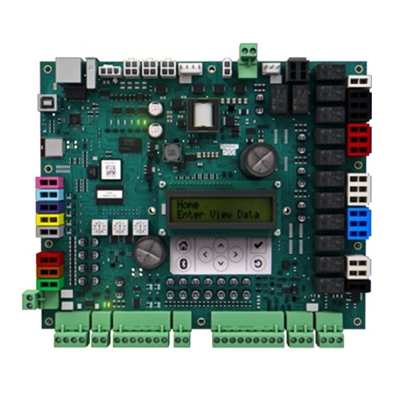
Symbio 700 Overview Field Connection The Symbio™ 700 controller optimizes inputs and outputs (I/O) for multiple applications. For initial installation of a Precedent with Symbio 700, the field landed inputs are outlined below. Figure 1. Symbio 700 Field Connections Table 1. Field Connections Signal Connector Function... -
Page 9: Unit Configuration
The Trane Symbio™ Service and Installation mobile app is required to setup, edit, and confirm the communication protocol and associated settings. The free download of Trane Symbio Service and Installation mobile app is available on the App Store® for iOS, and on Google Play® for Android™. - Page 10 Symbio 700 Overview Figure 3. Trane Symbio™ Service and Installation mobile app Bluetooth Pairing Quick Connection Instructions Follow these instructions to quickly connect the mobile app to the Symbio™ 700 controller: 1. Turn on Bluetooth® 2. Tap 3. Start the app. Tap View Available Devices.
- Page 11 Trane Connect username and password. 6. On the Unit List page, select the Symbio 700 controller that you want to pair with. If the controller is not listed, tap the refresh arrow in the upper right-hand corner of the screen.
- Page 12 Symbio 700 Overview – LonTalk® • Historical Alarms • Firmware Updates • Backup Restore For more detailed information on the Symbio Service and Installation Mobile Application, refer to Quick Start Guide, Symbio™ Service and Installation App (BAS-SVN043*-EN). ACC-APG002A-EN...
-
Page 13: Startup Sequence
Startup Sequence Under normal conditions, the Symbio 700 will startup over approximately 60 seconds once power is applied to the system. During this process, the controller checks that a valid system configuration is present and proceeds to normal control operation. After startup, the system will begin to respond to operational requests. -
Page 14: Conventional Thermostat Sequence Of Operation
Conventional Thermostat Sequence of Operation When the Precedent system is configured to operate with a conventional thermostat, the controller provides protection for the system (see General Support Sequence section) and continues to provide insight to operating conditions. A conventional thermostat can be applied with CVZT and single zone VAV configured systems. - Page 15 Conventional Thermostat Sequence of Operation ACC-APG002A-EN...
-
Page 16: Space Temperature Control
Space Temperature Control System Types of VVZT and CVZT operate to provide space comfort heating and cooling. A system mode wired input or Heat Cool Mode Request input determines the heating or cooling mode of operation. If a heat cool system mode input is not provided, the Symbio™ 700 operates per Heat Cool Mode Request default value, Auto is the default setting. -
Page 17: Single Zone Vav - Cooling
Space Temperature Control space temperature and discharge air temperature sensor are required input. If the discharge air temperature input becomes invalid, the control automatically reverts to Single Loop Space Temperature Control. Symbio™ 700 operates in Single Loop Space Temperature Control in heating modes when staged gas heat and staged electric heat are configured. -
Page 18: Cool - Economizer
Space Temperature Control Cool — Economizer If the unit is configured for a modulating outdoor air damper and conditions are suitable for economizer cooling, the supply fan will operate at minimum speed while the economizer damper modulates between the Outdoor Air Damper Minimum Position Setpoint and 100% to satisfy the discharge air temperature setpoint. -
Page 19: Variable Volume Discharge Air Control Sequence Of Operation
Variable Volume Discharge Air Control Sequence of Operation Variable Volume Discharge Air (VVDA) control uses available heating and cooling capacity to deliver the required temperature at the discharge of the unit. A discharge air temperature sensor is required for operation. In cooling modes, the control uses cooling sources to deliver air temperature as required by the Discharge Air Cooling Setpoint. -
Page 20: Duct Static Pressure High Limit
Variable Volume Discharge Air Control Sequence of Operation controller will modulate supply fan speed to maintain Duct Static Pressure relative to the Duct Static Pressure Setpoint. Duct Static Pressure High Limit The controller operates the supply fan to maintain duct static pressure below the Duct Static Pressure High Limit setpoint. -
Page 21: Heat Cool Modes
Heat Cool Modes Heat Cool Mode Status reports the unit mode of operation. The Symbio™ 700 can receive mode inputs from different external and local input sources that are arbitrated; however, the control active operating mode represents the capacity being delivered to the building and reported via Heat Cool Mode Status. The following modes of operation are supported. -
Page 22: Space Temperature Control
Morning Warm-up mode can also be commanded via Heat Cool Mode Request from a building automation system or external control. The Symbio 700 controller will continuously control space temperature to the morning warm-up setpoint until the mode is released or changed. -
Page 23: Vvda
Pre-Cool mode will terminate. Pre-Cool mode can also be commanded via Heat Cool Mode Request from a building automation system or external control. The Symbio 700 controller will continuously control space temperature to the Pre-Cool setpoint until the mode is released or changed. - Page 24 Heat Cool Modes Active. The supply fan operates at max speed on Constant Volume Units. Variable air volume discharge air control units will operate the supply fan to the duct static pressure setpoint and report Heat Cool Mode Status as Heat, if the installed heat type allows modulating air flow. Else if the heat type requires full air flow, Maximum Heat is reported.
-
Page 25: Dehumidification - Hot Gas Reheat
Dehumidification — Hot Gas Reheat Dehumidification control is a mode of Cooling when hot gas reheat is configured with a modulating reheat valve. Symbio™ 700 supports two configurable dehumidification methods: Dew Point (default) or Relative Humidity control for occupied and unoccupied operation. All unit types require a valid space relative humidity, space temperature, discharge air temperature sensor and Evaporator Entering Refrigerant Temperature for dehumidification operation. -
Page 26: Relative Humidity - Termination
Dehumidification — Hot Gas Reheat • Space Dew Point is less than the Space Dew Point Unoccupied Setpoint – Dew Point Setpoint Offset or • Outdoor Air Dew Point is less than the Outdoor Air Dew Point Setpoint – Dew Point Setpoint Offset •... -
Page 27: Heat Types
Heat Types Two heating types are supported, staged electric and staged gas heat. Space temperature control variable speed and multi-speed fan units will increase supply fan speed with increased heating capacity. Multi-Zone VAV units with staged heat will always operate the supply fan at full airflow, see Maximum Heat, in Heat Cool Modes section for details. -
Page 28: Outdoor Air Damper Control
Outdoor Air Damper Control Economizer Cooling Symbio™ 700 supports a 0 to 100% economizer damper which requires a discharge air temperature sensor to be installed for economizer cooling. There are four configurable economizer types: fixed dry bulb, differential dry bulb, reference enthalpy, and comparative enthalpy. Each type, enable, and the high limit disable criteria are defined as follows. -
Page 29: Ventilation Control
Outdoor Air Damper Control Table 5. Sensor data (continued) Required Sensor Data Economizer Enable Method Return Air Temperature When conditions are suitable for economizer operation, the outdoor air damper modulates between a calculated outdoor air damper minimum position (based on Supply Fan Compensation and Demand Controlled Ventilation) and 100% open. -
Page 30: Remote Minimum Position Control
Outdoor Air Damper Control Remote Minimum Position Control With an installed Customer Connection Module and Remote Minimum Position is configured in the Symbio™ 700, a wired potentiometer can be used to adjust the outdoor air damper minimum position setpoint in the range of 0 to 50%. The setting is reported via Remote Minimum Position. If Remote Minimum Position input and Demand Controlled Ventilation is installed, the Remote Minimum Position provides the minimum damper position setpoint at full fan capacity. - Page 31 Outdoor Air Damper Control Table 6. 0 to 100% economizer – variable speed supply fan (continued) Supply Fan Demand Remote Occupancy Outdoor Air Damper Controlling Setpoints Controlled Minimum Compensa- Status tion Ventilation Position DCV Minimum OA Damper Position at Mid Fan Capacity DCV Minimum OA Damper Position at Min Fan Capacity Remote Minimum Position (Full Fan Capacity) Occupied,...
-
Page 32: To 50% Motorized Damper
Outdoor Air Damper Control Table 7. 0 to 100% economizer – multi-speed supply fan (2–speed) (continued) Supply Fan Demand Remote Occupancy Outdoor Air Damper Controlling Setpoints Controlled Minimum Compensa- Status tion Ventilation Position Supply Fan at 100%: Occupied, Design Minimum OA Damper Position at Full Fan Capacity Not Installed Occupied Enabled... -
Page 33: General Support Sequences
General Support Sequences Fan Setpoints with ERM-driven Fan Types When a system is equipped with an External Rotor Motor (ERM), the minimum and maximum ERM parameters can be adjusted to tune the airflow to meet the application requirements. In addition to this, the Symbio™ 700 supports setpoints that can adjust airflow as needed: •... -
Page 34: Compressor Low Pressure Cutout Control
General Support Sequences Refer to the Diagnostics section for specific diagnostics generated based on the Compressor Proving signals. Compressor Low Pressure Cutout Control For each compressor/circuit, a normally CLOSED low pressure cutout input is monitored for equipment protection on the Symbio™ 700. When a low pressure event is active, the input becomes OPEN and diagnostics are generated as described below. -
Page 35: Evaporator Defrost Control
Evaporator Defrost Control To prevent frost build-up on the indoor coil during low ambient conditions, compressor operation is monitored and controlled accordingly, relative to outdoor air temperature. Evaporator Defrost Control can be initiated through two means, based on the FroStat input. FroStat Installed (default): •... -
Page 36: Building Automation System Support Sequences
Building Automation System Support Sequences Occupancy Mode During expected occupied periods, the system will control to the user selected cooling and heating setpoints. • The unoccupied setpoint temperatures are often adjusted higher for cooling (setup) and lower for heating (setback) to reduce building operating cost. •... -
Page 37: Capacity Limit Control
Building Automation System Support Sequences – Compressors – Condenser fans – Unloader solenoids – Heat stages • All equipment control analog outputs are set to their minimum/off command values. • All communicating devices, such as supply fans, are commanded to their off state. •... -
Page 38: Emergency And Ventilation Override
Building Automation System Support Sequences All equipment safeties and limitations will be in-place while the Remote Capacity Control functions are being leveraged: • Minimum fan speeds as defined per active capacity will be maintained • Compressor Minimum ON/OFF times will be maintained •... -
Page 39: Service Test Mode
Service Test Mode Service Test Mode can be used to initiate certain operating modes of the equipment. Refer to the following sections for more details associated with this feature. Service Test Timeout Service Test Timeout (Minute) is a user selected time value. Once Service Test Mode has been initiated, and this timer expires, the controls are forced to leave Service Test Mode and return to normal unit operation. - Page 40 Service Test Mode ACC-APG002A-EN...
- Page 41 Service Test Mode ACC-APG002A-EN...
-
Page 42: Diagnostics
If the Filter Runtime hours exceed the value set by the user for the Filter Runtime Hours Setpoint, the Symbio 700 controller activates the Diagnostic: Maintenance Required point. If for any reason it is required to reset the component statistical data, the Run Time Reset or Starts Reset points can be accessed through the Symbio Service and Installation mobile app.. -
Page 43: Diagnostic: Compressor X Contactor Failure
Diagnostics • All compressors on the associated circuit are de-energized immediately and they are locked out until a Reset Diagnostic action is initiated. • The “Diagnostic: Compressor X Proving Lockout” diagnostic point is activated and the alarm output is activated. Diagnostic: Compressor X Contactor Failure If a compressor proving input becomes Active for 5 continuous seconds when the associated compressor command output is Inactive, a Diagnostic: Compressor X Contactor Failure is generated... -
Page 44: Diagnostics - Alarm Indicator Status
Diagnostics Diagnostics – Alarm Indicator Status Symbio™ 700 will support an Alarm Indicator Status point that if configured, drives the state of a relay output on the Customer Connection Module. This point is set to active when a failure occurs that functionally stops a critical component within the HVAC system. -
Page 45: Troubleshooting
Troubleshooting The Symbio™ 700 controller provides system shutdown, operational default operation, and communication error handling of the Odyssey unit. The list of fault conditions below will stop normal operation or change the operation of the unit to a default condition. Faults are indicated in the Active Alarm menu of the onboard user interface and the Symbio Service and Installation mobile app. -
Page 46: Sensor Fault
Troubleshooting Sensor Fault On Symbio™ 700, if a sensor value goes outside of its minimum or maximum range, the point goes into an Alarm State. If the point in the Alarm State, we consider the sensor failed and take the following actions: Fault Symbio 700 Response... -
Page 47: Supply Fan Fault
Troubleshooting Fault Symbio 700 Response Response Type LPC Lockout For specific operation associated with the LPC Manual Reset diagnostics, refer to the Compressor Protection section of this document. Proving Lockout For specific operation associated with the proving Manual Reset diagnostics, refer to the Compressor Protection section of this document. -
Page 48: Staged Gas Heat Fault
Troubleshooting Symbio 700 Response Response Type Failure Failure Detection • Diagnostic: ERM Supply The Rectifier thermocouple Fan Power Mod has reached a too-high Overheated – 2 will be Diagnostic: ERM Supply Fan Auto Reset temperature. (Motor Manual set to “Active” Power Mod Overheated - 2 Reset) •... -
Page 49: Economizer Fault
Troubleshooting Fault Fault Detection Symbio 700 Response Response Type Diagnostic: IGN1 Flame Gas Heat Ignition Module via Status Only (Ignition Module Lockout) Auto Reset Sensed w/Gas Valve Off Modbus • All heating operation is terminated/ Diagnostic: IGN1 Hardware Gas Heat Ignition Module via disabled Auto Reset Configuration Error... - Page 50 Troubleshooting • FDD: Excessive Outdoor Air In minimum ventilation mode and the damper feedback position is >10% of the damper commanded value for 5 continuous minutes. • FDD: Outdoor Air Damper Not Modulating In minimum ventilation mode and the damper feedback is <10% of the damper commanded value for 5 continuous minutes.
-
Page 51: Supply Fan
Appendix A Supply Fan Multi-Speed/ERM Table 11. Multi-speed supply fan speeds (three stages of cooling) Unit Operation Supply Fan Speed (%) Fan Only Cooling Stage 1 Cooling Stage 2 Cooling Stage 3 Electric/Gas Heat 1 Electric/Gas Heat 2 Table 12. Multi-speed supply fan speeds (four stages of cooling) Unit Operation Supply Fan Speed (%) Fan Only... -
Page 52: Variable Speed/Erm - Discharge Air Temperature Control
Appendix A Table 14. Variable speed space temperature control supply fan speeds (four stages of cooling) (continued) Unit Operation Minimum Supply Fan Speed (%) Cooling Stage 1 Cooling Stage 2 Cooling Stage 3 Cooling Stage 4 Electric/Gas Heat 1 Electric/Gas Heat 2 100% Variable Speed/ERM —... -
Page 53: Cooling Only (Electric Heat) - Cvzt & Vvzt
Appendix A Cooling Only (Electric Heat) – CVZT & VVZT Table 17. Dual compressor cooling staging (manifold) Unit Operation Unit Response Cool Stage 1 Compressor 1 Output ON Cool Stage 2 Compressor 2 Output ON Cool Stage 3 Compressor 1 Output ON + Compressor 2 Output ON Table 18. -
Page 54: Gas Heat
Appendix A Gas Heat Table 23. Gas heat staging Unit Operation Unit Response Gas Heat Stage 1 Gas Valve Stage 1 ON Gas Heat Stage 2 Gas Valve Stage 2 ON Diagnostics and Alarm Indicator Status Table 24. Supported diagnostics and alarm relay functionality Diagnostic/Alarm Alarm Indicator Diagnostic: Unit Communications Failure... - Page 55 Appendix A Table 24. Supported diagnostics and alarm relay functionality (continued) Diagnostic/Alarm Alarm Indicator Diagnostic: Circuit 2 LPC Trip Diagnostic: Comp 1 Proving Trip Diagnostic: Comp 2 Proving Trip Diagnostic: Maintenance Required Discharge Air Temperature Local Outdoor Air Temperature Active Outdoor Air Humidity Active Space CO2 Concentration Active Space Humidity Active...
-
Page 56: Emergency And Ventilation Override
Appendix A Emergency and Ventilation Override Table 25. Emergency and ventilation override Inputs Outputs Compres- Compres- Heat Cool Supply Fan Supply Fan Auxiliary Emergency Override sor Cool sor Heat Mode On/Off Speed Heat Stage Stage Stage Status Request Request Request Request Request Point... -
Page 57: Dual Setpoint
Appendix A • Heating setpoint low limit • Cooling setpoint high limit • Cooling setpoint low limit These setpoint limits apply only to the occupied and occupied standby, heating, and cooling setpoints. They do not apply to the unoccupied heating and cooling setpoints. When the controller is in the unoccupied mode, it always uses the unoccupied heating and cooling setpoints. - Page 58 Notes ACC-APG002A-EN...
- Page 59 Notes ACC-APG002A-EN...
- Page 60 For more information, please visit trane.com or americanstandardair.com. Trane and American Standard have a policy of continuous product and product data improvement and reserve the right to change design and specifications without notice. We are committed to using environmentally conscious print practices.