Advertisement
Quick Links
www.delta.com.tw/products/plc.asp
Compact, Multi-function,
DVP-SA
Multiple Commands PLC
1
WARNING
This Instruction Sheet only provides descriptions for electrical specifications, general specifications, installation &
wiring, troubleshooting and peripherals. Other detail infromation about programming and commands is compatible
with EP series; please see PLC Application Manual. For more information about the optional peripherals , please
see individual product manual.
This is an OPEN TYPE PLC. The PLC should be kept in an enclosure away from airborne dust, humidity, electric
shock risk and vibration. Also, it is equipped with protective methods such as some special tools or keys to open
the enclosure, so as to avoid the hazard to users and the damage to the PLC.
Never connect the AC main circuit power supply to any of the input/output terminals, as it will damage the PLC.
Check all the wiring prior to power up. To avoid any electromagnetic noise, make sure the PLC is properly
grounded
.
2
INTRODUCTION
2.1 Model Name Explanation and Peripherals
Thank you for choosing DELTA's PLC DVP series. The
Nameplate Explanation
DVP-SA series has a 12-points (8 input points + 4
outputs) PLC main processing unit with multiple
PLC Model
commands for use. It also has an 8K Steps program
Input Power Supply Spec.
Output Module Spec.
memory to connect to every SS series expansion unit,
Barcode and Serial Number
CPU Version
including digital I/O (Maximum 112 Input / 112 Output
expansion points), analog module, etc. for various
applications. Its power unit is separated from the MPU
for better space utilization and easier installation.
Model Name
Serial Number
Series Name
Points (8 inputs + 4 outputs)
SA Series
R: Relay
T: Transistor
DC Power Input
Peripherals
◎ DVPHPP02: Handheld Programming panel
◎ WPLSoft: Windows Ladder Logic Programming Software
◎ DVPACAB115: 1.5M Cable (HPP
PLC, included in DVPHPP02)
◎ DVPACAB215: 1.5M Cable (PC (DB9+DB25)
PLC)
◎ DVPACAB230: 3.0M Cable (PC (DB9+DB25)
PLC)
◎ DVPACAB2A30: 3.0M Cable (PC (DB9)
PLC)
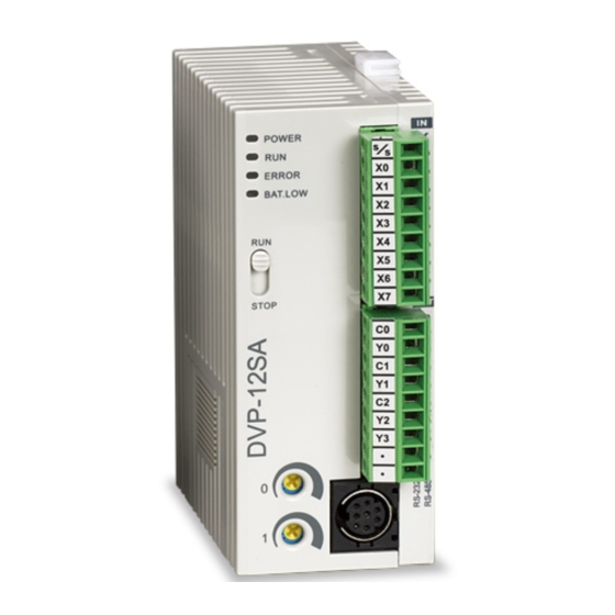
2.2 Product Profile and Outline
POWER
RUN
ERROR
RUN
Y0
C1
Y1
C2
Y2
Y3
Units :mm
※ Battery replacement: Please change the battery within 3 minutes, or
the internal data of the PLC (including the program area, perpetual
calendar and latched registers) could be lost or destroyed.
3
FUNCTION SPECIFICATIONS
Items
Control Method
I/O Processing Method
Execution Speed
Program language
Program Capacity
Commands
X External input relay
Instruction Sheet
Y External output relay
General
Auxiliary
Latched
M
Relay
Special
100ms
T
Timer
10ms
1ms
16-bit count up
32-bit count
C Counter
up/down
32bit
high-speed
count up/down C251~C254, 2 phase 2 input, 3 points (*3)
Initial step point S0~S9, 10 points (*1)
Zero point
MODEL :
DVP12SA11R
reset
Step
S
POWER INPUT
: 24DC 6W MAX
point
General
OUTPUT MODULE : 2.0A 250Vac 50/60Hz RES. LOAD
Latched
V1.00
1 2 SA11R 0T402 00 01
Alarm
Current value of the
DELTA ELECTRONICS INC.
MADE IN XXXXXX
T
timer
Current value of the
C
counter
General
Data
Latched
D
Produ ction nu mber
register
Produ ction we ek
Special
Produ ction Yea r 20 04
Index
Produ ction fa ct ory
Version typ e
File register
Produ ction mod el
For master control
N
nested loop
P For CJ, CALL commands P0~P255, 256 points
External interrupt
I
Time interrupt
Hi-speed counter
Communication
K Decimal
1 Status indicator: POWER, RUN,
ERROR, BAT.LOW
H Hexadecimal
2 RUN/STOP switch
Programming port
3 VR0: M1178 Start-up/D1178
Analog Volume / Perpetual
Corresponding value
Calendar (RTC)
4 VR1: M1179 Start-up/D1179
corresponding value
Special Expansion Module
5 DIN rail clip
*1: The non-latched area is fixed, and can't be changed.
6 I/O terminals
*2: The non-latched area can be changed to a latched area with parameter setting.
7 I/O point indicators
*3: The latched area can be changed to a non-latched area with parameter setting.
*4: The latched area is fixed, and can't be changed.
8 COM1 (RS-232) (Rx) indicator
9 COM2 (RS-485) (Tx) indicator
M
10 COM1 (RS-232) programming port
Auxiliary
Relay
11 Nameplate
Non-latched (fixed)
12 Expansion port
T
13 Mounting hold of the expansion unit
Timer
14 DIN rail (35mm)
Non-latched (fixed)
15 Expansion unit clip
C0~C95
16 COM2 (RS-485) Communication
C
port
Counter
Non-latched
17 DC Power input
(fixed)
18 RS-485 Cable (standard accessory)
19 Power input cable (standard
D
accessory)
Register
20 Battery Cover
Non-latched (fixed)
21 Battery socket connection
22 Battery mount
File Register
※ When switching between power On/Off or MPU RUN/STOP modes:
Specifications
Stored program, cyclic scan system
Batch processing method (when END command
I/O refresh command is available
is executed)
Application Commands
Basic commands (several us)
(10~hundreds us)
Commands + Ladder Logic + SFC
Including the Step commands
7920 STEPS
SRAM + Battery
32 Basic sequential commands (including
168 Application commands
STL/RET)
X0~X177, octal number system, 128
Total
Correspond to external input point
points
256
Y0~Y177, octal number system, 128
points Correspond to external output point
points
M0~M511, 512 points (*1)
M512~M999, 488 points (*3)
Total
Contacts can switch to On/Off in
M2000~M4095, 2096 points (*3)
4096
program
M1000~M1999, 1000 points (some are
points
latched)
T0~T199, 200 points (*1)
T192~T199 for Subroutine
When the timer that set by TMR
Total
T250~T255, 6 points Accumulative (*4)
command reaches the preset value,
256
T200~T239, 40 points (*2)
the T contact with the same number
points
will be On.
T240~T245, 6 points Accumulative (*4)
T246~T249, 4 points Accumulative (*4)
C0~C95, 96 points (*1)
C96~C199, 104 points (*3)
When the counter that set by CNT
C200~C215, 16 points (*1)
Total
(DCNT) command reaches the
C216~C234, 19 points (*3)
250
preset value, the C contact with the
points
C235~C242, 1 phase 1 input, 9 points (*3)
same number will be On.
C246~C249, 1 phase 2 input, 3 points (*3)
Usage device of step ladder diagram
S10~S19, 10 points (use with IST
Total
(SFC)
command) (*1)
1024
Latched Range:
S20~S511, 492 points (*1)
points
Start: D1214 (K512)
S512~S895, 384 points (*3)
End: D1215 (K895)
S896~S1023, 124 points (*3)
When the timer reaches the preset
T0~T255, 256 points
value, the contact of timer will be On.
C0~C199, 16-bit counter, 200 points
When the counter reaches the
preset value, the contact of counter
C200~C254, 32-bit counter, 50 points
will be On.
D0~D199, 200 points (*1)
D200~D999, 800 points (*3)
Total
Can be memory area for storing
D2000~D4999, 3000 points (*3)
5000
data. E and F can be used as the
points
special purpose of index indication.
D1000~D1999, 1000 points
E0~E3, F0~F3, 8 points (*1)
0~1599 (1600 points) (*4)
Expansion register for storing data.
Control point of master control
N0~N7, 8 points
nested loop
The location point of CJ, CALL.
I001 (X0), I101 (X1), I201 (X2), I301 (X3), I401
(X4), I501 (X5); 6 points (all are rising-edge
trigger)
The location pointer of interrupt
I6□□ (1ms), I7□□ (1ms), (□□=1~99ms)
subroutine
I010, I020, I030, I040, I050, I060; 6 points
I150, 1 point
K-32,768 ~ K32,767 (16-bit operation)
K-2,147,483,648 ~ K2,147,483,647 (32-bit operation)
H0000 ~ HFFFF (16-bit operation), H00000000 ~ HFFFFFFFF (32-bit operation)
COM1: RS-232, COM2: RS-485 (Master/Slave), They can be used at the same time.
MPU built-in 2 points VR / MPU built-in RTC
Use the same modules (AD, DA, PT, TC, XA, RT) of SS series. (Max. 8 Expansion Unit
points)
General
Latched
Special auxiliary relay
M0~M511
M512~M999
M1000~M1999
Latched (default)
Some are latched and
Start: D1200 (K512)
can't be changed
End: D1201 (K999)
100 ms
10 ms
10ms
1 ms
T0 ~T199
T200~T239
T240~T245
T246~T249
Non-latched (fixed)
Accumulative Latched (fixed)
16-bit count up
32-bit count up/down
32-bit high-speed count up/down
C96~C199
C200~C215
C216~C234
C235~C245
Latched (default)
Latched (default)
Non-latched
Start: D1208 (K96)
Start: D1210 (K216)
Start: D1212 (K235)
(fixed)
End: D1209 (K199)
End: D1211 (K234)
End: D1213 (K255)
General
Latched
Special registers
D0~D199
D200~D999
D1000~D1999
Factory setting is latched.
Some are latched and
Start: D1216 (K200)
can't be changed.
End: D1217 (K999)
K0~K1599
Latched (fixed)
POWER
Remarks
Memory Type
STOP RUN
Off On
Non-latched
Clear
Unchanged
Latched
Unchanged
Special M, Special
Initial value
D, Index register
File register
4
Model
DVP12SA11R/T DVP08SM11N
Item
MPU: 24VDC (-15%~20%) (with DC input reverse polarity protection),
Power supply voltage
Expansion Unit: supplied by the MPU
Fuse
2A / 250VAC
Power Consumption
6W
Insulation Resistance
ESD: 8KV Air Discharge
EFT: Power Line: 2KV, Digital I/O: 1KV, Analog & Communication I/O: 250V
Noise Immunity
Damped-Oscillatory Wave: Power Line: 1KV, Digital I/O: 1KV
RS: 26MHz~1GHz, 10V/m
The diameter of grounding wire cannot be smaller than the wire diameter of
Grounding
terminals L and N (All DVP units should be grounded directly to the ground pole).
Operation: 0℃~55℃ (Temperature), 50~95% (Humidity), Pollution degree 2;
Environment
Storage: -25℃~70℃ (Temperature), 5~95% (Humidity)
Vibration / Shock Resistance
Standard: IEC1131-2, IEC 68-2-6 (TEST Fc) / IEC1131-2 & IEC 68-2-27 (TEST Ea)
Weight (approx.) (g)
158
Input Point Electrical Specification
Input Type
DC (SINK or SOURCE)
Input Current 24VDC 5mA
Off→On, above16VDC
Active Level
On→Off, below
14.4VDC
About 10ms (An
adjustment range of
Responding
0~10,000ms could be
Time
selected through D1020
and D1021)
5
MODEL NAME & I/O CONFIGURATION
◎ Standard MPU
Input / Output
Model
Input Unit
Power
Point
DVP12SA11R
8
DC Sink or
24VDC
Source
DVP12SA11T
8
6
6.1 PLC Mounting Arrangements and Wiring Notes
Installation of the DIN rail
The DVP-PLC can be secured to a cabinet by using the
DIN rail that is 35mm high with a depth of 7.5mm. When
mounting the PLC on the DIN rail, be sure to use the end
bracket to stop any side-to-side motion of the PLC, thus to
Latched
reduce the chance of the wires being pulled loose. At the
M2000~M4095
bottom of the PLC is a small retaining clip. To secure the
Latched (default)
PLC to the DIN rail, place it onto the rail and gently push
Start: D1202 (K2000)
up the clip. To remove it, pull down the retaining clip and
End: D1203 (K4095)
gently pull the PLC away from the DIN rail. As shown on
100 ms
T250~T255
the right:
Wiring
Notes:
22-16AWG
1 Please use 22-16AWG (1.5mm) wiring (either single or multiple core) for I/O
C246~C255
wiring terminals. The specification for the terminals is as shown on the left. PLC
Latched (default)
terminal screws should be tightened to between 5~8 kg-cm (4.3~6.9 in-lbs).
2 I/O signal wires or power supply should not run through the same multi-wire
<1.5mm
cable or conduit.
Latched
6.2 Wiring Notes
D2000~D4999
Environment
Factory setting is latched.
1. DO NOT store the PLC in an atmosphere that is dusty, smoky, with metallic debris or corrosive or flammable gases.
Start: D1218 (K2000)
2. DO NOT store the PLC in an environment with high temperature or high humidity.
End: D1219 (K4999)
3. DO NOT install the PLC on a shelf or on an unstable surface.
Power Input Wiring
DVP-SA series input power supply is DC input. Please take a note of listed items when operating DVP-SA.
Series.
Clear all M1031
Clear all M1032
Factory
RUN STOP
non-latched area
latched area
Setting
M1033=Off, clear
M103=On,
Clear
Unchanged
0
unchanged
Unchanged
Clear
0
Initial
Unchanged
Unchanged
value
Unchanged
0
ELECTRICAL SPECIFICATIONS
DVP08SN11R/T DVP08SP11R/T DVP16SP11R/T
-
5W
5W
8W
8W
> 5 MΩ at 500 VDC (Between all inputs / outputs and earth)
128
154 /146
141 /136
162 /154
Output Point Electrical Specification
Output Type
Relay-R
Transistor-T
Current
0.3A/1 point @ 40℃; When the output
1.5A/1 point
Specification
of Y0 and Y1 is high-speed pulse, Y0
(5A/COM)
and Y1 = 30mA
Voltage
Below 250VAC,
30VDC
Specification
30VDC
75VA
When the output of Y0 and
Maximum
(Inductive)
Y1 is high-speed pulse, Y0
9W/1 point
Loading
and Y1 = 0.9W (Y0 =
90 W
32kHz, Y1 = 10kHz)
(Resistive)
Off→On
Responding
20us
Y0 and Y1 are specified
About 10 ms
Time
On→Off
points for high-speed pulse
30us
Profile
Output Unit
I/O Configuration
reference
Type
Point
Type
S/S
X0
X1
X2
4
Relay
X3
X4
X5
X6
X7
C0
Y0
C1
Y1
4
Transistor
C2
Y2
Y3
INSTALLATION & WIRING
When installing the DVP
series PLC, make sure that it is
installed in an enclosure with
sufficient
space
(as
shown
below) to its surroundings so as
to allow heat dissipation.
D
D
D
DVP
M P
D
D > 50 mm
Advertisement

Related Manuals for Delta DVP-SA


Summary of Contents for Delta DVP-SA
- Page 1 22 Battery mount Power Input Wiring File Register Latched (fixed) FUNCTION SPECIFICATIONS DVP-SA series input power supply is DC input. Please take a note of listed items when operating DVP-SA. ※ When switching between power On/Off or MPU RUN/STOP modes: Series.
- Page 2 Explanation Code Explanation DC Type 24VDC DVP-SA series provides the expansion units with different I/O points to extend input point X and output point Y. (DC Signal IN) Device S exceeds the usage C register exceeds the usage 0001 0E04...