Table of Contents
Advertisement
Quick Links
Instructions and Parts List
3M-Matic
a80b
Type 10800
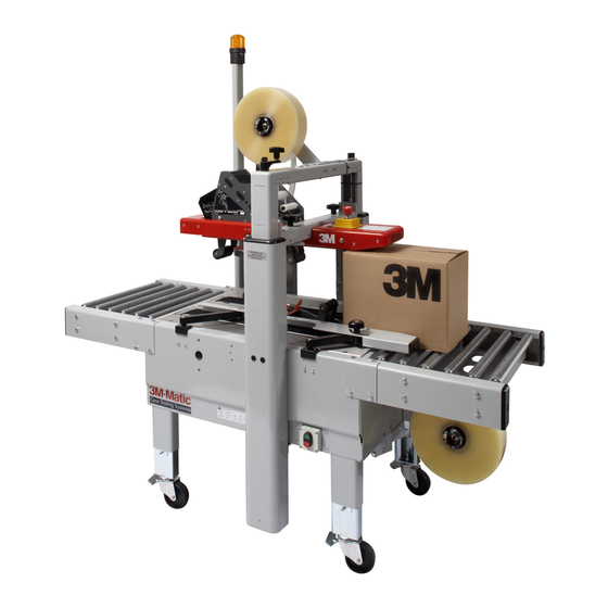
Adjustable
Case Sealer
with
AccuGlide 2+
Taping Heads
Serial No.
For reference, record machine serial number here.
3M Industrial Adhesives and Tapes
3M Center, Building 220-5E-06
St. Paul, MN 55144-1000
™
™
Important Safety
Information
BEFORE INSTALLING
OR OPERATING THIS
EQUIPMENT
Read, understand, and
follow all safety and
operating instructions.
Spare Parts
It is recommended you
immediately order the
spare parts listed in the
"Spare Parts/Service
Information" section.
These parts are expected
to wear through normal
use, and should be kept
on hand to minimize
production delays.
"3M-Matic"and "AccuGlide" are Trademarks of,
3M St. Paul, MN 55144-1000
Printed in U.S.A.
© 3M 2011 44-0009-2069-2 (C060311-NA)
Advertisement
Table of Contents

Related Manuals for 3M 3M-Matic a80b


Summary of Contents for 3M 3M-Matic a80b
- Page 1 Serial No. For reference, record machine serial number here. "3M-Matic"and "AccuGlide" are Trademarks of, 3M Industrial Adhesives and Tapes 3M St. Paul, MN 55144-1000 3M Center, Building 220-5E-06 Printed in U.S.A.
- Page 2 Adjustable case sealer. 3M-Matic 3M Industrial Adhesives and Tapes 3M Center, Building 220-5E-06 St. Paul, MN 55144-1000 Edition April 2011 Copyright 3M 2011...
-
Page 3: Replacement Parts And Service Information
Included with each machine is an Instructions and Parts List manual. Technical Assistance / Replacement Parts and Additional Manuals: Call the 3M-Matic™ Help line at 1-800 328-1390. Provide the customer support coordinator with the model/machine name, machine type, and serial number that are located on the identifi cation plate (For example: Model a80b - Type 10800 - Serial Number 13282). - Page 4 THIS PAGE IS BLANK...
-
Page 5: Table Of Contents
TABLE OF CONTENTS - MANUAL 1: a80b Adjustable Case Sealer (For Taping Head Information - See MANUAL 2: AccuGlide™ 2+ STD 2 Inch Taping Head) a80b Adjustable Case Sealer Page Cover Page Replacement Parts and Service Information ............... i - ii Table of Contents ......................... - Page 6 THIS PAGE IS BLANK...
- Page 7 TABLE OF CONTENTS (continued) 5. Shipment, Handling, and Storage 5.1 Packed Machine Shipment and Handling ................15 5.2 Overseas Shipment Packaging (Optional) ................15 5.3 Handling and Transportation of Uncrated Machine ............. 15 5.4 Machine Storage ......................... 15 6. Unpacking 6.1 Uncrating and Removal of Pallet ..................
- Page 8 THIS PAGE IS BLANK...
- Page 9 TABLE OF CONTENTS (continued) 12. Operation 12.1 Operator’s Correct Working Position ................24 12.2 Starting the Machine ....................... 24 12.3 Starting Production ......................24 12.4 Tape Replacement ......................24 12.5 Box Size Adjustment ....................... 24 12.6 Cleaning .......................... 24 12.7 Table of Adjustments ....................... 24 12.8 Safety Devices Inspection ....................
- Page 10 ABBREVIATIONS AND ACRONYMS LIST OF ABBREVIATIONS, ACRONYMS 3M-Matic - Trademark of 3M St. Paul, MN 55144-1000 AccuGlide - Trademark of 3M St. Paul, MN 55144-1000 Scotch - Trademark of 3M St. Paul, MN 55144-1000 Drw. - drawing - for example Figure - exploded view fi...
-
Page 11: Introduction
1-INTRODUCTION 1.1 Manufacturing Specifi cations / Description / Intended Use The 3M-Matic 2+ Taping Heads is designed a80b Adjustable Case Sealer with AccuGlide to apply a “C” clip of Scotch pressure-sensitive fi lm box sealing tape to the bottom center seam ®... -
Page 12: How To Read And Use The Manual / Reference Documents
1.2.3 Consulting the Manual Center, Bldg. 220-5E-06 St. Paul, MN 55144-1000 The manual is composed of: (USA) / Edition April 2011 / Copyright 3M 2011 / All rights reserved. The manufacturer reserves the right - Pages which identify the document and the machine to change the product at any time without notice. -
Page 13: General Information
2-GENERAL INFORMATION 2.1 Data Identifying Manufacturer and Machine For Industrial Use Only 2011 April a80b-NA... -
Page 14: Warranty / Contents
3M’s factory or an authorized service station designated by 3M. A part will be presumed to have become defective after its warranty period unless the part is received or 3M is notifi ed of the problem no later than fi... -
Page 15: Safety
3-SAFETY 3.2 Explanation of Signal Word and 3.1 General Safety Information Possible Consequences Read all the instructions carefully before starting work with the machine; please pay particular attention to sections marked by the symbol: This safety alert symbol identifi es important messages in this manual. -
Page 16: Table Of Warnings
3-SAFETY (continued) 3.3 Table of Warnings WARNING • To reduce the risk associated with mechanical and electrical hazards: Read, understand, and follow all safety and operating instructions before operating or Figure 3-2 servicing the case sealer. Allow only properly trained and qualifi ed personnel to operate and service this equipment. - Page 17 3-SAFETY (continued) WARNING • To reduce the risk associated with sharp blade hazards: − Keep hands and fi ngers away from tape WARNING cutoff blades under orange blade guards. Sharp Knife The blades are extremely sharp. Important : Never remove the safety device which covers the blade on the taping unit.
-
Page 18: Operator's Qualifi Cations
3-SAFETY (continued) 3.4 Operator's Qualifi cations WARNING - Machine Operator - Mechanical Maintenance Technician • To reduce the risk associated with - Electrical Maintenance Technician mechanical and electrical hazards: - Manufacturer’s Technician/Specialist Read, understand, and follow all safety and operating instructions before operating or servicing the case sealer. -
Page 19: Operator's Required Skill Levels
3-SAFETY (continued) 3.11 Operator's Skill Levels Required to Perform Skill 2a: Electrical Maintenance Technician This operator is trained to use the machine as the the Main Operations on the Machine MACHINE OPERATOR and in addition is able to: The Table shows the minimum operator's skill for •... -
Page 20: Component Locations
3-SAFETY (continued) 3.12 Component Locations Refer to Figure 3-8 below to acquaint yourself with the various components and controls of the case sealer. Also refer to Manual 2 for taping head components. Machine Lower Taping Head Belt Guard Power Switch Assembly Emergency Stop... -
Page 21: Table Of Warnings And Replacement Labels
3-SAFETY (continued) 3.13 Warnings and Replacements Labels 78-8113-6717-2 78-8137-0886-0 78-8060-8481-6 Leg Height Adjustment Label 78-8137-1331-6 (not shown) 78-8070-1339-2 78-8070-1329-3 3M Logo 78-8137-1330-8 (not shown) Figure 3-10 - Replacement Labels / 3M Part Numbers 2011 April a80b-NA... -
Page 22: Power Requirements
Electrical – 115 VAC, 60 Hz, 3.6 A These machines are equipped with a 2.4m [8 foot] standard neoprene covered power cord and a grounded plug. Contact your 3M Representative for power requirements not listed above. 4.2 Operating Rate: Belt speed is 0.40 m/s [78 ft/min] Actual production rate is dependent on operator's dexterity. -
Page 23: Tape Roll Diameter
4-SPECIFICATIONS (continued) 4.6 Tape Roll Diameter Up to 405mm [16 inch] maximum on a 76mm [3 inch] diameter core. (Accommodates all system roll lengths of Scotch fi lm tapes.) ® 4.7 Tape Application Leg Length – Standard 70mm ± 6mm [2.75 inch ±. 25 inch ] Tape Application Leg Length –... -
Page 24: Machine Dimensions
4-SPECIFICATIONS (continued) Travel Infeed/Exit Conveyor 4.10 Machine Dimensions Minimum 1005 1005 1335 [Inches] [39.6] [39.4] [52.50] [18] [31.5] [24.4] [5.1] Maximum 2184 [Inches] [86] [31.5] Infeed/Exit conveyors are optional ** Casters are optional Weight – 170 kg [375 lbs] crated (approximate) 152 kg [335 lbs] uncrated (approximate) 4.11 Machine Noise Level: Acoustic pressure measured at a distance of 1m. -
Page 25: Packed Machine Shipment And Handling
5-SHIPMENT-HANDLING-STORAGE, TRANSPORT 5.1 Shipment and Handling of Packed Machine - The machine is fi xed on the pallet with four (4) bolts and can be lifted by using a fork truck. - The package is suitable to travel by land and by air. - Optional sea freight package is available. -
Page 26: Unpacking
6-UNPACKING 6.1 Uncrating Removal of Pallet Using a 10mm combination wrench, remove the Cut straps. Cut out staple positions along the fasteners that secure the case sealer legs to pallet bottom of the shipping box or remove staples at each leg (as shown in Figure 6-3). with an appropriate tool (Figure 6-1) Fasteners Figure 6-3... -
Page 27: Installation
7-INSTALLATION 7.1 Operating Conditions 7.4 Machine Positioning / Bed Height (see Section 4). 7.2 Space Requirements for Machine Operation and Maintenance Work Minimum distance from wall (Figure 7-1): A = 1.0m. (39.4 inches) B = 0.7m. (27.6 inches) Minimum height = 2.7m. (106.3 inches) Figure 7-2 WARNING •... -
Page 28: Plastic Ties Removal
7-INSTALLATION (continued) 7.5 Removal of Plastic Ties 7.7 Completion of Taping Heads See Manual 2 for Complete Instructions: Cut any existing plastic ties (where applicable - Figure 7-4). Important – Do not cut against the apply roller - roller damage could occur. 7.6 Assembly Completion 1. -
Page 29: Taping Heads Completion
7-INSTALLATION (continued) Machine Connection to the Mains WARNING - Push the LATCHING EMERGENCY STOP BUTTON. • To reduce the risk associated with sharp - The main switch is normally turned OFF. blade hazards: Connect the power cord supplied with the machine −... -
Page 30: Theory Of Operation
8-THEORY OF OPERATION 8.1 Description of the Working Cycle After having closed the top fl aps of the carton (if applicable), the operator then pushes the box between the two side belts to drive it over the taping head which automatically seals the bottom seam. The carton is then expelled on the exit conveyor. -
Page 31: Controls
9-CONTROLS 9.1 Box Width Adjusting Knobs Figure 9-1 Power 9.2 On / Off Power Switch Switch Figure 9-2 E-Stop Location 9.3 Latching Emergency Stop Button Figure 9-3 a80b-NA 2011 April... -
Page 32: Blade Guards
10-SAFETY DEVICES OF THE MACHINE 10.1 Blade Guards The taping unit has a blade guard (See Manual 2: AccuGlide™ 2+ STD 2 Inch Taping Heads). WARNING • To reduce the risk associated with sharp blade hazards: − Keep hands and fi ngers away from tape cutoff blades under orange blade guards. -
Page 33: Box Width Adjustment
11 - SET UP AND ADJUSTMENTS 11.1 Box Width Adjustment Place the box on the infeed end of frame bed and visually align. Then, using the hand crank on the side of the machine, move the side belts inward until they come in contact with the side of the box to be sealed (Figure 11-1). -
Page 34: Operation
12-OPERATION 12.1 Operator's Correct Working Position and Operational Flow (Figure 12-1). WARNING • To reduce the risk associated with sharp blade hazards: − Keep hands and fi ngers away from tape cutoff blades under orange blade guards. The blades are extremely sharp. Figure 12-1 Figure 12-1 Once the box has been fi... -
Page 35: Troubleshooting
12-OPERATION (continued) 12-OPERATION 12.9 Troubleshooting Guide PROBLEM CAUSE CORRECTION Drive belts do Narrow boxes Check machine specifi cations. not convey boxes Boxes are narrower than Worn drive belts or friction rings recommended causing slippage and premature belt wear Taping head applying spring holder missing Replace drive belts or friction rings Taping head applying spring set... -
Page 36: Safety Measures (See Section 3)
13-MAINTENANCE AND REPAIRS 13.1 Safety Measures (see section 3) 13.2 Tools and Spare Parts Supplied with the Machine Carrying out maintenance and repairs may imply the necessity to work in dangerous situations. See Spare Parts Order Section. (See Section 3) WARNING •... -
Page 37: Machine Cleaning
13-MAINTENANCE AND REPAIRS (continued) 13.6 Cleaning of Machine Qualifi cation / Skill 1 A weekly cleaning with dry rags or diluted detergents is necessary. Cardboard boxes produce a signifi cant quantity of dust and paper chips when processed or handled in case sealing equipment. If this dust is allowed to build up on machine components, it can cause component wear and over-heating of drive motors. -
Page 38: Drive Belt Replacement
13-MAINTENANCE AND REPAIRS (continued) WARNING • To reduce the risk associated with mechanical and electrical hazards: Turn electrical supply off and disconnect before performing any adjustments, maintenance or servicing the machine or taping heads. 13.10 Drive Belt Replacement Drive Belts 1. -
Page 39: Box Drive Belt Tension And Drive Pulley Ring
13-MAINTENANCE AND REPAIRS (continued) 13.11 Box Drive Belt Tension and Drive Pulley Rings Before installing a new belt, check the orange plastic drive pulley rings for wear. If torn, broken, or worn smooth, replace the rings (Figure 13-6). Figure 13-6 WARNING •... -
Page 40: Maintenance Work Log
13-MAINTENANCE AND REPAIRS (continued) 13.12 List of the Maintenance Operations Date: Description of Operation ________ ________________________________________________________________ ________ ________________________________________________________________ ________ ________________________________________________________________ ________ ________________________________________________________________ ________ ________________________________________________________________ ________ ________________________________________________________________ ________ ________________________________________________________________ ________ ________________________________________________________________ ________ ________________________________________________________________ ________ ________________________________________________________________ ________ ________________________________________________________________ ________ ________________________________________________________________ ________ ________________________________________________________________ ________ ________________________________________________________________ ________... -
Page 41: Additional Instructions
14-ADDITIONAL INSTRUCTIONS 15-SPECIAL INFO. 14.1 Information for Disposal of Machine (ELV) 15.1 Statement of Conformity The machine is composed of the following materials: See Section 1.1. - Steel structure - Nylon rollers 15.2 Emission of Hazardous Substances - Drive belts in PVC - Nylon pulleys Nothing to report For machine disposal, follow the regulations... - Page 42 THIS PAGE IS BLANK...
-
Page 43: Electric Diagrams
16-TECHNICAL DIAGRAMS (continued) 16.1 Electric Diagram 2011 April a80b-NA... -
Page 44: Spare Parts / Ordering
• SERIAL NUMBER • FIGURE NO. • POSITION • 3M PART NO. (11 DIGITS) • DESCRIPTION • QUANTITY Refer to Manual 2 for recommended taping head spare parts. Important: The machine is constantly revised and improved by our designers. The spare parts catalogue is also periodically updated. - Page 45 Important – Not all the parts listed are normally stocked items. Some parts or assemblies shown are available only on special order. Contact 3M/Tape Dispenser Parts to confi rm item availability. Options and Accessories For additional information on the options and accessories listed below, contact your 3M Representative.
- Page 46 THIS PAGE IS BLANK...
- Page 47 a80b Figure 10914 Figure 10916 Figure 10915 Figure 10865 Frame Assemblies 2011 April a80b-NA...
- Page 48 a80b Figure 10865 2011 April a80b-NA...
- Page 49 Figure 10865 Ref. No. 3M Part No. Description 10865-1 78-8054-8567-3 Screw Soc.Hd.SpecialL 10865-2 78-8054-8588-1 Washer - 8,5/40X6 10865-3 78-8137-0911-6 Supporting Shaft 10865-4 78-8094-6230-8 Bushing - Ball 10865-5 78-8137-0913-2 Motor support 10865-6 78-8137-0914-0 Spacing plate 10865-7 26-1001-9843-6 Screw Flat Soc.Hd.M6X16...
- Page 50 a80b 25 27 52 53 15 16 20 26 40 41 Figure 10914 / 1 2011 April a80b-NA...
- Page 51 Figure 10914 / 1 Ref. No. 3M Part No. Description 10914-1 78-8137-0860-5 Motor - 110 V 60 Hz 10914-2 78-8137-0861-3 Support-Motor 10914-3 78-8137-0862-1 Spacer-Motor 10914-4 78-8060-8488-1 Screw - Hex.Hd. M5X20 10914-5 26-1003-7948-1 Screw,Soc.Hd Hex Soc.M5X10 10914-6 78-8005-5741-1 Washer - Flat, M5...
- Page 52 a80b 29 * 77 (4)* 51 * 24 * 59 * 18 (2)* 28 * Figure 10914 / 2011 April a80b-NA...
- Page 53 Figure 10914 / 2 Ref. No. 3M Part No. Description 10914-41 78-8137-0872-0 Guide - Upper LH 10914-42 78-8137-0873-8 Special shaft 10914-43 78-8137-0874-6 Special Washer /6 10914-44 78-8137-0588-2 Screw - TE M10X90 10914-45 78-8137-0875-3 Shaft 10914-46 78-8137-0876-1 Spacer 10914-47 78-8017-9079-7...
- Page 54 a80b Figure 10915 2011 April a80b-NA...
- Page 55 Figure 10915 Ref. No. 3M Part No. Description 10915-1 78-8137-0640-1 Inner - Leg 10915-2 78-8137-0641-9 Foot 10915-3 78-8137-0619-5 Leg Assembly,Inner 10915-4 78-8137-0635-1 Plate- Leg 10915-5 78-8129-6100-7 Bracket 10915-6 78-8017-9318-9 Washer-Plain M8 10915-7 26-1003-7963-0 Screw - Special, M8 10915-13 78-8005-5741-1...
- Page 56 a80b Figure 10916 2011 April a80b-NA...
- Page 57 Figure 10916 Ref. No. 3M Part No. Description 10916-1 78-8129-6469-6 Nut - Special, M20 10916-2 78-8137-0607-0 Grip - Cord,Skintop St 20 10916-3 78-8137-0606-2 Lockable -Twist - Knob-, Allen Bradley 10916-4 78-8137-0602-1 Cover 10916-5 78-8094-6145-8 Screw - Phillips M5 10916-4...
- Page 58 THIS PAGE IS BLANK...