Table of Contents
Advertisement
Quick Links
Instructions and Parts List
3M-Matic
800asb
Adjustable
Case Sealer
with
AccuGlide
STD 1-1/2 Inch
Taping Heads
Serial No.
For reference, record machine serial number here.
3M Packaging Systems Division
3M Center, Building 220-8W-01
St. Paul, MN 55144-1000
TM
Type 29600
TM
II
Important Safety
Information
Read "Important Safeguards",
pages 3-5 and also operating
"Warnings", page 16
BEFORE INSTALLING OR
OPERATING THIS
EQUIPMENT.
Spare Parts
It is recommended you
immediately order the
spare parts listed on
page 35. These
parts are expected to
wear through normal use
and should be kept on
hand to minimize
production delays.
"3M-Matic"and "AccuGlide" are Trademarks
of 3M, St. Paul, MN 55144-1000
Litho in U.S.A
© 3M 1998 44-0009-1925-6(C28.0).
Advertisement
Table of Contents

Related Manuals for 3M 3M-Matic 800asb


Summary of Contents for 3M 3M-Matic 800asb
- Page 1 Serial No. For reference, record machine serial number here. 3M Packaging Systems Division "3M-Matic"and "AccuGlide" are Trademarks of 3M, St. Paul, MN 55144-1000 3M Center, Building 220-8W-01 Litho in U.S.A St. Paul, MN 55144-1000 © 3M 1998 44-0009-1925-6(C28.0).
- Page 2 THIS PAGE INTENTIONALLY LEFT BLANK...
- Page 3 Minimum billing on parts orders will be $25.00. Replacement part prices available on request. $10.00 restocking charge per invoice on returned parts. Note : Outside the U.S., contact the local 3M subsidiary for parts ordering information. 3M Packaging Systems Division "3M-Matic", "AccuGlide"...
- Page 4 Replacement Parts And Service Information To Our Customers: This is the 3M-Matic™/AccuGlide™/Scotch™ brand equipment you ordered. It has been set up and tested in the factory with "Scotch" brand tapes. If any problems occur when operating this equipment, and you desire a service call, or phone consultation, call, write or Fax the appropriate number listed below.
-
Page 5: Table Of Contents
Instruction Manual 800asb, Type 29600 Adjustable Case Sealer This instruction manual is divided into two sections as follows: Section Includes all information related to installation, operation and parts for the case sealer. Section Includes specific information regarding the AccuGlide™ STD 1-1/2 Inch Taping Heads Table of Contents Page Section... - Page 6 Table of Contents (Continued) Page Adjustments ............................. Drive Belt Tension ......................Taping Head Adjustments .................... Special Set-Up Procedure ......................... 27 - 31 Drive Belt Height ....................Disassemble ....................Reassemble ....................Changing Tape Leg Length ................. Box Height Range ....................28 - 31 Troubleshooting ..........................
-
Page 7: Description
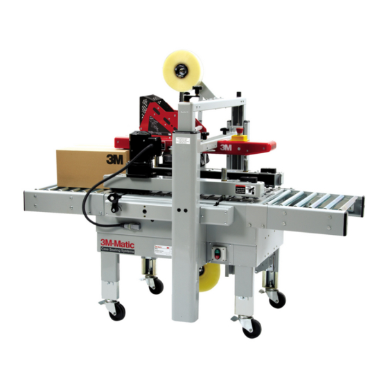
Description The 3M-Matic 800asb Adjustable Case Sealer with AccuGlide 1-1/2 Inch Taping Heads is designed to apply a “C” clip of Scotch brand pressure-sensitive film box sealing tape to the top and bottom center seam of regular slotted containers. The case sealer is manually adjustable to a wide range of box sizes (see Box Weight and Size Capacities, page 8). -
Page 8: Equipment Warranty And Limited Remedy
3M is notified of the problem no later than five (5) calendar days after the warranty period. If 3M is unable to repair or replace the part within a reasonable time, then 3M, at its option, will replace the equipment or refund the purchase price. -
Page 9: Important Safeguards
Important Safeguards The "Warning – Hazardous Voltage" label, shown This safety alert symbol identifies in Figure 1-2, is attached to the cover of the important messages in this manual. electrical control box. The label warns service READ AND UNDERSTAND THEM BEFORE personnel to unplug the power supply before INSTALLING OR OPERATING THIS attempting any service work on the case sealer. - Page 10 Important Safeguards (Continued) An emergency stop switch is located on the left, The "Caution – Pinch Point" label, shown in infeed side of the machine. The "Stop" label, Figure 1-4, is attached to the upper assembly shown in Figure 1-6, is located in front of the switch crossbar next to each of the compression roller and reminds operators and casual personnel of the locking knobs.
- Page 11 Important Safeguards (Continued) The "Operating Notice" label, shown in The "Up/Down/Lock" label shown in Figure 1-9, is Figure 1-8, is located on the top, infeed end of both located on the top surface, on each side of the upper drive belt assemblies. The labels remind operators column assembly.
- Page 12 THIS PAGE IS BLANK...
-
Page 13: Specifications
36 mm [1.5 in] The machine is equipped with an 2.4 m [8 ft] standard neoprene covered power cord and a grounded plug. Contact your 3M Representative for power requirements not listed above. 6. Tape Roll Diameter: 2. Operating Rate: Up to 405 mm [16 in] maximum on a 76.2 mm... - Page 14 Specifications (Continued) 9. Box Weight and Size Capacities: Weight Note: The case sealer is designed to Maximum – up to 38.6 kg [85 lbs] accommodate most boxes complying with the 1976 Minimum – contents must support top flaps and FBA and PMMI*** voluntary standard "Tolerances weight must be sufficient to hold bottom flaps for Top Opening"...
- Page 15 Specifications (Continued) Machine Dimensions: Minimum mm [Inches] 980 [38.50] 920 [36.25] 1335 [52.50] 460 [18] 610 [24] * 105 [4.18] 620 [24.50] Maximum mm [Inches] 2184 [86] * 890 [35] * * With outer columns relocated to upper position, "H" maximum dimension increases 100 mm [4 in] and "B"...
- Page 16 THIS PAGE IS BLANK...
-
Page 17: Installation And Set-Up
If damage is evident, file a damage claim immediately with the transportation company PACKAGING AND SEPARATE PARTS and also notify your 3M Representative. STEPS 1 THRU 5 Machine Set-Up 1. Lift fiberboard cover off pallet after removing staples at bottom. -
Page 18: Tape Drum Bracket
Installation and Set-Up (Continued) d. Plug each motor cord into receptacle on 3. Install the crank handle on the top of the left each side of case sealer bed and secure column, as shown in Figure 2-1A. with receptacle clamp. 4. -
Page 19: Tape Leg Length
Installation and Set-Up (Continued) Figure 2-3 – Machine Bed Height Adjustment and Lower Tape Drum Bracket Position plugged into 115 Volt, 60 Hz outlet, make sure TAPE LEG LENGTH that all packaging materials and tools are Taping heads are pre-set to apply 50 mm [2 in] removed from the machine. - Page 20 THIS PAGE IS BLANK...
-
Page 21: Operation
Operation IMPORTANT – Before operating the case sealer read all the "Important Safeguards", pages 3-5 and "Warnings", on page 16 as well as all of the "Operation" instructions. Refer to Figure 3-1 to acquaint yourself with the various components of the case sealer and also see Section II, page 6, for taping head components. -
Page 22: Operation "Warnings
Operation (Continued) WARNINGS 1. Turn electrical supply off and disconnect before servicing taping heads or performing any adjustments or maintenance on the machine. 2. Turn electrical supply off when machine is not in use. 3. Before turning drive belts on, be sure no tools or other objects are on the machine bed. 4. -
Page 23: Box Size Set-Up
Operation (Continued) Box Size Set-Up 1. ADJUST DRIVE BELTS (Figure 3-2) Place a product filled box on infeed conveyor bed with top flaps folded as shown and manually move box forward to contact lower taping head applying roller. Turn drive belt adjustment crank to position both side drive belts against sides of box. - Page 24 Operation (Continued) 3. POSITION COMPRESSION ROLLERS (Figure 3-4) The top flap compression rollers have an adjustable slide mounting to provide side compression on boxes higher than 110 mm [4.25 in]. Manually move box forward so front of box is aligned with top flap compression rollers. Adjust the compression rollers against top edge of box and tighten knobs to secure rollers in operating position.
-
Page 25: Box Sealing
Operation (Continued) Box Sealing 1. Feed boxes to machine at minimum 455 mm [18 in] intervals. 2. Turn electrical supply "Off" when machine is not in use. 3. Reload and thread tape as necessary. 4. Be sure machine is cleaned and lubricated according to recommendations in "Maintenance"... - Page 26 THIS PAGE IS BLANK...
-
Page 27: Maintenance
Maintenance Figure 4-1 illustrates the frame points which should The case sealer has been designed for long, be lubricated every 250 hours of operation. trouble-free service. The machine will perform best Lubricate the rotating and pivoting points, noted by when it receives routine maintenance and cleaning. the arrows, ( ) with SAE #30 non-detergent oil. -
Page 28: Circuit Breaker
2.2 amps and Drive Belts requires no further maintenance. Note – 3M recommends the replacement of WARNING – The following drive belts in pairs, especially if belts are procedure must be performed by unevenly worn. - Page 29 Maintenance (Continued) Figure 4-3 – Box Drive Assembly, Infeed End 4. Turn belt adjustment screws (G) 7. To set drive belt tension, turn adjustment screws counterclockwise on both the upper and lower (G) equally on both the upper and lower tension tension assemblies until belt is loose.
- Page 30 THIS PAGE IS BLANK...
-
Page 31: Adjustments
Adjustments WARNING – Turn off electrical power supply and disconnect power cord from electrical supply before beginning adjustments. If power cord is not disconnected, severe injury to personnel could result. Drive Belt Tension Tension adjustment of the drive belts may be required during normal operation. Belt tension must be adequate to positively move the box through the machine and they should run fully on the surface of the pulleys at each end of the frame. - Page 32 THIS PAGE IS BLANK...
-
Page 33: Special Set-Up Procedure
Special Set-Up Procedure WARNING – Turn off electrical power and disconnect power cord from electrical supply before beginning special set-up procedure, if power cord is not disconnected, severe injury to personnel could result. Drive Belt Height The drive belt assemblies can be raised 55 mm [2.16 in] to provide better conveying of tall boxes. -
Page 34: Changing Tape Leg Length
Special Set-Up Procedure (Continued) Box Height Range WARNING – Turn off electrical power (Outer Column – Re-Positioning) and disconnect power cord from electrical supply before beginning special WARNING – It is recommended that set-up procedure, if power cord is not no less than two people assist on this disconnected, severe injury to personnel set-up or severe injury or equipment... - Page 35 Special Set-Up Procedure (Continued) Figure 5-3 – Upper Frame Removal...
- Page 36 Special Set-Up Procedure (Continued) 8. If necessary, slip width adjustment crank on WARNING – Turn off electrical power shaft and rotate until chain master link is in and disconnect power cord from convenient position for removal. electrical supply before beginning special set-up procedure, if power cord is not disconnected, severe injury to personnel Important –...
- Page 37 Special Set-Up Procedure (Continued) 11. Reverse procedure, Steps 1-9 to reassemble WARNING – Turn off electrical power machine. and disconnect power cord from electrical supply before beginning special set-up procedure, if power cord is not Note – When installing upper assembly disconnected, severe injury to personnel back into machine (removed in Step 3), slide could result.
- Page 38 THIS PAGE IS BLANK...
-
Page 39: Troubleshooting
Troubleshooting The Troubleshooting Guide lists some possible machine problems, causes and corrections. Also see Section II "Troubleshooting", pages 15 and 16 for taping head problems. Troubleshooting Guide Problem Cause Correction Drive belts do not convey boxes Narrow boxes Check machine specifications. Boxes are narrower than recommended, causing slippage and premature belt wear. -
Page 40: Electrical Diagram
Electrical Diagram WARNING – Turn off electrical power supply and disconnect power cord from electrical supply before beginning service. If power cord is not disconnected, personnel could be exposed to dangerous voltages. Severe injury or equipment damage could result. Figure 6 – Electrical Diagram... -
Page 41: Spare Parts/Tools
The threading tool, part number 78-8076-4726-4, contained in the tool kit is available as a stock replacement item and can be ordered separately. Options/Accessories For additional information on the options/accessories listed below, contact your 3M Representative. Part Number Option/Accessory... -
Page 42: Replacement Parts Illustrations And Parts Lists
4. Refer to the first page of this instruction manual for replacement parts ordering information. IMPORTANT – Not all the parts listed are normally stocked items. Some parts or assemblies shown are available only on a special order basis. Contact 3M/Tape Dispenser Parts to confirm item availability. - Page 43 ™ 800asb Adjustable Case Sealer W/AccuGlide STD 1-1/2 Inch Taping Heads 800asb Assembly...
- Page 44 800asb Adjustable Case Sealer Figure 2799...
- Page 45 Figure 2799 Ref. No. 3M Part No. Description 2799-1 78-8070-1564-5 Tape Drum Bracket Assembly 2799-2 78-8070-1565-2 Tape Drum Bracket Assembly 2799-3 78-8070-1566-0 Bracket – Tape Drum 2799-4 78-8070-1395-4 Bracket – Bushing Assembly 2799-5 78-8070-1568-6 Cap – Bracket 2799-6 78-8076-4519-3 Shaft – Tape Drum...
- Page 46 800asb Adjustable Case Sealer Figure 4790...
- Page 47 Figure 4790 Ref. No. 3M Part No. Description 4790-1 78-8094-6128-4 Cross Bar 4790-2 26-1003-7957-2 Screw – Soc Hd Hex Hd, M6 x 16 4790-3 78-8100-1042-7 Washer – /15 x 6.35 x 2 4790-4 78-8100-1233-2 Top Head Assembly – 1-1/2 Inch Wide...
- Page 48 800asb Adjustable Case Sealer Figure 4792...
- Page 49 Figure 4792 Ref. No. 3M Part No. Description 4792-1 78-8070-1206-3 Arm – Applying, R/H 4792-2 78-8070-1207-1 Arm – Applying, L/H 4792-3 78-8094-6146-6 Plate 4792-4 78-8094-6147-4 Shaft – /10 4792-5 78-8094-6148-2 Roller – Knurled 4792-6 78-8094-6149-0 Roller 4792-7 78-8094-6150-8 Spacer – Hex...
- Page 50 800asb Adjustable Case Sealer Figure 4793...
- Page 51 Figure 4793 Ref. No. 3M Part No. Description 4793-1 78-8094-6484-1 Arm – Buffing, R/H 4793-2 78-8094-6485-8 Arm – Buffing, L/H 4793-3 78-8094-6152-4 Shaft – /10 x 48 4793-4 78-8094-6154-0 Bushing – Buffing Roller 4793-5 78-8094-6155-7 Roller – Buffing 4793-7 78-8094-6156-5 Spacer –...
- Page 52 800asb Adjustable Case Sealer Figure 4794...
- Page 53 Figure 4794 Ref. No. 3M Part No. Description 4794-1 78-8070-1388-9 Link – Arm Bushing Assembly 4794-2 78-8070-1389-7 Link – Arm Bushing Assembly 4794-3 78-8094-6158-1 Shaft – Pivot 4794-4 78-8094-6151-6 Washer 4794-5 78-8017-9082-1 Bearing – Special, 30 mm 4794-6 78-8017-9106-8 Screw – Bearing Shoulder...
- Page 54 800asb Adjustable Case Sealer Figure 4795...
- Page 55 Figure 4795 Ref. No. 3M Part No. Description 4795-1 78-8094-6159-9 Frame – Cut-Off Weldment 4795-2 78-8017-9173-8 Knife – 2.56 Inches (65 mm) 4795-3 26-1002-5817-2 Screw – Hex Hd, M5 x 8 4795-4 78-8113-6821-2 Knife Guard Assembly – W/English Label 4795-5 78-8094-6161-5 Shaft –...
- Page 56 800asb Adjustable Case Sealer Figure 4796...
- Page 57 Figure 4796 Ref. No. 3M Part No. Description 4796-1 78-8094-6163-1 Roller Assembly – R/H 4796-2 78-8094-6164-9 Roller Assembly – L/H 4796-3 78-8070-1559-5 Support – Compression Roller 4796-4 78-8054-8974-3 Pressure Roller 4796-5 78-8094-6165-6 Shaft – Roller 4796-6 78-8052-6566-3 Washer – Friction...
- Page 58 800asb Adjustable Case Sealer Figure 5213...
- Page 59 Figure 5213 Ref. No. 3M Part No. Description 5213-1 78-8060-8489-9 Column – Outer 5213-2 78-8076-5426-0 Plate 5213-3 26-1003-7964-8 Screw – Soc Hd, M8 x 20 5213-4 78-8017-9318-9 Washer – Plain 8 mm 5213-5 78-8060-8491-5 Cap – Column 5213-6 26-1002-4955-1 Screw – Self-Tap, 8P x 13...
- Page 60 800asb Adjustable Case Sealer Figure 5213...
- Page 61 Figure 5285 Ref. No. 3M Part No. Description 5285-1 78-8076-4636-5 Strap – Wire 5285-2 78-8010-7163-6 Screw – Hex Hd, M5 x 10 5285-3 78-8005-5741-1 Washer – Flat, M5 5285-4 78-8046-8217-3 Washer – Special 5285-5 78-8010-7417-6 Nut – Hex Stl, M5...
- Page 62 800asb Adjustable Case Sealer Figure 6177...
- Page 63 Figure 6177 Ref. No. 3M Part No. Description 6177-1 78-8094-6379-3 Support – Box 6177-2 78-8094-6380-1 6177-3 78-8094-6381-9 Screw – Soc Hd, Hex Hd, M4 x 15 6177-4 78-8005-5740-3 Washer – Plain, 4 mm 6177-5 26-1003-6914-4 Nut – Plastic Insert, M4...
- Page 64 800asb Adjustable Case Sealer Figure 6183/1 of 2...
- Page 65 Figure 6183 (page 1 of 2) Ref. No. 3M Part No. Description 6183-1 78-8113-6805-5 Machine Bed Assembly – W/English Language Label 6183-2 78-8076-5381-7 Leg Assembly – Inner, W/Stop 6183-3 78-8076-5382-5 Leg – Inner 6183-4 78-8060-8480-8 Pad – Foot 6183-5 78-8055-0867-4 Screw –...
- Page 66 800asb Adjustable Case Sealer Figure 6183/2 of 2...
- Page 67 Figure 6183 (page 2 of 2) Ref. No. 3M Part No. Description 6183-29 78-8032-0375-7 Screw – Hex Hd, M6 x 16 6183-30 26-1000-0010-3 Washer – Flat M6 6183-31 26-1003-7957-2 Screw – Soc Hd Hex Hd, M6 x 16 6183-32 78-8060-8487-3 Cover –...
- Page 68 800asb Adjustable Case Sealer Figure 6184/1 of 2...
- Page 69 Figure 6184 (page 1 of 2) Ref. No. 3M Part No. Description 6184-1 78-8100-1229-0 Shaft Assembly – Drive, R/H 6184-2 78-8100-1230-8 Shaft Assembly – Drive, L/H 6184-3 78-8076-5401-3 Block – Upper 6184-4 78-8076-5402-1 Block – Lower 6184-5 78-8076-5403-9 Nut – Block, R/H...
- Page 70 800asb Adjustable Case Sealer Figure 6184/2 of 2...
- Page 71 Figure 6184 (page 2 of 2) Ref. No. 3M Part No. Description 6184-28 78-8017-9079-7 Ring – Snap For 15 mm Shaft 6184-29 78-8076-5418-7 Support – Screw 6184-30 26-1003-7949-9 Screw – Soc Hd Hex Soc, M5 x 12 6184-31 78-8005-5741-1 Washer – Plain M5...
- Page 72 800asb Adjustable Case Sealer Figure 6185/1 of 2...
- Page 73 Figure 6185 (page 1 of 2) Ref. No. 3M Part No. Description 6185-1 78-8100-1205-0 Drive Assembly – R/H, W/O Motor 6185-2 78-8100-1206-8 Drive Assembly – L/H, W/O Motor 6185-3 78-8100-1207-6 Guide – Lower, R/H 6185-4 78-8100-1208-4 Guide – Lower, L/H...
- Page 74 800asb Adjustable Case Sealer Figure 6185/2 of 2...
- Page 75 Figure 6185 (page 2 of 2) Ref. No. 3M Part No. Description 6185-35 78-8076-5443-5 Pulley Assembly – Idler 6185-36 78-8055-0660-3 Roller – Idler 6185-37 78-8076-5444-3 Shaft – Idler Pulley 6185-38 12-7997-0272-0 E-Ring – M-25 6185-39 78-8076-5445-0 Tensioning – Belt 6185-40 78-8076-5446-8 Washer –...
- Page 76 800asb Adjustable Case Sealer Figure 6186...
- Page 77 Figure 6186 Ref. No. 3M Part No. Description 6186-1 78-8113-6820-4 Frame Assembly – Top, R/H, W/English Language Label 6186-2 78-8113-6808-9 Frame Assembly – Top, L/H, W/English Language Label 6186-3 78-8068-4143-9 Guide – #1 6186-4 78-8068-4144-7 Guide – #2 6186-5 83-0002-7336-3 Screw –...
- Page 78 800asb Adjustable Case Sealer Safety and Information Labels...
- Page 79 78-8098-8966-6 Label Kit (Includes items 1 - 18) 78-8070-1366-5 Information – Safety Instructions 78-8070-1628-8 Information – Up/Down/Lock, Height Adjustment 78-8070-1339-2 Information – 3M Logo 78-8098-8818-9 Information – Box Centering 78-8068-3859-1 Information – Service and Spares 78-8070-1331-9 Warning – Moving Belts 78-8070-1329-3 Warning –...
- Page 80 THIS PAGE INTENTIONALLY LEFT BLANK...