Table of Contents
Advertisement
Instructions and Parts List
3M-Matic
700a
Adjustable
Case Sealer
with
AccuGlide
Taping Heads
Serial No.
For reference, record machine serial number here.
3M Packaging Systems Division
3M Center, Building 220-8W-01
St. Paul, MN 55144-1000
TM
Type 39600
TM
II
Important Safety
Information
Read "Important Safeguards",
pages 3-5 and also
operating "Warnings",
page 14 BEFORE
INSTALLING OR
OPERATING THIS
EQUIPMENT.
Spare Parts
It is recommended you
immediately order the spare
parts listed on page 31,
Section I and page 17,
Section II. These parts are
expected to wear through
normal use and should be
kept on hand to minimize
production delays.
"3M-Matic"and "AccuGlide" are Trademarks
of 3M, St. Paul, MN 55144-1000
Litho in U.S.A.
© 3M 1999 44-0009-1906-6 (D59.0)
Advertisement
Table of Contents

Related Manuals for 3M 3M-Matic 700a


Summary of Contents for 3M 3M-Matic 700a
- Page 1 Serial No. For reference, record machine serial number here. "3M-Matic"and "AccuGlide" are Trademarks 3M Packaging Systems Division of 3M, St. Paul, MN 55144-1000 Litho in U.S.A. 3M Center, Building 220-8W-01 St. Paul, MN 55144-1000 © 3M 1999 44-0009-1906-6 (D59.0)
- Page 2 Minimum billing on parts orders will be $25.00. Replacement part prices available on request. $10.00 restocking charge per invoice on returned parts. Note : Outside the U.S., contact the local 3M subsidiary for parts ordering information. "3M-Matic", "AccuGlide" and “Scotch” are trademarks of 3M Packaging Systems Division 3M, St.
- Page 3 Replacement Parts And Service Information To Our Customers: This is the 3M-Matic™/AccuGlide™/Scotch™ brand equipment you ordered. It has been set up and tested in the factory with "Scotch" brand tapes. If any problems occur when operating this equipment, and you desire a service call, or phone consultation, call, write or Fax the appropriate number listed below.
-
Page 4: Table Of Contents
Instruction Manual 700a, Adjustable Case Sealer, Type 39600 This instruction manual is divided into two sections as follows: Section Includes all information related to installation, operation and parts for the case sealer. Section Includes specific information regarding the AccuGlide™ STD 2 Inch Taping Heads. Table of Contents Page Section... - Page 5 Table of Contents (Continued) Page Maintenance ............................18 - 20 Cleaning ....................... Lubrication ......................Box Drive Belt Replacement ................Circuit Breaker ..................... Blade Replacement, Taping Head ............... Adjustments ............................. 21 - 23 Box Drive Belt Tension ..................21 - 22 Taping Head Adjustments ..................
-
Page 6: Description
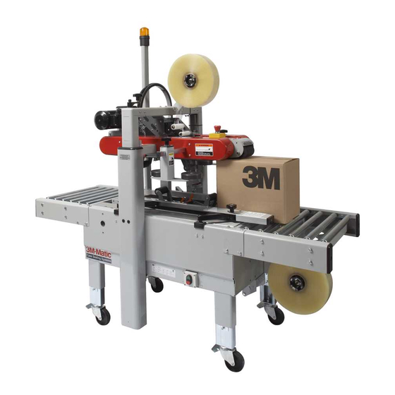
Description The 3M-Matic 700a Adjustable Case Sealer with AccuGlide II Taping Heads is designed to apply a “C” clip of Scotch brand pressure-sensitive film box sealing tape to the top and bottom center seam of regular slotted containers. The 700a is manually adjustable to a wide range of box sizes (see "Specifications – Box Weight and Size Capacities", Page 7). -
Page 7: Equipment Warranty And Limited Remedy
3M’s factory or an authorized service station designated by 3M. A part will be presumed to have become defective after its warranty period unless the part is received or 3M is notified of the problem no later than five (5) calendar days after the warranty period. -
Page 8: Important Safeguards
Important Safeguards The "Warning – Hazardous Voltage" label, shown This safety alert symbol identifies in Figure 1-2, is attached to the cover of the important messages in this manual. electrical enclosure. The label warns service READ AND UNDERSTAND THEM BEFORE personnel to unplug the power supply before INSTALLING OR OPERATING THIS attempting any service work on the case sealer. - Page 9 Important Safeguards (Continued) The "Caution – Pinch Point" label, shown in The 700a is equipped with a "Red" emergency stop Figure 1-4, is attached to the center plate at the exit switch located on the top/front of the upper ski end of the machine bed.
-
Page 10: Important Safeguards
Important Safeguards (Continued) The "Notice – Taping Head Latch" label, shown in Figure 1-10 is attached to the top surface of the upper, left belt guard at the front edge of the taping The "Center Box Here" label, shown in Figure 1-8, head. -
Page 11: Specifications
Electrical - 115 VAC, 60 Hz, 3.8 A (440 watts) The machine is equipped with a 2.4 m [8 foot] standard neoprene covered power cord and a grounded plug. Contact your 3M Representative for power requirements not listed above. 2. Operating Rate: Box drive belt speed is approximately 0.4 m/s [78 feet per minute]. - Page 12 (See "Special Set-Up Procedure – Box and Machine Bed Height Range", Page 26.) Special modifications may be available for carton sizes not listed above. Contact your 3M Representative for information. Note: The case sealer can accommodate most boxes within the size range listed above. However, if the box length (in direction of seal) to box height ratio is .5 or less, then several boxes should be test run...
-
Page 13: Specifications
Specifications (Continued) 10. Machine Dimensions: Minimum 1030 1350 [Inches] [31] [40 .5] [53] [18] [24]*** [24.5] Maximum 2185 [Inches] [86]*** [35]*** * Infeed/Exit conveyors are optional ** Casters are optional *** When columns are adjusted to upper position, "B" minimum dimension is 520 mm [20.5 inch], maximum dimension is 780 mm [31 inch] and "H"... -
Page 14: Installation And Set-Up
If damage is evident, file a damage claim immediately with the transportation company Install height adjustment crank and locking and also notify your 3M Representative. knob on top of left column as shown in Figure 2-1B. Crank upper assembly up high enough to allow clear access to lower taping head. - Page 15 Installation and Set-Up (Continued) Figure 2-1 – 700a Frame Set-Up 14. Use appropriate material handling equipment 11. Check for free action of both upper and lower to remove the machine from the pallet and taping heads. move it into position. WARNING –...
-
Page 16: Machine Bed Height
Installation and Set-Up (Continued) MACHINE BED HEIGHT Adjust machine bed height. The case sealer is 2. Loosen, but do not remove, two M8 x 1.25 equipped with four adjustable legs that are socket head screws in one leg (use M6 hex located at the corners of the machine frame. -
Page 17: Box Size Capacity Of Case Sealer
Installation and Set-Up (Continued) BOX SIZE CAPACITY OF CASE SEALER Use of an extension cord is not recommended. At its factory setting, the case sealer handles However, if one is needed for temporary use, it box sizes up to 620 mm [24.5 inch] maximum must have a wire size of 1.5 mm diameter height. -
Page 18: Operation
Operation IMPORTANT – Before operating the case sealer, read the "Safety Labels", pages 3-5 and "Warnings" on page 14 as well as all of the "Operation" instructions. Refer to Figure 3-1 below to acquaint yourself with the various components and controls of the case sealer. Also see Figures 3-1 and 3-2 in Section II for taping head components. -
Page 19: Electrical On/Off Switch
Operation (Continued) WARNINGS 1. Turn electrical supply off and disconnect before servicing taping heads or performing any adjustments or maintenance on the machine. 2. Do not leave machine running unattended. 3. Before turning drive belts on, be sure no tools or other objects are on the machine bed. 4. -
Page 20: Box Size Set-Up
Operation (Continued) Box Size Set-Up 1. ADJUST UPPER TAPING HEAD The upper taping head is positioned for the box height by means of the height adjustment crank shown in Figure 3-2. Turn crank clockwise to lower head, counterclockwise to raise head. Move the top flap compression rollers to a position wider than the box. -
Page 21: Run Boxes To Check Adjustment
Operation (Continued) 3. RUN BOXES TO CHECK ADJUSTMENT (Figure 3-5) Turn electrical switch to "On" to start drive belts. Move box forward under upper taping head until it is taken away by drive belts. If box is hard to move under head or is crushed, raise head slightly. -
Page 22: Box Sealing
Operation (Continued) Box Sealing 1. Feed boxes to machine at minimum 455 mm [18 inch] intervals. 2. Turn electrical supply "Off" when machine is not in use. 3. Reload and thread tape as necessary. 4. Be sure machine is cleaned and lubricated according to recommendations in "Maintenance"... -
Page 23: Maintenance
Maintenance The case sealer has been designed for long, trouble Lubrication free service. The machine will perform best when it receives routine maintenance and cleaning. Most of the machine bearings, including the drive Machine components that fail or wear excessively motor, are permanently lubricated and sealed and should be promptly repaired or replaced to prevent do not require additional lubricant. -
Page 24: Box Drive Belt Replacement
If power cord is not disconnected, severe injury to personnel could result. Box Drive Belt Replacement Note – 3M recommends the replacement of drive belts in pairs, especially if belts are unevenly worn. LOWER DRIVE BELTS Figure 4-2 1. -
Page 25: Circuit Breaker
Maintenance (Continued) WARNING – Turn off electrical power supply and disconnect power cord from electrical supply before beginning maintenance. If power cord is not disconnected, severe injury to personnel could result. Circuit Breaker Blade Replacement, Taping Head The case sealer is equipped with a circuit breaker See Section II, "Maintenance –... -
Page 26: Adjustments
Adjustments WARNING – Turn off electrical power supply and disconnect power cord from electrical supply before beginning adjustments. If power cord is not disconnected, severe injury to personnel could result. Box Drive Belt Tension The four continuously moving drive belts convey boxes through the tape applying mechanism. The box drive belts are powered by an electric gear motor. - Page 27 Adjustments (Continued) WARNING – Turn off electrical power supply and disconnect power cord from electrical supply before beginning adjustments. If power cord is not disconnected, severe injury to personnel could result. Refer to Figure 5-2 and 5-3 and adjust belt tension as follows: 1.
-
Page 28: Taping Head Adjustments
Adjustments (Continued) WARNING – Turn off electrical power supply and disconnect power cord from electrical supply before beginning adjustments. If power cord is not disconnected, severe injury to personnel could result. Figure 5-3 – Box Drive Belt Tension Adjustment, Upper Belts (Infeed End) Taping Head Adjustments –... - Page 29 THIS PAGE IS BLANK...
-
Page 30: Special Set-Up Procedure
Special Set-Up Procedure WARNING – Turn off electrical power and disconnect power cord from electrical supply before beginning Special Set-Up Procedure. If power cord is not disconnected, severe injury to personnel could result. Changing the Tape Leg Length (From 70 to 50 mm [2-3/4 to 2 inch]) The following changes to the case sealer frame and upper/lower taping heads will allow the taping of boxes 90 mm [3.5 inch] minimum height. - Page 31 Special Set-Up Procedure (Continued) WARNING – Turn off electrical power and disconnect power cord from electrical supply before beginning Special Set-Up Procedure. If power cord is not disconnected, severe injury to personnel could result. TAPING HEADS WARNING – Use care when working near blades as blades are extremely sharp. If care is not taken, severe injury to personnel could result.
-
Page 32: Box And Machine Bed Height Range
Special Set-Up Procedure (Continued) Box and Machine Bed Height Range – Refer to Figure 6-4 Moving the outer columns up one set of mounting holed increases the maximum box size handled by the 700a case sealer and decreases the minimum machine bed height. Note –... -
Page 33: Troubleshooting
Troubleshooting The Troubleshooting Guide lists some possible machine problems, causes and corrections. Also see Section II "Troubleshooting", pages 15 and 16 for taping head problems. Troubleshooting Guide Problem Cause Correction Drive belts do not convey boxes Narrow boxes Check machine specifications. Boxes are narrower than recommended, causing slippage and premature belt wear. -
Page 34: Electrical Diagram
Electrical Diagram WARNING – Turn off electrical power and disconnect power cord from electrical supply before beginning service. If power cord is not disconnected, personnel could be exposed to dangerous voltages that could cause severe injury or equipment damage. Figure 7-1 – Electrical Diagram... - Page 35 THIS PAGE IS BLANK...
-
Page 36: Parts And Service Information
Replacement Parts And Service Information Spare Parts It is suggested that the following spare parts be ordered and kept on hand: Qty. Ref. No. Part Number Description 5667-43 & 5668-59 78-8070-1531-4 Belt - Drive W/Pin Also see Section II, page 17 for recommended taping head spare parts. Label Kit In the event that any labels are damaged or destroyed, they must be replaced to ensure operator safety. -
Page 37: Options/Accessories
Options/Accessories For additional information on the options/accessories listed below, contact your 3M Representative. Part Number Option/Accessory 78-8052-6553-1 Box Hold Down Attachment, Model 18500 78-8069-3983-7 Caster Kit Attachment 78-8069-3924-1 Conveyor Extension Attachment 78-8069-3926-6 Low Tape Sensor Kit 78-8114-0828-1 AccuGlide II STD 2 Inch Upper Taping Head, Type 39600... -
Page 38: Replacement Parts Illustrations And Parts Lists
Refer to the first page of this instruction manual “Replacement Parts and Service Information” for replacement parts ordering information. IMPORTANT – Not all the parts listed are normally stocked items. Some parts or assemblies shown are available only on special order. Contact 3M/Tape Dispenser Parts to confirm item availability. - Page 39 THIS PAGE IS BLANK...
- Page 40 700a Adjustable Case Sealer Frame Assemblies...
- Page 41 700a Adjustable Case Sealer Figure 2796...
- Page 42 Figure 2796 Ref. No. 3M Part No. Description 2796-1 78-8070-1536-3 Support – Guide Arm 2796-2 78-8010-7169-3 Screw – Hex Hd, M6 x 12 2796-3 26-1000-0010-3 Washer – Flat, M6 2796-4 78-8070-1537-1 Lever With Pivot 2796-5 78-8070-1538-9 Bushing 2796-6 26-1003-8816-9 Screw – Set, M5 x 6...
- Page 43 700a Adjustable Case Sealer Figure 2806...
- Page 44 Figure 2806 Ref. No. 3M Part No. Description 2806-1 78-8076-4626-6 Compression Roller Assembly 2806-2 78-8076-4627-4 Support – Compression Roller 2806-3 78-8076-4628-2 Roller – Compression 2806-4 78-8076-4629-0 Shaft – Roller 2806-5 26-1003-5841-0 Screw – M8 x 16 2806-6 78-8017-9318-9 Washer – Plain 8 mm...
- Page 45 700a Adjustable Case Sealer Figure 2807...
- Page 46 Figure 2807 Ref. No. 3M Part No. Description 2807-1 78-8076-4633-2 Tape Roll Bracket Assembly 2807-2 78-8070-1565-2 Tape Drum Bracket Assembly 2807-3 78-8070-1566-0 Bracket – Tape Drum 2807-4 78-8070-1395-4 Bracket – Bushing Assembly 2807-5 78-8070-1568-6 Cap – Bracket 2807-6 78-8076-4519-3 Shaft – Tape Drum...
- Page 47 700a Adjustable Case Sealer Figure 3433...
- Page 48 Figure 3433 Ref. No. 3M Part No. Description 3433-1 78-8091-0309-2 Conveyor Bed Assembly 3433-2 78-8091-0310-0 Bed – Conveyor 3433-3 78-8091-0307-6 Support – Drive 3433-4 26-1003-5842-8 Screw – Hex Hd M8 x 20 3433-5 78-8017-9318-9 Washer – Plain 8 mm 3433-6 78-8076-5381-7 Leg Assembly –...
- Page 49 700a Adjustable Case Sealer Figure 3434...
- Page 50 Figure 3434 Ref. No. 3M Part No. Description 3434-1 78-8060-8489-9 Column – Outer 3434-2 78-8060-8490-7 Plate – Column Mounting 3434-3 26-1003-7964-8 Screw – Soc Hd Hex Soc Dr, M8 x 20 3434-4 78-8017-9318-9 Washer – Plain 8 mm 3434-5 78-8060-8491-5 Cap –...
- Page 51 700a Adjustable Case Sealer Figure 5667/1 of 2...
- Page 52 Figure 5667 (Page 1 of 2) Ref. No. 3M Part No. Description 5667-1 78-8100-1128-4 Drive Assembly – BTM, W /O Motor 5667-2 78-8070-1580-1 Frame – Drive 5667-3 78-8070-1514-0 Spacer 5667-4 26-1003-5829-5 Screw – Hex Hd, M6 x 12 5667-7 78-8052-6710-7 Roller –...
- Page 53 700a Adjustable Case Sealer Figure 5667/2 of 2...
- Page 54 Figure 5667 (Page 2 of 2) Ref. No. 3M Part No. Description 5667-28 78-8076-4562-3 Cover – Bottom 5667-29 26-1003-5820-4 Screw – Hex Hd, M5 x 12 5667-30 78-8005-5741-1 Washer – Flat, M5 5667-31 78-8070-1527-2 Shaft – With Drive Pulleys 5667-32 78-8070-1528-0 Shaft –...
- Page 55 700a Adjustable Case Sealer Figure 5668/1 of 2...
- Page 56 Figure 5668 (Page 1 of 2) Ref. No. 3M Part No. Description 5668-1 78-8100-1129-2 Upper Drive Assembly – W /O Motor 5668-2 78-8070-1588-4 Frame – Drive, Upper 5668-3 78-8070-1520-7 Guide – Drive Belt 5668-4 26-1005-4757-4 Screw – Flat Hd M5 x 20...
- Page 57 700a Adjustable Case Sealer Figure 5668/2 of 2...
- Page 58 Figure 5668 (Page 2 of 2) Ref. No. 3M Part No. Description 5668-35 78-8057-5811-3 Key – 6 x 6 x 20 mm 5668-36 78-8054-8986-7 Sprocket – 3/8" Pitch 28 Teeth 5668-37 78-8054-8984-2 Bushing 5668-38 78-8070-1529-8 Support – Shaft 5668-39 78-8070-1530-6 Bearing –...
- Page 59 700a Adjustable Case Sealer Figure 5669...
- Page 60 Figure 5669 Ref. No. 3M Part No. Description 5669-1 78-8091-0660-8 Housing – Wire 5669-2 78-8076-4702-5 Grommet – /28 5669-3 26-1003-7963-0 Screw – Soc Hd M8 x 16 5669-4 78-8076-4636-5 Strap – Wire 5669-5 78-8010-7163-6 Screw – Hex Hd M5 x 10...
- Page 61 700a Adjustable Case Sealer Figure 5670...
- Page 62 Figure 5670 Ref. No. 3M Part No. Description 5670-1 78-8094-6379-3 Support – Box 5670-2 78-8113-6759-4 Box – W/English Language Label 5670-3 78-8094-6381-9 Screw – Soc Hd, Hex Hd, M4 x 15 5670-4 78-8005-5740-3 Washer – Plain, 4 mm 5670-5 26-1003-6914-4 Nut –...
- Page 63 700a Adjustable Case Sealer Safety and Information Labels...
- Page 64 Description Qty. 78-8070-1318-6 Label – Box Centering 78-8070-1329-3 Label – Warning 78-8070-1336-8 Label – Warning 78-8070-1339-2 Information – 3M Logo 78-8069-3852-6 Label – Ground 78-8068-3859-1 Label – Service and Spares 78-8062-4266-1 Label – Product 78-8070-1628-8 Label – Up and Down/Lock 78-8070-1366-5 Label –...