Cisco Catalyst IW6300 Series Hardware Installation Manual
Heavy duty access point
Hide thumbs
Also See for Catalyst IW6300 Series:
- Getting started (20 pages) ,
- Installing manual (28 pages)
Table of Contents
Advertisement
Cisco Catalyst IW6300 Heavy Duty Series Access Point Hardware
Installation Guide
First Published: 2019-12-13
Last Modified: 2020-01-15
Americas Headquarters
Cisco Systems, Inc.
170 West Tasman Drive
San Jose, CA 95134-1706
USA
http://www.cisco.com
Tel: 408 526-4000
800 553-NETS (6387)
Fax: 408 527-0883
Advertisement
Chapters
Table of Contents

Related Manuals for Cisco Catalyst IW6300 Series


Summary of Contents for Cisco Catalyst IW6300 Series
-
Page 1: Installation Guide
Cisco Catalyst IW6300 Heavy Duty Series Access Point Hardware Installation Guide First Published: 2019-12-13 Last Modified: 2020-01-15 Americas Headquarters Cisco Systems, Inc. 170 West Tasman Drive San Jose, CA 95134-1706 http://www.cisco.com Tel: 408 526-4000 800 553-NETS (6387) Fax: 408 527-0883... -
Page 2: Table Of Contents
C H A P T E R 2 Before You Begin Unpacking the Access Point Package Contents Tools and Hardware Optional Tools and Hardware Optional Tools and Hardware That You Supply Cisco Catalyst IW6300 Heavy Duty Series Access Point Hardware Installation Guide... - Page 3 Connecting a Power Injector Connecting an Ethernet Cable to the Access Point Connecting AC Power to IW-6300H-AC-x-K9 Connecting DC Power to IW-6300H-DCW-x-K9 Connecting DC Power to IW-6300H-DC-x-K9 Performing Maintenance Cisco Catalyst IW6300 Heavy Duty Series Access Point Hardware Installation Guide...
- Page 4 Declaration of Conformity With Regard To The R&TTE Directive 1999/5/EC Declaration of Conformity for RF Exposure United States Canada European Union Australia Guidelines for Operating Cisco Catalyst Access Points in Japan Japanese Translation Cisco Catalyst IW6300 Heavy Duty Series Access Point Hardware Installation Guide...
- Page 5 A P P E N D I X B Access Point Specifications Technical Specifications Power Consumption Budget A P P E N D I X C Access Point Pinouts Access Point Pinouts Cisco Catalyst IW6300 Heavy Duty Series Access Point Hardware Installation Guide...
- Page 6 Contents Cisco Catalyst IW6300 Heavy Duty Series Access Point Hardware Installation Guide...
- Page 7 Cisco has more than 200 offices worldwide. Addresses and phone numbers are listed on the Cisco website at www.cisco.com/go/offices. Cisco and the Cisco logo are trademarks or registered trademarks of Cisco and/or its affiliates in the U.S. and other countries. To view a list of Cisco trademarks, go to this URL: www.cisco.com...
-
Page 9: Overview
C H A P T E R Overview This publication explains the steps for installing the Cisco Catalyst IW6300 Heavy Duty Series Access Point. • Audience , on page 1 • Conventions, on page 1 • About the Access Point, on page 2 •... -
Page 10: About The Access Point
Statement 1071 SAVE THESE INSTRUCTIONS About the Access Point Designed for the most hazardous industrial locations, Cisco Catalyst IW6300 Heavy Duty Access Points deliver wireless connectivity, IoT control, and robust data collection to dangerous environments. With 802.11ac Wave 2 connectivity, dual Power over Ethernet Plus (PoE+) out for IoT sensors or peripherals, multiple power-in sources, and a variety of uplink options, the IW6300 provides a flexible wireless solution. -
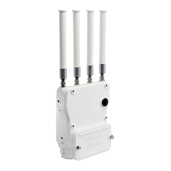
Page 11: Hardware Models
Hardware Models Figure 1: IW-6300H Access Points The model numbers (or part numbers) and configuration for the Cisco Catalyst IW6300 Heavy Duty Series Access Points are described in the following table. Table 1: Cisco Industrial Wireless 6300 Series Access Point Model Numbers and Descriptions... -
Page 12: Hardware Features
When powered with PoE+ or UPoE, the PoE Out power is not available, The PoE-Out port data link can still be active. Hardware Features This section describes the hardware features of the IW-6300H access point models. Cisco Catalyst IW6300 Heavy Duty Series Access Point Hardware Installation Guide... -
Page 13: Internal Connectors
Console Port and Reset Button The console port and reset button are under a covering M25 plug located on the side of the access point, as shown in the following figure. Cisco Catalyst IW6300 Heavy Duty Series Access Point Hardware Installation Guide... -
Page 14: Power Connector
The following figure shows the power connector of access point model IW-6300H-AC-x-K9. Figure 4: Power Connector of Access Point Model IW-6300H-AC-x K9 AC Power-IN Internal ground The following figure shows the power connector of access point model IW-6300H-DCW-x-K9. Cisco Catalyst IW6300 Heavy Duty Series Access Point Hardware Installation Guide... -
Page 15: Antenna Ports
Note Antenna caps must be installed when an antenna is not in use (maximum torque range: 6.2-9.7 in-lbs). Cisco Catalyst IW6300 Heavy Duty Series Access Point Hardware Installation Guide... - Page 16 When configured for single band antennas, antenna ports A and B support MIMO operation on the 2.4 GHz radio and antenna ports C and D support MIMO operation on the 5 GHz radio. See the Cisco Catalyst IW6300 Heavy Duty Series Access Point Software Configuration Guide.
-
Page 17: Power Sources
Output power is configurable in 3 dB steps. Its two receivers enable maximum-ratio combining (MRC). Power Sources The Cisco Catalyst IW6300 Heavy Duty Series Access Points support the following power options: • Power over Ethernet by power injector AIR-PWRINJ-60RGD1= and AIR-PWRINJ-60RGD2= • AC or DC power •... -
Page 18: Fiber Option
The four 1/2-NPT I/O ports are located at the bottom of the access point. These ports are tapered pipe threads. It is recommended that you use a 3/8” Allen wrench with 13-18" long wrench handle to remove the port plug. Cisco Catalyst IW6300 Heavy Duty Series Access Point Hardware Installation Guide... -
Page 19: Optional Hardware
(For example, Sealcon provides glands and adapters that are certified. See https://www.sealconex.com/?ex=9wkuir-fln65y-13897wy-drrs7y.) Optional Hardware Depending on the order configuration, the following optional access point hardware may be part of the shipment: • Cisco Aironet Antennas Cisco Catalyst IW6300 Heavy Duty Series Access Point Hardware Installation Guide... -
Page 20: Finding The Product Serial Number
You need your product serial number when requesting support from the Cisco Technical Assistance Center. Related Documentation To view all support information for the Cisco Catalyst IW6300 Heavy Duty Series Access Point, see: https://www.cisco.com/c/en/us/support/wireless/industrial-wireless-6300-series/tsd-products-support-series-home.html In addition to the documentation available on the support page, you will need to refer to the following guides: •... -
Page 21: Before You Begin
The typical access point package contains the following items: • Access point • IW-6300H-AC-x-K9 (AC power model) • IW-6300H-DC-x–K9 (DC power model) • IW-6300H-DCW-x-K9 (DC wide range power model) Cisco Catalyst IW6300 Heavy Duty Series Access Point Hardware Installation Guide... -
Page 22: Tools And Hardware
The tools and hardware used to install the access point are described in the following sections: Optional Tools and Hardware The optional tools and hardware that can be obtained from Cisco are: • Optional power injector (AIR-PWRINJ-60GRDx=) • Antennas, 2.4/5-GHz •... -
Page 23: Pole Installation Hardware And Tools
The FCC, with its action in ET Docket 96-8, has adopted a safety standard for human exposure to RF electromagnetic energy emitted by FCC-certified equipment. When used with approved Cisco Aironet antennas, Cisco Catalyst IW6300 Heavy Duty Series Access Point Hardware Installation Guide... -
Page 24: Safety Precautions
Before You Begin Safety Precautions Cisco Aironet products meet the uncontrolled environmental limits found in OET-65 and ANSI C95.1, 1991. Proper operation of this radio device according to the instructions in this publication results in user exposure substantially below the FCC recommended limits. -
Page 25: Avoiding Damage To Radios In A Testing Environment
At levels above the normal operating range, packet error rate (PER) performance is degraded. At even higher levels, the receiver can be permanently damaged. To avoid receiver damage and PER degradation, you can use one of the following techniques: Cisco Catalyst IW6300 Heavy Duty Series Access Point Hardware Installation Guide... -
Page 26: Safety Precautions When Installing Antennas
(e.g. U.S.: NFPA 70, National Electrical Code, Article 810, Canada: Canadian Electrical Code, Section 54). Statement 280 1. Before you install an antenna, contact your Cisco account representative to explain which mounting method to use for the size and type of antenna that you are about to install. -
Page 27: Installation Guidelines
• The access points can be installed at any height, but best throughput is achieved when all the access points are mounted at the same height. Cisco recommends installing the access points no higher than 40 feet to allow support for wireless clients on the ground. -
Page 28: Site Surveys
• Ensure that a DHCP server with Option 43 configured is reachable by your access points, or manually configure the controller information in the access point (for additional information, refer to the software configuration guide). • Become familiar with the access point installation components. Cisco Catalyst IW6300 Heavy Duty Series Access Point Hardware Installation Guide... -
Page 29: Installing The Access Point
All installation methods for mounting an access point on any wall surface is subject to the acceptance of local jurisdiction. Installation Option The Cisco Catalyst IW6300 Heavy Duty Series Access Points are installed using the pole mount installation kit (IOT-ACCPMK), which is used for pole or wall installations. Warning Only trained and qualified personnel should be allowed to install, replace, or service this equipment. -
Page 30: Access Point Mounting Orientation
Access Point Mounting Orientation Access Point Mounting Orientation Cisco Catalyst IW6300 Heavy Duty Series Access Points are only intended to be installed vertically with antennas facing up. Any other mounting orientation will compromise the IP66/67 and type 4X ingress ratings required for safety and hazardous locations compliance. -
Page 31: Mounting The Access Point On A Wall
Ground lug and screws (provided with access point) Crimping tool for ground lug Four M8 or 5/16 in. (31 mm) screws Four wall anchors (specified for wall material) Drill bit for wall anchors Cisco Catalyst IW6300 Heavy Duty Series Access Point Hardware Installation Guide... - Page 32 Use the mounting bracket as a template to mark four screw hole locations on your mounting surface. You can optionally use the individual mounting holes or the mounting slots. Figure 11: Mounting Bracket Dimension Cisco Catalyst IW6300 Heavy Duty Series Access Point Hardware Installation Guide...
- Page 33 Position the two bolts on the access point onto the hands-free attach points on each side of the mounting bracket. Ensure that the access point cover is facing out. Never leave the access point unattended until fully installed. Cisco Catalyst IW6300 Heavy Duty Series Access Point Hardware Installation Guide...
-
Page 34: Mounting The Access Point On A Pole
Mounting the Access Point on a Pole When installing an access point on a vertical pole, you should use the optional Cisco pole mount kit. The kit supports metal, wood, or fiberglass poles from 2 to 16 inches in diameter. - Page 35 Position the strap brackets on the pole clamp bracket for the pole diameter you are using and secure each strap bracket with two M8 x16 bolts (with lock washers). Tighten the bolts to 13 to 15 ft lbs (17.6 to 20.3 Nm). Cisco Catalyst IW6300 Heavy Duty Series Access Point Hardware Installation Guide...
-
Page 36: Pole Mounting
To mount your access point on a vertical pole, you need to install two metal bands around the pole to support the access point. This process requires extra tools and material not provided in the pole mount kit (see the following table). Cisco Catalyst IW6300 Heavy Duty Series Access Point Hardware Installation Guide... - Page 37 Do not place the metal straps in the large open area between the pole clamp bracket and the strap Caution brackets because this does not properly secure the access point. Figure 16: Clamp Bracket Assembly Mounted on Poles Larger than 3.5 inch (8.9 cm) Cisco Catalyst IW6300 Heavy Duty Series Access Point Hardware Installation Guide...
- Page 38 Step 5 Tighten the metal bands using the banding strap tool (BAND IT) (Cisco AIR-BAND-INST-TL=) by following the operating instructions in the box with the tool. Ensure that the metal bands are as tight as possible.
- Page 39 Second M8 x16 bolt hole Step 12 Screw a M8 x16 bolt (with flat and lock washers) into the second bolt hole on each side of the access point. Cisco Catalyst IW6300 Heavy Duty Series Access Point Hardware Installation Guide...
- Page 40 M8 x16 bolt Step 13 Ensure that the front of the access point is vertical, and tighten the four bolts to 13 to 15 ft lbs (17.6 to 20.3 Nm). Cisco Catalyst IW6300 Heavy Duty Series Access Point Hardware Installation Guide...
-
Page 41: Working With The Access Cover
(5.1 to 40.6 cm) diameter Mount bracket Stainless steel mounting straps Step 14 When using the Cisco Aironet Dual-Band Omnidirectional Antennas, connect them to the access point. Hand-tighten the antennas to the access point. Step 15 Continue with Grounding the Access Point , on page 38... -
Page 42: Closing The Access Cover
Tighten each bolt to 3 to 4 ft lbs (0.34 to 0.45 Nm). Step 5 Repeat Step 3 using the same tightening sequence to fully tighten each bolt to 6 to 7 ft lbs (0.68 to 0.79 Nm). Cisco Catalyst IW6300 Heavy Duty Series Access Point Hardware Installation Guide... -
Page 43: Installing External Antennas
Omnidirectional, vertically polarized AIR-ANT5114P2M-N= 5 GHz 13 dBi Directional, dual polarized, 2 port For installation instructions and detailed information on any of these antennas, refer to the following antenna guides: Cisco Catalyst IW6300 Heavy Duty Series Access Point Hardware Installation Guide... -
Page 44: Antenna Selection Examples
Antennas AIR-CAB025HZ-N lightning arrestors (if AIR-ANT2450V-N, required). AIR-ANT2450VG-N, AIR-ANT2450V-N-HZ, or AIR-ANT2450HG-N or 2x 2.4 GHz 8 dBi Omnidirectional Antennas AIR-ANT2480V-N and 1x 5 GHz 13 dBi Directional Antenna AIR-ANT5114P2M-N= Cisco Catalyst IW6300 Heavy Duty Series Access Point Hardware Installation Guide... - Page 45 AIR-ANT2513P4M-N= CAB-L400-5-N-NS all four ports of the IW-6300. Any port of the CAB-L400-20-N-N IW-6300 can connect to CAB-L600-30-N-N any port of the AIR-ANT2513P4M-N. Use lightning arrestors if AIR-CAB025HZ-N required. Cisco Catalyst IW6300 Heavy Duty Series Access Point Hardware Installation Guide...
-
Page 46: Non-Cisco Antennas
Cisco does not recommend any third-party antennas, and Cisco Technical Assistance Center will not be able to provide any support for third-party antennas. Cisco’s FCC Part 15 compliance is only guaranteed with Cisco antennas or antennas that are of the same design and gain as Cisco antennas. -
Page 47: Using The Reset Button
Using the Reset Button The access point has a reset button located on the right side of the unit (see the following figure). Cisco Catalyst IW6300 Heavy Duty Series Access Point Hardware Installation Guide... -
Page 48: Powering The Access Point
The IW6300 access point for hazardous locations can be connected to more than one power source. The access point detects the available power sources and switches to the preferred power source using the following priority: Cisco Catalyst IW6300 Heavy Duty Series Access Point Hardware Installation Guide... -
Page 49: Connecting A Power Injector
To forward bridge traffic, add a switch between the power injector and controller. Refer to the latest Cisco Wireless Mesh Access Points, Design and Deployment Guide for more information. Step 3 Ensure that the antennas are connected and that a ground is attached to the access point before you apply power to the access point. -
Page 50: Connecting An Ethernet Cable To The Access Point
When you install the conduit, be sure to comply with the local electrical codes for your area. To route and connect the ground and AC power cabling to the IW-6300H-AC-x-K9 access point model, follow these steps: Cisco Catalyst IW6300 Heavy Duty Series Access Point Hardware Installation Guide... - Page 51 The hot wires should have no bare wire exposed after the connection is made. Step 5 Insert the ground wire into the internal ground. Cisco Catalyst IW6300 Heavy Duty Series Access Point Hardware Installation Guide...
-
Page 52: Connecting Dc Power To Iw-6300H-Dcw-X-K9
The hot wires should have no bare wire exposed after the connection is made. Step 5 Insert the ground wire into the internal ground. Step 6 Insert each hot wire into the terminal block. Cisco Catalyst IW6300 Heavy Duty Series Access Point Hardware Installation Guide... -
Page 53: Connecting Dc Power To Iw-6300H-Dc-X-K9
Extra-Low Voltage (SELV) requirements in IEC 60950 based safety standards or ES1 requirements in IEC 62368 based safety standards. Statement 1033 To route and connect the power cable to the IW-6300H-DC-x–K9 model, follow these steps: Cisco Catalyst IW6300 Heavy Duty Series Access Point Hardware Installation Guide... -
Page 54: Performing Maintenance
Additional maintenance information can be found in Chapter 4, “Troubleshooting” and the Troubleshooting a Mesh Network Guide. Cisco Catalyst IW6300 Heavy Duty Series Access Point Hardware Installation Guide... -
Page 55: Removing The Access Point From Service
Inspect O-ring seals and exterior electrical connections for aging, corrosion, and low ground Every 3 resistance. years Inspect cover and liquid-tight adapter gaskets for airtightness. Every 5 years Conducting Periodic Cleaning The access point is designed to not require periodic cleaning. Cisco Catalyst IW6300 Heavy Duty Series Access Point Hardware Installation Guide... - Page 56 Installing the Access Point Conducting Periodic Cleaning Cisco Catalyst IW6300 Heavy Duty Series Access Point Hardware Installation Guide...
-
Page 57: Troubleshooting
IP addresses of the management interfaces of your controllers. Typically, a DHCP server can be configured on a Cisco switch. • Optionally, a DNS server can be configured to enable CISCO-CAPWAP-CONTROLLER. Use local domain to resolve to the IP address of the management interface of your controller. -
Page 58: Important Notes
Before activating your access point, you must ensure that the access point MAC address has been added to the controller MAC filter list and that Mac Filter List is enabled. Note The access point MAC address and barcode is located on the side of the unit. Cisco Catalyst IW6300 Heavy Duty Series Access Point Hardware Installation Guide... -
Page 59: Accessing The Console Port And The Reset Button
Reset button is pressed. Then: • To reset the AP to it’s default factory-shipped configuration, keep the Reset button pressed for less than 20 seconds. The AP configuration files are cleared. Cisco Catalyst IW6300 Heavy Duty Series Access Point Hardware Installation Guide... -
Page 60: Monitoring The Access Point Leds
Solid Green Normal operating condition with at least one wireless client associated with the unit Cisco Catalyst IW6300 Heavy Duty Series Access Point Hardware Installation Guide... - Page 61 Cycling through Red, Green, This is a general warning of insufficient inline power Amber, and Off The access point port LED signals are listed in the following table. Cisco Catalyst IW6300 Heavy Duty Series Access Point Hardware Installation Guide...
-
Page 62: Verifying Controller Association
BGN. MAPS with unconfigured BGNs will periodically join to RAPs with configured BGNs. This prevents the stranding of MAPs. To configure the BGN for the access points using the controller GUI, follow these steps: Cisco Catalyst IW6300 Heavy Duty Series Access Point Hardware Installation Guide... - Page 63 Find the Mesh Information section, and enter the new BGN in the Bridge Group Name field. Step 5 Click Apply. Step 6 Repeat Steps 2 through 5 for each access point. Step 7 Log out from your controller, and close your web browser. Cisco Catalyst IW6300 Heavy Duty Series Access Point Hardware Installation Guide...
- Page 64 Troubleshooting Changing the Bridge Group Name Cisco Catalyst IW6300 Heavy Duty Series Access Point Hardware Installation Guide...
-
Page 65: Declarations Of Conformity And Regulatory Information
A P P E N D I X Declarations of Conformity and Regulatory Information This appendix provides declarations of conformity and regulatory information for the Cisco Catalyst iw6300 Heavy Duty Series Access Point. • Manufacturer Federal Communication Commission Declaration of Conformity Statement, on page 57 •... -
Page 66: Mhz Band And Addressing Possible Interference Issues In This Band
The Part 15 radio device operates on a non-interference basis with other devices operating at this frequency when using Cisco-supplied antennas. Any changes or modification to the product not expressly approved by Cisco could void the user’s authority to operate this device. -
Page 67: Industry Canada
Cisco Catalyst Access Points are certified to the requirements of RSS-247. The use of this device in a system operating either partially or completely outdoors may require the user to obtain a license for the system according to the Canadian regulations. -
Page 68: Declaration Of Conformity For Rf Exposure
8 dBi gain should be located at a minimum of 9.8 inches (25 cm) or more from the body of all persons. This access point is also compliant to EN 50835 for RF exposure. European Community, Switzerland, Norway, Iceland, and Liechtenstein Access Point Models: IW-6300H-AC-E-K9 IW-6300H-DC-E-K9 IW-6300H-DCW-E-K9 Cisco Catalyst IW6300 Heavy Duty Series Access Point Hardware Installation Guide... -
Page 69: Declaration Of Conformity With Regard To The R&Tte Directive 1999/5/Ec
This declaration is only valid for configurations (combinations of software, firmware, and hardware) provided and supported by Cisco Systems. The use of software or firmware not provided and supported by Cisco Systems may result in the equipment no longer being compliant with the regulatory requirements. - Page 70 This equipment is intended to be used in all EU and EFTA countries. Outdoor use may be restricted to certain frequencies and/or may require a license for operation. For more details, contact Cisco Corporate Compliance. The product carries the CE Mark:...
-
Page 71: Declaration Of Conformity For Rf Exposure
8 dBi to 14 dBi gain, is 23.6 inches (60 cm) from general bystanders. The minimum separation distance from antennas that have less than 8 dBi gain to general bystanders is 9.8 inches (25 cm). Cisco Catalyst IW6300 Heavy Duty Series Access Point Hardware Installation Guide... -
Page 72: Guidelines For Operating Cisco Catalyst Access Points In Japan
Guidelines for Operating Cisco Catalyst Access Points in Japan Guidelines for Operating Cisco Catalyst Access Points in Japan This section provides guidelines for avoiding interference when operating Cisco Catalyst access points in Japan. These guidelines are provided in both Japanese and English. -
Page 73: Statement 191-Vcci Class A Warning For Japan
Administrative Rules for Cisco Catalyst Access Points in Taiwan This section provides administrative rules for operating Cisco Catalyst Access Points in Taiwan. The rules are provided in both Chinese and English. Chinese Translation... -
Page 74: Chinese Translation
Manufacturers of U-NII devices are responsible for ensuring frequency stability such that an emission is maintained within the band of operation under all conditions of normal operation as specified in the user manual. Cisco Catalyst IW6300 Heavy Duty Series Access Point Hardware Installation Guide... -
Page 75: Statement 371-Power Cable And Ac Adapter
Law prohibits the use of UL-certified cables (that have the “UL” shown on the code) for any other electrical devices than products designated by CISCO. The use of cables that are certified by Electrical Appliance and Material Safety Law (that have “PSE” shown on the code) is not limited to CISCO-designated products. - Page 76 Declarations of Conformity and Regulatory Information EU Declaration of Conformity Cisco Catalyst IW6300 Heavy Duty Series Access Point Hardware Installation Guide...
-
Page 77: Access Point Specifications
Power Consumption Budget, on page 71 Technical Specifications The following table lists the technical specifications for the Cisco Catalyst IW6300 Heavy Duty Series Access Points. For detailed specifications, refer to the Cisco Catalyst IW6300 Heavy Duty Series Access Point data sheet at: https://www.cisco.com/c/en/us/products/collateral/wireless/industrial-wireless-6300-series/datasheet-c78-742907.html... - Page 78 EN 61000-3-3:2013 (Applicable to IW-6300H-AC-X-K9 only) VCCI CLASS A AS/NZ CISPR32 WW EMC-Immunity CISPR24: 2010 + A1: 2015 EN 55024: 2010 + A1: 2015 CISPR35, EN 55035 EN 300386 V1.6.1 Cisco Catalyst IW6300 Heavy Duty Series Access Point Hardware Installation Guide...
-
Page 79: Power Consumption Budget
The following table lists the power consumption budget for the IW-6300H access point configurations. Table 10: IW-6300H Power Consumption Element Absolute Max Power (Watts) Total power budget when using AC power source (100-240VAC) 28.0 Cisco Catalyst IW6300 Heavy Duty Series Access Point Hardware Installation Guide... - Page 80 For DC power source (IW-6300H-DC-x-K9), if you want to output 802.3at type 2 PoE out power, DC input must >=51V. If you want to output 802.3af PoE out power, DC input must >=45V. Cisco Catalyst IW6300 Heavy Duty Series Access Point Hardware Installation Guide...
-
Page 81: Appendix C Access Point Pinouts
Ethernet signal pair (10/100/1000BASE-T) and VDC (+) Ethernet signal pair (10/100/1000BASE-T) Ethernet signal pair (10/100/1000BASE-T) Chassis ground Shield The following table describes the pin signals for the access point PoE In Ethernet connector. Cisco Catalyst IW6300 Heavy Duty Series Access Point Hardware Installation Guide... - Page 82 Ethernet signal pair 10/100/1000BASE-T) Ethernet signal pair (1000BASE-T) Ethernet signal pair (1000BASE-T) Shield Chassis ground The following table describes the RJ-45 pin signals for the power injector output connector (To AP). Cisco Catalyst IW6300 Heavy Duty Series Access Point Hardware Installation Guide...
- Page 83 Ethernet signal pair (1000BASE-T) and 55 VDC return Shield Chassis ground Note The power injector output connector (To AP) only supplies 55 VDC power when the Ethernet cable is connected to the IW6300 PoE IN connector. Cisco Catalyst IW6300 Heavy Duty Series Access Point Hardware Installation Guide...
- Page 84 Access Point Pinouts Access Point Pinouts Cisco Catalyst IW6300 Heavy Duty Series Access Point Hardware Installation Guide...